ADC_Single_Channel_1 for KIT_AURIX_TC375_LK - ADC single channel conversion AURIX TC3xx Microcontroller Training - Infineon Technologies
←
→
Page content transcription
If your browser does not render page correctly, please read the page content below
ADC_Single_Channel_1
for KIT_AURIX_TC375_LK
ADC single channel conversion

AURIX™ TC3xx Microcontroller Training
V1.0.0
                Please read the Important Notice and Warnings at the end of this document
Scope of work
The Enhanced Versatile Analog-to-Digital Converter (EVADC) is
configured to measure an analog signal using queued request.
An analog input channel is continuously converted using the queued mode.
The input value is determined by the potentiometer on the board. Two LEDs
are used to indicate a voltage interval. Thus depending on the conversion
value, one or both LEDs are on.
Copyright © Infineon Technologies AG 2021. All rights reserved.Introduction
› The AURIX™ microcontrollers provide a series of analog input channels (up
to 16 for each ADC) connected to a cluster of Analog/Digital Converters (up to
12) using the Successive Approximation Register (SAR) principle. Each
converter of the ADC cluster is represented as a group and can operate
independently of the others.
› Analog/Digital conversions can be requested by several request sources:
– Queued request source, specific to a single group
– Synchronization source, synchronized conversion request from another
ADC master kernel
› A queued source can issue conversion requests for an arbitrary sequence of
input channels. The channel numbers for this sequence can be freely
programmed.
› The trigger for the conversion via the queued source can be sent:
– Once (by another external module)
– On a regular time base (by an external timer)
– Permanently (by using the refill option)
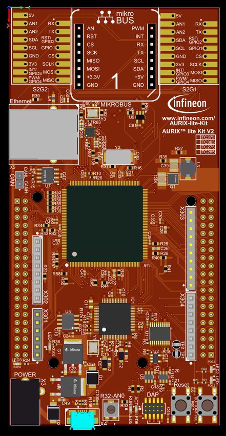
Copyright © Infineon Technologies AG 2021. All rights reserved.Hardware setup
This code example has been developed
for the board KIT_A2G_TC375_LITE.
In this example, the pin AN0, connected
to the board’s potentiometer, is used.
Note: The channels can be HW filtered by the
board, depending on which capacitor/resistors
couples are soldered. Consult the AURIX™
TC375 lite Kit’s User Manual to check which
channels are filtered by HW.
Note: The reference voltage (VAREF) of the
EVADC on the board KIT_A2G_TC375_LITE
is 3.3 V.
Copyright © Infineon Technologies AG 2021. All rights reserved.Implementation
Configuration of the EVADC
The configuration of the EVADC is done in the initEVADC() function in four different steps:
› Configuration of the EVADC module
› Configuration of the EVADC group
› Configuration of the EVADC channels
› Filling the queue
Configuration of the EVADC module with the function initEVADCModule()
The default configuration of the EVADC module, given by the iLLDs, can be used for this example.
This is done by initializing an instance of the IfxEvadc_Adc_Config structure and applying default values to
its fields through the function IfxEvadc_Adc_initModuleConfig().
Then, the configuration can be applied to the EVADC module with the function IfxEvadc_Adc_initModule().
Copyright © Infineon Technologies AG 2021. All rights reserved.Implementation
Configuration of the EVADC group with the function initEVADCGroup()
The configuration of the EVADC group is done by initializing an instance of the IfxEvadc_Adc_GroupConfig
structure with default values through the function IfxEvadc_Adc_initGroupConfig() and modifying the
following fields:
› groupId – to select which converters to configure
› master – to indicate which converter is the master. In this example, only one converter is used, therefore it
is also the master
› arbiter – a structure that represents the enabled request sources. In this example, it is set to
arbiter.requestSlotQueue0Enabled.
Then, the user configuration is applied through the function IfxEvadc_Adc_initGroup().
Copyright © Infineon Technologies AG 2021. All rights reserved.Implementation
Configuration of the EVADC channels with the function initEVADCChannels()
The configuration of each channel is done by initializing a separate instance of the
IfxEvadc_Adc_ChannelConfig structure with default values through the function
IfxEvadc_Adc_initChannelConfig() and modifying the following fields:
› channelId – to select the channel to configure
› resultRegister – to indicate the register where the A/D conversion value is stored
Then, the configuration is applied to the channel with the function IfxEvadc_Adc_initChannel().
Filling the queue
Each channel is added to the queue through the function IfxEvadc_Adc_addToQueue().
When the EVADC configuration is done and the queue is filled, the conversion is started with the function
IfxEvadc_Adc_startQueue().
Finally, to read a conversion, the function IfxEvadc_Adc_getResult() from iLLDs is used inside the function
readEVADC().
All the functions used for configuring the EVADC module, its groups and channels together with reading the
conversion results can be found in the iLLD header IfxEvadc_Adc.h.
Copyright © Infineon Technologies AG 2021. All rights reserved.Implementation
The visualization with LEDs is done using the functions initializeLEDs(), readEVADC() and
indicateConversionValue().
› The function initializeLEDs()
– initializes the port pins 13.0, 13.1 and 13.2 as push-pull outputs using the function
IfxPort_setPinMode()
– set the port pins 13.0, 13.1 and 13.2 to high state in order to switch the LEDs off by calling the function
IfxPort_setPinHigh()
› The function readEVADC()
– defines an object conversionResult of the type Ifx_EVADC_G_RES
– uses the function IfxEvadc_Adc_getResult() to continuously retrieve the result value until the valid
flag of the object conversionResult turns to high signaling that a new measurement is available
– assigns the converted value to the global variable g_result
› The function indicateConversionValue() is continuously executed and depending on the value of
g_result
– lights up the LED1 (P00.5) if the discrete converted value is greater than 0xAAA
– lights up the LED2 (P00.6) if the discrete converted value is smaller than 0x555
– lights up the LED1 (P00.5) and LED2 (P00.6) if the discrete converted value is smaller or equal to
0xAAA and greater or equal to 0x555
Copyright © Infineon Technologies AG 2021. All rights reserved.Run and Test
After code compilation and flashing the device, verify the behavior of the LEDs:
› Turn the potentiometer on the board
and observe LED1 and LED2.
1 2
Input Voltage X LED1 LED2
X < 1.1 V
1.1 VReferences
› AURIX™ Development Studio is available online:
› https://www.infineon.com/aurixdevelopmentstudio
› Use the „Import...“ function to get access to more code examples.
› More code examples can be found on the GIT repository:
› https://github.com/Infineon/AURIX_code_examples
› For additional trainings, visit our webpage:
› https://www.infineon.com/aurix-expert-training
› For questions and support, use the AURIX™ Forum:
› https://www.infineonforums.com/forums/13-Aurix-Forum
Copyright © Infineon Technologies AG 2021. All rights reserved.Trademarks
All referenced product or service names and trademarks are the property of their respective owners.
Edition 2021-03 IMPORTANT NOTICE For further information on the product,
Published by The information given in this document shall in no technology, delivery terms and conditions and
Infineon Technologies AG event be regarded as a guarantee of conditions or prices please contact your nearest Infineon
81726 Munich, Germany characteristics (“Beschaffenheitsgarantie”) . Technologies office (www.infineon.com).
With respect to any examples, hints or any typical
© 2021 Infineon Technologies AG. WARNINGS
values stated herein and/or any information
All Rights Reserved. Due to technical requirements products may
regarding the application of the product, Infineon
contain dangerous substances. For information
Technologies hereby disclaims any and all
Do you have a question about this on the types in question please contact your
warranties and liabilities of any kind, including
document? nearest Infineon Technologies office.
without limitation warranties of non-infringement
Email: erratum@infineon.com
of intellectual property rights of any third party. Except as otherwise explicitly approved by
Infineon Technologies in a written document
Document reference In addition, any information given in this
signed by authorized representatives of Infineon
ADC_Single_Channel_1_ document is subject to customer’s compliance
Technologies, Infineon Technologies’ products
KIT_TC375_LK with its obligations stated in this document and
may not be used in any applications where a
any applicable legal requirements, norms and
failure of the product or any consequences of the
standards concerning customer’s products and
use thereof can reasonably be expected to result
any use of the product of Infineon Technologies in
in personal injury.
customer’s applications.
The data contained in this document is exclusively
intended for technically trained staff. It is the
responsibility of customer’s technical
departments to evaluate the suitability of the
product for the intended application and the
completeness of the product information given in
this document with respect to such application.You can also read