ASCLIN_Shell_UART_1 for KIT_AURIX_TC377_TFT - Shell via UART communication AURIX TC3xx Microcontroller Training - Infineon Technologies
←
→
Page content transcription
If your browser does not render page correctly, please read the page content below
ASCLIN_Shell_UART_1
for KIT_AURIX_TC377_TFT
Shell via UART communication

AURIX™ TC3xx Microcontroller Training
V1.0.1
                Please read the Important Notice and Warnings at the end of this document
Scope of work
A Shell is used to parse a command line and call the corresponding
command execution. The ASCLIN module is used to interface with the
Shell through the USB port via UART.
The ASCLIN module is configured for UART communication.
The Shell from iLLDs exploits the ASCLIN module to interpret and manage
commands from the user like “info”, “toggle [x]” or “help”.
Copyright © Infineon Technologies AG 2021. All rights reserved.Introduction
› The Asynchronous/Synchronous Interface (ASCLIN) module provides
serial communication with external devices. In this example, it is used to
interface with the PC through the USB port via UART communication
› A Shell is a user interface for parsing commands and accessing services
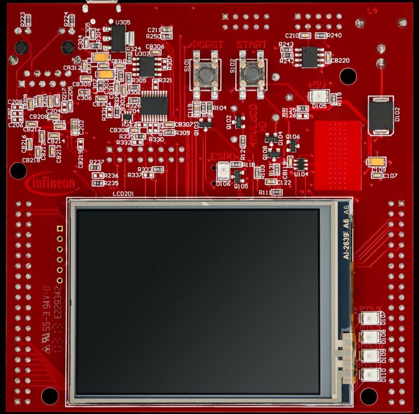
Copyright © Infineon Technologies AG 2021. All rights reserved.Hardware setup
This code example has been 1
developed for the board
KIT_A2G_TC377_5V_TFT.
The board should be connected to
the PC through the USB port (1).
Copyright © Infineon Technologies AG 2021. All rights reserved.Implementation
Configure the ASCLIN module
The configuration of the ASCLIN module is done by initializing an instance of the IfxAsclin_Asc_Config
structure, which contains the following fields:
› baudrate – a structure that allows to set
– baudrate – the communication speed in bit/s
– oversampling – the division ratio of the baud rate for reaching higher frequencies to ensure
oversampling
› bitTiming – a structure that allows to set the sampling mode with
– medianFilter – the number of samples per bit
– samplePointPosition – the first sample point position
› interrupt – a structure that allows to set
– txPriority, rxPriority and erPriority – the interrupt priorities for transmission, reception and error
events
– typeOfService – the service provider responsible for handling the interrupt, which can be any of the
available CPUs, or the DMA
› pins – a structure that allows to set which port pins are used for the communication
› rxBuffer, rxBufferSize, txBuffer, txBufferSize – parameters that allow to configure the buffers that will
hold the incoming/outgoing data
The function IfxAsclin_Asc_initModuleConfig() fills the configuration structure with default values and
IfxAsclin_Asc_initModule() function initializes the module with the user configuration.
Both the functions can be found in the iLLD header IfxAsclin_Asc.h.
Copyright © Infineon Technologies AG 2021. All rights reserved.Implementation
Configure the Shell
To configure the Shell, it is needed to firstly initialize a Standard Interface and a console from the iLLDs.
This is done by the functions IfxAsclin_Asc_stdIfDPipeInit() and Ifx_Console_init(), that can be found
respectively in the iLLDs headers IfxAsclin_Asc.h and Ifx_Console.h.
The Shell is configured inside the function initShellInterface() by initializing an instance of the
Ifx_Shell_Config structure with default values through the function Ifx_Shell_initConfig(). Then, the
following parameters are modified:
› standardIo – that allows to set the module used for serial communication
› commandList – that allows to set the list of commands supported by the shell
The command list is an array of structures of the type Ifx_Shell_Command, that contains:
– commandLine – the actual command which will be sent to the shell by the user
– help – a small description of the command that is shown when help command is given
– data – a link to the shell
– call – the function called when the command is given
The Ifx_Shell_init() function initializes the shell with the user configuration.
The functions Ifx_Shell_initConfig() and Ifx_Shell_init() can be found in the iLLD header Ifx_Shell.h, while
the function initShellInterface() is defined in the header ASCLIN_Shell_UART.h.
Copyright © Infineon Technologies AG 2021. All rights reserved.Implementation
Run the Shell
The Shell is continuously run through the function runShellInterface() called inside the infinite while loop in
the Cpu0_Main.c file.
It continuously reads the incoming data and evaluates it when the carriage return character is entered.
Configure and control the LEDs
The LEDs are toggled by controlling the port pins to which they are connected using methods from the iLLD
headers IfxPort.h.
The LED port pins have to be configured to output push-pull mode using the function
IfxPort_setPinMode().
During program execution, the LEDs are switched on and off using the function IfxPort_setPinState().
Copyright © Infineon Technologies AG 2021. All rights reserved.Implementation
Configure the Interrupt Service Routine (ISR)
The function implementing the ISR needs to be assigned a priority via the macro
IFX_INTERRUPT(isr, vectabNum, priority).
Since the Shell uses the ASCLIN module to interface with the user, three ISRs are needed to be configured
for transmission, reception and error events.
Each ISR should call the handler for the respective operation (transmit, receive or error) by passing the ASC
handle.
Copyright © Infineon Technologies AG 2021. All rights reserved.Run and Test
› For this training, a serial monitor is required for using the Shell. The monitor can be opened
inside the AURIX™ Development Studio using the following icon:
› The serial monitor must be configured with
the following parameters to enable the
communication between the board and the
PC:
– Speed (baud): 115200
– Data bits: 8
– Stop bit: 1
Copyright © Infineon Technologies AG 2021. All rights reserved.Run and Test
Firstly, the serial monitor should be opened. After code compilation and
flashing the device, perform the following steps:
› Type “help” to see the list of available commands
› Type “toggle [0/1/2/3/4]” to respectively: turn on all LEDs, toggle LED
D107, toggle LED D108, toggle LED D109 or toggle LED D110
› Check command execution
Copyright © Infineon Technologies AG 2021. All rights reserved.References
› AURIX™ Development Studio is available online:
› https://www.infineon.com/aurixdevelopmentstudio
› Use the „Import...“ function to get access to more code examples.
› More code examples can be found on the GIT repository:
› https://github.com/Infineon/AURIX_code_examples
› For additional trainings, visit our webpage:
› https://www.infineon.com/aurix-expert-training
› For questions and support, use the AURIX™ Forum:
› https://www.infineonforums.com/forums/13-Aurix-Forum
Copyright © Infineon Technologies AG 2021. All rights reserved.Revision history
Revision Description of change
V1.0.1 Removed assert initialization not needed for the scope of the training
V1.0.0 Initial version
Copyright © Infineon Technologies AG 2021. All rights reserved.Trademarks
All referenced product or service names and trademarks are the property of their respective owners.
Edition 2021-03 IMPORTANT NOTICE For further information on the product,
Published by The information given in this document shall in no technology, delivery terms and conditions and
Infineon Technologies AG event be regarded as a guarantee of conditions or prices please contact your nearest Infineon
81726 Munich, Germany characteristics (“Beschaffenheitsgarantie”) . Technologies office (www.infineon.com).
With respect to any examples, hints or any typical
© 2021 Infineon Technologies AG. WARNINGS
values stated herein and/or any information
All Rights Reserved. Due to technical requirements products may
regarding the application of the product, Infineon
contain dangerous substances. For information
Technologies hereby disclaims any and all
Do you have a question about this on the types in question please contact your
warranties and liabilities of any kind, including
document? nearest Infineon Technologies office.
without limitation warranties of non-infringement
Email: erratum@infineon.com
of intellectual property rights of any third party. Except as otherwise explicitly approved by
Infineon Technologies in a written document
Document reference In addition, any information given in this
signed by authorized representatives of Infineon
ASCLIN_Shell_UART_1_ document is subject to customer’s compliance
Technologies, Infineon Technologies’ products
KIT_TC377_TFT with its obligations stated in this document and
may not be used in any applications where a
any applicable legal requirements, norms and
failure of the product or any consequences of the
standards concerning customer’s products and
use thereof can reasonably be expected to result
any use of the product of Infineon Technologies in
in personal injury.
customer’s applications.
The data contained in this document is exclusively
intended for technically trained staff. It is the
responsibility of customer’s technical
departments to evaluate the suitability of the
product for the intended application and the
completeness of the product information given in
this document with respect to such application.You can also read