Razor: An Architecture for Dynamic Multiresolution Ray Tracing
←
→
Page content transcription
If your browser does not render page correctly, please read the page content below
Razor: An Architecture for Dynamic Multiresolution Ray Tracing
PETER DJEU
University of Texas at Austin
WARREN HUNT
Intel Labs
RUI WANG
University of Massachusetts Amherst
IKRIMA ELHASSAN
Microsoft Corporation
GORDON STOLL
Intel Labs
and
WILLIAM R. MARK
Intel Labs

Recent work demonstrates that interactive ray tracing is possible on desktop       using a two-phase shading scheme inspired by the REYES system, and
systems, but there is still much debate as to how to most efficiently support      caches tessellated representations of freeform surfaces at multiple levels of
advanced visual effects such as soft shadows, smooth freeform surfaces,            detail.
complex shading, and animated scenes. With these challenges in mind, we               We present experimental results gathered from a prototype system im-
reconsider the options for designing a rendering system and present Razor,         plemented on eight CPU cores, and discuss which aspects of the system are
a new software rendering architecture for distribution ray tracing designed        most successful and which would benefit from further investigation.
to produce high-quality images with high performance on future single-
                                                                                   Categories and Subject Descriptors: I.3.7 [Computer Graphics]: Three-
chip many-core hardware. Razor includes two noteworthy capabilities: a
                                                                                   Dimensional Graphics and Realism—Raytracing; I.3.3 [Computer Graph-
set of techniques for quickly building the kd-tree acceleration structure on
                                                                                   ics]: Picture/Image Generation—Display algorithms
demand every frame from a scene graph and a system design that allows
for crack-free multiresolution geometry with each ray independently choos-         General Terms: Algorithms, Design, Performance
ing its geometry resolution. Razor’s per-frame kd-tree build is designed to
                                                                                   Additional Key Words and Phrases: Distribution ray tracing, real-time ray
robustly handle arbitrarily scene animation, while its per-ray multiresolu-
                                                                                   tracing, hierarchical build, lazy build, parallel build, level of detail, mul-
tion geometry provides continuous level of detail driven by ray and path
                                                                                   tiresolution, subdivision surfaces
differentials. Razor also decouples shading from visibility computations
                                                                                   ACM Reference Format:
                                                                                   Djeu, P., Hunt, W., Wang, R., Elhassan, I., Stoll, G., and Mark, W. R. 2011.                      115
W. Hunt, I. Elhassan, and W. R. Mark were at the University of Texas at            Razor: An architecture for dynamic multiresolution ray tracing. ACM Trans.
Austin during the period that most of this work was conducted.                     Graph. 30, 5, Article 115 (October 2011), 26 pages.
This research was funded by Intel Corporation and NSF CAREER award                 DOI = 10.1145/2019627.2019634
no. 0546236.                                                                       http://doi.acm.org/10.1145/2019627.2019634
Authors’ addresses: P. Djeu, Department of Computer Science, University
of Texas at Austin, Austin, TX; W. Hunt, Intel Labs; R. Wang, Depart-
ment of Computer Science, University of Massachusetts Amherst, Amherst,            1.   INTRODUCTION
MA; I. Elhassan, Microsoft Corporation; G. Stoll, Intel Labs; W. R. Mark
(corresponding author), Intel Labs; email: billmark@billmark.com.                  It has been a longstanding goal in computer graphics to interactively
Permission to make digital or hard copies of part or all of this work for          synthesize realistic images, and to provide artists with powerful
personal or classroom use is granted without fee provided that copies are          creative control over image generation. Despite much progress over
not made or distributed for profit or commercial advantage and that copies         the past thirty years current interactive graphics systems are still far
show this notice on the first page or initial screen of a display along with       from these goals.
the full citation. Copyrights for components of this work owned by others             It is becoming increasingly clear that there are significant limita-
than ACM must be honored. Abstracting with credit is permitted. To copy            tions with the Z-buffer algorithm used in today’s interactive graphics
otherwise, to republish, to post on servers, to redistribute to lists, or to use   systems. Within the next 5 years, we believe that the Z-buffer algo-
any component of this work in other works requires prior specific permission       rithm will begin to be augmented or replaced with algorithms such
and/or a fee. Permissions may be requested from Publications Dept., ACM,           as ray tracing [Whitted 1980] that efficiently support a more general
Inc., 2 Penn Plaza, Suite 701, New York, NY 10121-0701 USA, fax +1                 class of visibility queries. This transition to ray tracing is already
(212) 869-0481, or permissions@acm.org.                                            well under way in offline rendering [Tabellion and Lamorlette 2004;
!c 2011 ACM 0730-0301/2011/10-ART115 $10.00                                        Christensen et al. 2006].
DOI 10.1145/2019627.2019634                                                           Ray tracing has made significant advances in the interactive do-
http://doi.acm.org/10.1145/2019627.2019634                                         main already. Recently developed interactive ray tracing systems
                                                                                        ACM Transactions on Graphics, Vol. 30, No. 5, Article 115, Publication date: October 2011.
115:2 • P. Djeu et al.
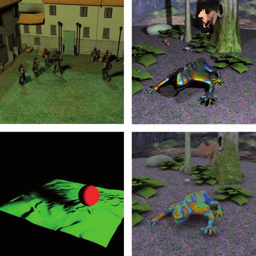
Fig. 1. Images rendered by Razor at near-interactive frame rates. From the left, the first three scenes have millions of visible micropolygons while the last
scene is a technical demo. All four scenes are rendered at 1024 × 1024 resolution with a total of 36 rays per pixel (4× supersampling, 2 area lights, and
4 shadows rays/primary ray/light). The two scenes on the left use piecewise bilinear patches while the two scenes on the right consist entirely of subdivision
surfaces. The render times are 3.83 sec, 3.77 sec, 6.94 sec, and 3.36 sec using eight Xeon X5355 cores. The models used these images appear courtesy of their
respective owners.1
[Parker et al. 1999, 2010; Woop et al. 2005, 2006; Reshetov et al. dynamic motion; efficient support for automatic multiresolution
2005; Wächter and Keller 2006; Lauterbach et al. 2006; Bigler geometry; and an overall system architecture that ties everything
et al. 2006; Wald et al. 2007a; Bikker 2007; Caustic Graphics 2009] together along with existing ideas for decoupling shading compu-
demonstrate that interactive ray tracing is starting to become a viable tations from visibility hit points. Our approach is forward looking,
technique. Yet these existing systems typically have serious limita- meaning that Razor is explicitly designed to support a rich set of
tions that make them impractical or insufficient for most mainstream functionality for future interactive use on future hardware. This
interactive applications. Many of these systems perform poorly for strategy contrasts with most other recent work on interactive ray
large dynamic scenes, and some of them only implement classical tracing, which takes the opposite approach of restricting functional-
Whitted ray tracing, which for many applications does not provide ity (e.g., dynamics) or image quality (e.g., resolution, visual effects,
a compelling improvement in visual quality over state-of-the-art shading) so that the system can run at interactive rates on today’s
Z-buffer rendering. hardware. We present results gathered from an experimental imple-
The true advantages of ray tracing visibility algorithms only be- mentation of our design on 2006-era hardware (see Figure 1). As
come apparent with the addition of effects that are typically pro- expected, the frame rates achieved on this hardware are not inter-
duced using distribution ray tracing [Cook et al. 1984] and/or other active except at very low image quality and resolution settings. We
advanced techniques. These effects include soft shadows, glossy re- discuss what we have learned about the strengths and weaknesses
flections, diffuse reflections, ambient occlusion, subsurface scatter- of various aspects of our design.
ing, final gathering from photon maps, and others. But most current It is important to understand that Razor is an experimental system
distribution ray tracing systems have several sources of inefficiency. with a complex new design. Not surprisingly, some aspects of the
They have high overhead to support dynamic scenes, use excessively design have been more successful than others, and taken as a whole
detailed geometry for secondary rays, perform redundant computa- we consider the system to be only partially successful in meeting
tions for shading and secondary rays, and have irregular data access its design goals. The findings section near the end of the article
and computation patterns that are a poor match for cost-effective attempts to objectively discuss the strengths and weaknesses of the
hardware. Successfully addressing these inefficiencies would make design, with the hope that future efforts can benefit from the lessons
ray tracing a more attractive alternative to Z-buffer rendering for that we have learned.
interactive applications. This article is a revised and extended version of two earlier tech-
In this article, we discuss some of the inefficiencies in conven- nical reports about Razor [Stoll et al. 2006; Djeu et al. 2007], and is
tional distribution ray tracing systems, and propose a new rendering intended to be the archival reference for the Razor system design.
system architecture that attempts to reduce or eliminate several of The high-level design of Razor was completed in 2005 with some
these inefficiencies. We focus our innovation on the visibility engine adjustments made in 2006. The vast majority of the implemention
and on the interactions between the visiblity engine and the local and evaluation work was completed by January 2007. We have
shading engine. We do not attempt to innovate in the area of light written three other articles related to Razor. Two articles discuss
transport and global illumination algorithms, where we rely on es- our techniques for rapidly building a kd-tree acceleration structure
tablished distribution ray tracing techniques. More specifically, we [Hunt et al. 2006, 2007], but in the context of a single resolution
focus our innovation in three areas: efficient support for arbitrary kd-tree rather than the multiresolution kd-tree described here. A
third article, published in a computer architecture conference, an-
1 The character models in Courtyard64 (first scene) are copyright Digital
alyzes Razor’s performance on a simulated single-chip many-core
Extremes, all rights reserved. The character models in Courtyard64 use mo-
computer architecture [Govindaraju et al. 2008].
tion capture data from mocap.cs.cmu.edu (NSF EIA-0196217). The dragon
model in Forest (third scene) appears courtesy of Jeffery A. Williams and 1.1 Key Techniques
Intel Corporation. The killeroo model in Forest appears courtesy of Phil
Dench, Martin Rezard, and headus (metamorphosis) Pty Ltd. The floor in The most important techniques used by Razor are the following.
Forest appears courtesy of Jonathan Dale. The background models in Forest Per-frame dynamic and lazy kd-tree build. Razor incorporates an
appear courtesy of DAZ Productions. algorithm for lazily building a multiresolution kd-tree each frame
ACM Transactions on Graphics, Vol. 30, No. 5, Article 115, Publication date: October 2011.
Razor: An Architecture for Dynamic Multiresolution Ray Tracing                               •      115:3

from a tightly integrated hierarchial scene graph representing a               —Efficiently support all forms of geometry motion. Modern Z-buffer
dynamic scene. All major system data structures except the original             rendering systems efficiently support moving, deforming, and
scene graph are rebuilt every frame. The hierarchial scene graph                changing geometry even in large scenes with high depth com-
can be thought of as a coarse, poor-quality spatial data structure              plexity; it is important that a ray tracer do the same.
that is incrementally updated and thus benefits from frame-to-frame            —Support curved surfaces and detailed geometry. Most future real-
coherence. This coarse information is sufficient to allow the high-             time rendering systems (including Z-buffer ones) are likely to be
quality kd-tree acceleration structure to be inexpensively rebuilt on           required to support high-quality geometric detail using mecha-
demand each frame. (This article extends the authors’ previously                nisms such as subdivision surfaces and displacement mapping.
published techniques [Hunt et al. 2006; Hunt et al. 2007] to support           —Efficient real-time performance on future single-chip many-core
multiresolution geometry in a micropolygon system.)                             architectures. The system should be suitable for use by real-
   Ray-directed continuous multiresolution geometry. Razor per-                 time applications such as games on future single-chip many-core
forms ray tracing on continuous, crack-free level of detail surfaces,           graphics hardware. In particular, we target architectures with a
while avoiding popping and tunneling artifacts even for camera rays.            flexible programming model supporting task parallelism across
Each ray independently selects a geometric level of detail, which               multiple cores and data parallelism with SIMD instructions on
varies along the ray based on ray and path differentials. We refer to           each core.
this capability as ray-directed level of detail. The continuous levels
of detail are synthesized by interpolating on-the-fly between discrete         Just as importantly, we defined nongoals for Razor.
levels of detail stored in the acceleration structure. These discrete
                                                                               —No backward compatibility. We reconsider the entire system
levels of detail are generated on demand by adaptive subdivision
                                                                                structure, including the format of the input scenes. We allow
of input meshes. (These ideas are the primary novel algorithmic
                                                                                Razor to break compatibility with old APIs and to require that
contribution of this article.)
                                                                                scenes be modeled and presented to the system in new ways.
   Partially decoupled shading and visibility. By splitting shading
computations into two phases, Razor allows visibility to be com-               —No barrier between application and renderer. Traditional Z-
puted at a higher spatial frequency than most shading computations.             buffer APIs such as OpenGL and DirectX strictly decouple ap-
(This approach combines several previous ideas, and in particular               plication data structures such as a scene graph from the rendering
can be thought of as an extension of the grid-based shading approach            system. We allow Razor to couple these data structures to each
pioneered in the REYES system [Cook et al. 1987] to a 100% ray                  other.
tracing framework.)                                                            —No requirement for real-time performance on todays’s hardware.
   Partially replicated kd-trees supporting parallel construction.              Razor is targeted at future hardware with higher performance
Razor builds multiple partially complete kd-trees in parallel, by               for ray tracing than today’s CPUs or GPUs. In contrast, the de-
leveraging the laziness of tree construction. This strategy allows ac-          signers of most other systems targeted at interactive rendering
celeration structure build to be parallelized without overhead from             have imposed an artificial requirement that the systems run at
communication or mutual exclusion, and allows on-demand con-                    interactive rates on today’s hardware, even though it is clear that
struction to be performed at a fine granularity with reasonable effi-           future hardware with a somewhat different architecture (e.g., that
ciency. (This technique is a relatively straightforward extension of            of Seiler et al. [2008]) could provide higher performance than
lazy build to parallelism).                                                     today’s CPUs and more flexibility than today’s GPUs.
   A new system architecture. Razor combines the techniques just               —Not as flexible as a batch renderer. Batch rendering systems are
mentioned into a prototype system that achieves near-interactive                expected to be extremely flexible with support for a wide variety
frame rates on dynamic models whose triangle count is similar to                of rendering options. In contrast, it is acceptable for systems
that of modern game scenes. (This novel combination of techniques               targeted for interactive use to be less flexible in order to improve
and their evaluation represents the “rendering systems” contribution            performance. This pattern is shown very clearly by today’s real-
of this article).                                                               time Z-buffer-based systems.
1.2   Organization of Article                                                  —Not a product-quality system. Razor is an experimental system,
                                                                                and it does not strive for the same level of feature complete-
The remainder of the article is organized as follows: First, we pro-            ness and robustness that would be required for a product-quality
vide an overview of Razor’s goals and design at a high level. Sec-              system. Razor innovates on a large number of dimensions, and
ond, we describe Razor’s design in detail, focusing on the more                 as such we accept that some aspects of its design may be less
technically novel aspects of the design. Third, we evaluate various             successful than others.
aspects of Razor’s design using quantitative results obtained from
our prototype implementation. Fourth, we discuss previous work,                3.     THE CHALLENGES
and how various elements of Razor are related to that work. Finally,
we describe what we learned from Razor: which ideas worked well,               Given the goals just mentioned, several challenges are apparent.
which didn’t, and which would benefit from further investigation.                 Overall system performance. Distribution ray tracing is compu-
The article is long: It combines a new overall rendering system                tationally expensive, so performance must be a key consideration
design with several specific technical innovations needed to make              in every design decision.
that design viable.                                                               Dynamic scenes. If objects are moving within the scene, it is not
                                                                               possible to treat the construction of a spatial acceleration structure
2.    GOALS                                                                    as a “free” preprocessing step; part or all of the work must be
                                                                               performed each frame. Furthermore, if the objects undergo nonrigid
The design of Razor was driven by the following goals.                         motion such as deformation (as is common in skinned characters
—Support distribution ray tracing effects. These effects include               used in computer games), then it is not possible to use the common
  soft shadows, ambient occlusion, and depth of field in addition              optimization of prebuilding acceleration structures for individual
  to traditional Whitted-style effects such as specular reflection.            objects.
                                                                         ACM Transactions on Graphics, Vol. 30, No. 5, Article 115, Publication date: October 2011.
115:4        •       P. Djeu et al.

   If the scene is complex with many occlusions (such as an entire                           —For actual ray/surface intersection tests, use triangles. Experi-
building with occupants), then building or updating the entire ac-                            ence with Z-buffer systems, interactive ray tracing systems, and
celeration structure every frame is too costly, even with a fast build                        many offline ray tracing systems (e.g., that of Christensen et al.
technique. This problem is even more acute if we want to represent                            [2003]) has shown that it is wise to use a single simple geometric
each object at multiple levels of detail: the time and memory re-                             primitive (specifically a triangle or quad) for final intersection
quirments for creating and storing tessellated geometry at the finest                         testing, even if this choice necessitates an earlier tessellation step
level of detail for the entire scene are prohibitive.                                         (as is the case in Razor). Razor uses triangles, and this choice
   Efficiency of distribution-sampled secondary rays. Distribution                            allows the system’s inner loops and corresponding data structures
ray tracing systems cast large numbers of secondary rays. For ex-                             to be highly specialized and performance tuned for ray/triangle
ample, many rays are cast to sample area light sources and for                                intersection testing and acceleration structure construction. As
ambient occlusion computations. There are many more secondary                                 we will discuss in Section 5.1.3, these triangles are generated by
rays than primary rays, so the cost of tracing the secondary rays and                         adaptively tessellating subdivision surfaces.
tessellating the geometry they hit dominates the ray tracing time.                           —Use a cost-optimized acceleration structure (specifically a kd-
   Worse yet, the traversal of the acceleration structure by                                  tree). Previous experience shows that achiving good traversal
distribution-sampled secondary rays is less coherent than that of                             performance for rays requires the use of a highly efficient accel-
primary rays [Christensen et al. 2003; Navrátil and Mark 2006;                               eration structure. In particular, the partitions in the acceleration
Mansson et al. 2007], which increases the per-ray cost. In particular,                        structure must be chosen so as to minimize expected traversal
when tracing distribution-sampled secondary rays using a standard                             cost as predicted by the surface area heuristic [Goldsmith and
acceleration structure, techniques for exploiting SIMD hardware are                           Salmon 1987]. Razor uses a cost-optimized kd-tree [Havran and
less effective, and the ray tracer accesses a large memory working                            Bittner 2002] as its primary acceleration structure, along with
set for which caches are less effective than for primary rays.                                modifications described in Section 5.2 to support multiresolution
   Redundant shading computations. Most ray tracers perform shad-                             capabilities. For scenes that are animated, this decision raises the
ing computations at each ray hit point. At high screen-space super-                           question of whether it is possible to efficiently construct or up-
sampling rates, most of these shading computations are redundant.                             date a cost-optimized kd-tree, and we will address this question
The situation is even worse for shaders that require arbitrary dif-                           in Section 5.2.2. We note that prior to this work, most interactive
ferential computations, since these shaders must either be run three                          ray tracing systems supporting arbitrary dynamic scenes avoided
times at each hit point to compute discrete differentials [Gritz and                          the use of cost-optimized acceleration structures, because it was
Hahn 1996], or perform the extra computations needed for auto-                                believed that they were too expensive to construct.
matic differentiation using dual number arithmetic [Piponi 2004;
Karrenberg et al. 2010; Gritz et al. 2010]. Redundant shading com-                           —Use ray packets for efficiency on SIMD hardware. One of the
putations can severely degrade overall system performance, since it                           best ways for hardware to provide high computational through-
is common for a renderer’s surface shading costs to be a substantial                          put at minimal cost is use register SIMD instructions, such as
part of the total rendering cost.                                                             SSE. Modern GPUs use 16-wide, 32-wide, or 48-wide SIMD
                                                                                              hardware, although in some cases the SIMD hardware is hidden
                                                                                              behind a nominally scalar ISA [Lindholm et al. 2008]. SIMD
                                                                                              hardware amortizes the overheads of instruction fetch, decode,
4.    DESIGN DECISIONS                                                                        and branching; and improves the coherence of accesses to cache
In this section, we describe the key decisions made in the Razor                              and to DRAM. Previous work has shown that ray tracers can
design. First, we describe several elements of the design that are                            make efficient use of SIMD hardware by aggregating rays into
relatively conventional. Second, we describe design choices that are                          packets [Wald et al. 2001]. Packets are extremely efficient when
more unusual and represent the most important differences between                             rays are spatially coherent (e.g., camera rays or hard shadow
Razor and other rendering systems. Third, we describe additional                              rays), but become less efficient as rays lose their coherency. One
design choices that help to support the novel design choices.                                 of the major goals of Razor’s design was to maximize the effi-
                                                                                              ciency of packet techniques for semicoherent rays such as soft
                                                                                              shadow rays. (Concurrent work by others has also shown that
4.1     Conventional Decisions                                                                that packets are useful for distribution ray tracing [Boulos et al.
                                                                                              2007]). In its default configuration, Razor uses 32-wide packets,
Several of the design decisions in Razor are fairly conventional, but
                                                                                              implemented as eight 4-wide SSE operations. Even on 4-wide
need to be explicitly mentioned to understand the remainder of the
                                                                                              hardware, the 32-wide packets help performance by amortizing
system.
                                                                                              branch overhead, but this design will be even more efficient on
   The first few of these decisions are so standard that we do not
                                                                                              future, wider SIMD hardware.
attempt to explcitly justify them; it is perhaps more proper to con-
sider them as additional goals or constraints for the system design.
We choose to represent the scene using an explicit boundary repre-                           4.2    Unusual Decisions
sentation (rather than, e.g., a volumetric representation); we choose                        There are three key design decisions for Razor that taken together
to use discrete rays as the only visibility primitives (rather than,                         make it substantially different from other ray tracing systems, and in
e.g., beams [Heckbert and Hanrahan 1984]); and we choose to use                              particular make it different from other systems targeted at interactive
a variant of distribution ray tracing [Cook et al. 1984] to sample                           use. We will describe these decisions, and explain why they were
various visibility integrals.                                                                made.
   In addition, Razor’s goal of achieving high efficiency led to sev-
eral relatively conventional design choices based on experience                              —Use multiresolution surfaces and a robust multiresolution accel-
with earlier high-performance rendering systems. These bottom-up                              eration structure. In the past few years, batch rendering systems
performance-driven choices have the effect of constraining and/or                             [Christensen et al. 2003; Tabellion and Lamorlette 2004] have
inspiring other aspects of the system design.                                                 demonstrated that most secondary rays can be traced using coarse
ACM Transactions on Graphics, Vol. 30, No. 5, Article 115, Publication date: October 2011.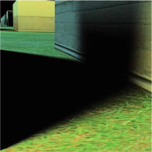
Razor: An Architecture for Dynamic Multiresolution Ray Tracing                               •      115:5

  geometric representations of the scene, without harming image                    dramatically increase the size of the acceleration structure. Third,
  quality. Mathematically this situation is explained by the fact that             this decision supports the goal of efficiency, since acceleration
  most secondary rays have large ray differentials [Igehy 1999], that              structures that are rebuilt often perform better than those that are
  is, they diverge strongly from each other as they progress away                  incrementally updated (especially if topology cannot be updated).
  from their origins. Furthermore, errors in secondary visibility                  Razor uses as its acceleration structure a kd-tree optimized ac-
  are typically much less perceptually objectionable than errors in                cording to the surface area heuristic. Razor uses several novel
  primary visibility.                                                              techniques that permit rapid construction of this high-quality ac-
     The advantage of using a coarse geometric representation for                  celeration structure.
  secondary rays is that it can improve the coherence of secondary                    Razor builds its acceleration structure on demand throughout
  ray traversal, which in turn improves overall system performance.                the rendering of the frame, rather than at the start of the frame.
  In particular, a coarse geometry representation reduces the mem-                 This approach avoids wasted work for portions of the scene that
  ory working set required by secondary rays so that cache hit                     are not visible, and ensures that information is available about
  rates are higher, and improves the effectiveness of ray packet                   which resolution(s) of geometry are needed. When a ray enters
  techniques needed to achieve high efficiency on SIMD hardware.                   a previously unbuilt node of the acceleration structure, that node
     For this reason, Razor uses a multiresolution representation                  is built at the needed resolution, and traversal is resumed. An
  of geometry that allows secondary rays to access an appropriate                  application-maintained scene graph provides the coarse scene
  (typically coarse) geometric representation, as determined by ray                organization required to identify scene geometry to be inserted
  differentials. The geometry resolution used by secondary rays is                 into the acceleration structure. This scene graph also provides a
  not constrained by the resolution used by primary rays as it is in               coarse spatial sort that reduces the cost of building a high-quality
  some other systems [Christensen et al. 2006]. Most importantly,                  acceleration structure, as compared to approaches that build from
  there is no longer a single reference point (the camera point) with              a “triangle soup.” This design requires a close coupling between
  which to set the resolution of each surface in the scene. Instead,               the rendering engine and the application scene graph.
  each ray (including secondary rays) may request a geometric res-                    The decision to rebuild the acceleration structure on demand
  olution that is essentially unrelated to that requested by any other             every frame from potentially changing geometry places con-
  ray. We refer to this capability as ray-directed level of detail, in             straints on other aspects of the design. For example, the multires-
  contrast to the more traditional camera-directed level of detail.                olution representation cannot require extensive preprocessing of
  Because of the initial design decision that Razor would use ray                  geometry or rely on information about global topology.
  tracing for all rays (i.e., primary rays as well as all types of sec-
  ondary rays), the multiresolution representation and associated               —Decouple shading from visibility to reduce redundant shading
  intersection testing must be robust enough to avoid objectionable              computations. Most ray tracing rendering systems perform shad-
  artifacts for primary rays, while still allowing secondary rays to             ing computations at the ray hit points. However, this approach
  access a different resolution from primary rays without crack-                 is inefficient when there is an opportunity to perform shading
  ing artifacts. This problem had not been solved previously in a                computations at a lower sampling rate than visibility computa-
  multiresolution ray tracer, and led us to develop a novel multires-            tions, as is the case when casting many primary rays per pixel.
  olution acceleration structure, along with associated traversal and            The REYES system [Cook et al. 1987] and the multisampling in
  intersection algorithms. This acceleration structure conceptually              modern Z-buffer graphics systems [Akenine-Möller and Haines
  represents each region of space at all possible resolutions. In the            2002] avoid this problem by decoupling shading from visibil-
  actual algorithm, each region of space is represented at one or                ity. However, these previous systems are used only for primary
  more discrete resolutions. The associated traversal and intersec-              visibility (camera rays), where it can be assumed that all rays
  tion algorithms interpolate on-the-fly between the discrete res-               originate at a single point (the camera point). This assumption
  olutions, so that rays are intersected with geometry represented               does not hold in a ray tracer.
  at a continuously varying level of detail that is not subject to
                                                                                    Razor extends the idea of decoupling shading from visibil-
  popping or cracking artifacts.
                                                                                 ity to work for all types of rays in a ray tracing system. Ra-
     Details of this design and the considerations that led to it are            zor splits shading into two phases [Pharr and Humpreys 2004],
  discussed in Section 5.1.                                                      one which is view independent (typically, the computation of
—Support dynamic scenes and multiresolution geometry by build-                   the material properties), and another which is view dependent.
 ing the acceleration structure on demand each frame, using the                  The view-independent computation is decoupled from visibility
 application scene graph as input. Razor rebuilds the acceleration               by performing it on a regularly spaced grid of points in object
 structure every frame. More precisely, Razor builds only those                  space and interpolating the results at visibility hit points. This
 spatial regions and resolution(s) of the acceleration structure that            computation is performed on demand, after a grid has been hit
 are needed for the current frame. In contrast, many interactive                 by a ray. More specifically, as inspired by REYES, the system
 ray tracing systems choose to preserve the acceleration structure               tessellates geometry into micropolygons and performs the view-
 from frame to frame, making updates to node bounds to account                   independent shading computations at the polygon vertices. The
 for motion.                                                                     view-dependent computations are always performed at hit points,
    The decision to rebuild the acceleration structure each frame                as in a conventional ray tracer. This idea is conceptually simple,
 was made for three reasons: First, this decision supports the goal              but making it work correctly without artifacts in a multiresolution
 of allowing arbitrary dynamic motion, including deformation,                    ray tracing system introduces complications, as will be discussed
 unstructured motion, and displacement mapping. Second, this                     in Section 5.3.
 decision supports the previous decision of using multiresolution                   This approach has an additional important advantage that it
 geometry, because the acceleration structure can include exactly                allows shading computations to be performed in large, effi-
 those resolution(s) of geometry that are needed for the current                 cient batches. In particular, Razor’s shading computations use
 frame, while omitting higher resolutions of geometry that would                 SIMD hardware very efficiently, even if rays are incoherent. This
                                                                          ACM Transactions on Graphics, Vol. 30, No. 5, Article 115, Publication date: October 2011.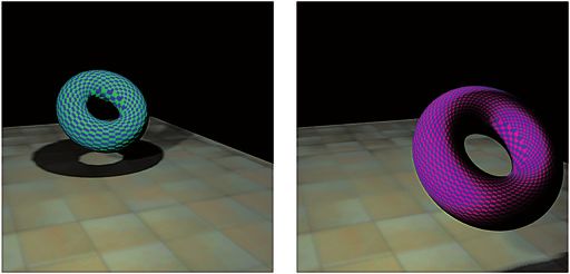
115:6        •       P. Djeu et al.

     approach also supports displacement mapping, which can be
     computed in the first phase of shading.
       However, the decision to decouple shading from visibility by
     evaluating shading in object space interacts in difficult ways with
     the decision to use multiresolution surfaces. We now have a sit-
     uation where shading may need to be performed at multiple res-
     olutions for any particular surface. Doing this is straightforward
     when visibility is coupled to shading, but less so once we de-
     couple them. This challenge is addressed by the detailed system
     design presented in Section 5.

4.3      Additional Key Decisions
There are two other important aspects of Razor’s design.
—Parallelize at a fine granularity and partially replicate accel-
 eration structure. In an interactive ray tracer, it is not possible                         Fig. 2. With discrete LODs, a ray may miss a surface completely if it
 to parallelize across frames as it is with batch renderers. In-                             changes the LOD that it is requesting at a point along the ray that is in
 stead Razor parallelizes at a finer granularity, assigning different                        between the surfaces produced by two discrete LODs.
 screen regions to different cores, and using SIMD within each
 core to parallelize across rays and across shading samples. To
 eliminate synchronization overhead for building the acceleration                            integrated system. In particular, the system architecture addresses
 structure, each core builds its own instance of the on-demand                               the key technical challenges presented in the previous section. While
 acceleration structure. We made this choice because it performed                            some elements of our system adapt well-known approaches, other
 better than a shared acceleration structure on the two-socket, 4-                           elements of the system are individually novel and require more de-
 core-per-socket platform with large caches that we used to run                              tailed explanation. Fortunately, the major components are familiar
 experiments. In particular, there is surprisingly little replication                        from any standard ray tracer: the ray/surface intersection technique,
 overhead, due to the fact that each instance of the acceleration                            the acceleration structure, and the shading system. We will describe
 structure is built on demand, and the fact that the detailed geom-                          these components one at a time.
 etry used by primary rays is mostly not replicated. However, this
 decision to replicate the acceleration structure is not fundamental
 to the Razor design; and in follow-on work using a simulated                                5.1    Multiresolution Ray/Surface Intersection
 architecture with less per-core cache we have configured Razor
 to share an acceleration structure across local groups of cores                             As discussed earlier, the ray/surface intersection problem is espe-
 [Govindaraju et al. 2008].                                                                  cially challenging in a system like Razor that uses ray-directed LOD
—Multiresolution geometry is generated by tessellating Catmull-                              rather than camera-directed LOD, since a single surface region may
 Clark subdivision surfaces on demand. Razor generates triangle-                             be represented at multiple resolutions within a single frame.
 based geometry at the desired resolution by adaptively tessellat-                              In order to reuse tessellations and associated vertex data and
 ing Catmull-Clark subdivision surfaces, then splitting each quad                            shading computations within a frame (as is needed when decoupling
 into two triangles. We made this choice based on best-known                                 shading from visibility) these computations must be generated and
 practices at the time for use of subdivision surfaces. If we were to                        cached for discrete levels of detail. Unfortunately, in a ray tracer,
 redesign the system now, we would consider using more recent                                naive discrete LOD approaches suffer from what we call the tun-
 innovations in subdivision surfaces [Loop and Schaefer 2008].                               neling problem (the name is inspired by the quantum mechanical
 Since subdivision is performed on demand, it would be possible to                           concept of tunneling). Figure 2 illustrates the simplest version of
 confine the triangles generated by tessellation to on-chip storage                          the problem. In the figure, the level of detail used for intersection
 and use, and Razor was designed to support this technique. The                              between the ray and the surface changes abruptly at a point along
 basic idea is to discard triangles when they are evicted from the                           the ray. This is a direct result of discretization and of the fact that
 cache rather than write them to off-chip DRAM. If a triangle turns                          the required LOD is a function of location along the ray. Unfortu-
 out to be needed later, it can be regenerated, as inspired by Pharr                         nately, the ray switches from wanting the fine version to wanting
 and Hanrahan [1996]. However, we have not yet implemented the                               the coarse version at a point along the ray which is after the in-
 cache management for this technique, and so currently triangles                             tersection with the coarse version but before the intersection with
 are written to off-chip DRAM when they are evicted from cache,                              the fine version. This causes the ray to pass through both versions
 generating spurious off-chip DRAM write traffic.                                            of the surface without any intersection being detected. This prob-
                                                                                             lem is closely related to LOD popping (the abrupt transition of an
5.     SYSTEM ARCHITECTURE                                                                   object from one LOD to another over the course of an animation),
                                                                                             and differs from other typical ray tracing artifacts. Unlike patch
So far, we have discussed the goals of Razor, the high-level de-                             cracking, where a gap forms between neighboring patches which
sign decisions that were made, and the key technical challenges                              have been adaptively refined to different LODs along their shared
presented by these high-level decisions. It is already clear that the                        border, holes produced by tunneling can appear even in the middle
individual design decisions interact with each other in complex                              of individual triangles. Unlike numerical precision problems, tun-
ways, as is typically the case for any sophisticated system.                                 neling holes can have significant geometric extent. A key challenge
   In this section we present the system architecture of Razor, which                        in ray tracing multiresolution surfaces is to design a technique that
combines and refines the high-level technical strategies already pre-                        avoids tunneling and patch cracking while satisfying other system
sented so that they are compatible with each other and form a single                         constraints.
ACM Transactions on Graphics, Vol. 30, No. 5, Article 115, Publication date: October 2011.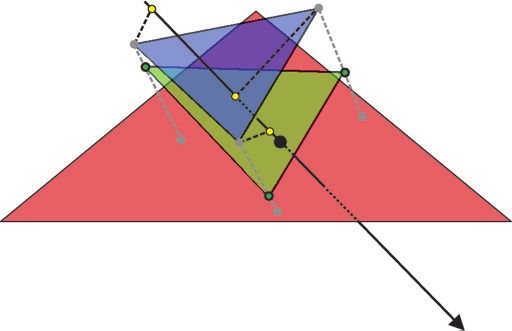
Razor: An Architecture for Dynamic Multiresolution Ray Tracing                               •      115:7

   5.1.1 Previous Work on Raytracing LOD. Some production
ray tracing systems (e.g., Tabellion and Lamorlette [2004]) rely
on manual per-shot tuning of LOD parameters to eliminate possi-
ble cracking artifacts; but interactive systems require an automatic
technique.
   Pixar’s production rendering system that hybridizes ray tracing
with REYES avoids tunneling and cracking by introducing some
additional constraints on tessellation based on the camera point
[Christensen et al. 2003, 2006]. Their system avoids tunneling for
ray traced secondary rays by choosing a discrete LOD for an entire
subpatch when the ray first enters the bounding box of that subpatch.
The bounding box is chosen such that all possible LODs for the sub-
patch are enclosed within it, thereby insuring that tunneling cannot
occur. However, for a large base patch such as ground terrain, this
technique then raises the question of how to choose the appropriate
sized subpatch at which to apply this technique. If the technique
is applied to the base patch, then each ray uses a single LOD for
the entire base patch, resulting in potentially severe overtessellation          Fig. 3. For each ray/triangle intersection test, the system generates a custom
and/or undertessellation in some portions of the patch. If the tech-             triangle that is specific to that ray. This custom triangle (green) is generated
nique is applied to some appropriately sized subpatch, then some                 by interpolating between triangles from two discrete levels of detail (blue and
mechanism is needed to insure that all portions of a ray choose the              red). The interpolation weight for each vertex is determined by projecting
same granularity of subpatch; otherwise tunneling could still occur.             the fine-triangle vertex (e.g., v1) onto the ray, computing the scale value at
Also, to make crack avoidance between subpatches tractable, it is                that point on the ray (yellow dot), and determining the fractional distance of
useful to insure that all rays intersecting a particular region of the           this scale value from the two discrete levels.
patch apply the technique to the same granularity of subpatch. To
address these issues, the Pixar system chooses the subpatch based                not make any guarantees about maintaining surface continuity, so
on the LOD used by the primary rays for that patch. More specif-                 cracks/holes are possible.
ically, the subpatch is the final subpatch (a.k.a. grid) produced by                In work subsequent to ours, Hanika et al. present a mulitiresolu-
the splitting operations of the REYES system. This choice avoids                 tion ray tracing system based on patch tessellation where LOD is
tunneling and also helps to insure consistency between primary                   set on a per-patch basis [Hanika et al. 2010]. Their system avoids
“rays” and secondary rays, but has the unfortunate side effect of                cracks by in effect giving the surface a finite thickness at coarser
preventing secondary rays from accessing a LOD coarser than a                    levels of detail. At a patch boundary where a finer level abuts a
2 × 2 tessellation of the subpatch, even if the original base patch              coarser level, the finer level is guaranteed to abut the thicker edge
would have been able to support a coarser LOD for the secondary                  of the coarser level. More specifically this is done by intersecting
rays. Thus, the LOD choices of the secondary rays are artifically                rays with small slabs (which are actually the boundaries of a BVH
constrained by the LOD choices of the primary rays even though                   node), whose extent is set such that it is guaranteed to include any
secondary rays often request LODs which are far coarser than those               finer-level tessellation of the surface, including any possible dis-
of primary rays.                                                                 placements. This LOD scheme shares the same advantages as our
   With Pixar’s approach, crack avoidance between patches be-                    scheme: it avoids cracks while being easy to parallelize.
comes complicated. The reason is that two secondary rays inter-
secting adjacent subpatches (grids) can choose different discrete                   5.1.2 Razor’s LOD Technique. For Razor, we developed a dif-
LODs, leaving the potential for cracks between the subpatches un-                ferent approach to LOD for ray tracing than that used by Chris-
less extra adjustments are made. Christensen et al. [2006] state                 tensen et al. that avoids cracking and tunneling, yet does not not
that the Pixar system makes these adjustments by moving vertices                 restrict the LOD used by secondary rays and facilitates fine-grained
at subpatch boundaries and/or inserting gap-filling polygons, but                parallelization by avoiding the need to exchange information be-
provide insufficient detail to understand exactly how the technique              tween neighboring patches or subpatches. This approach is used
works for secondary rays, where there is no canonical LOD for a                  for all rays, including primary rays. The new technique is a hybrid
subpatch as there is for primary rays. Our best guess is that a ray              between discrete and continuous approaches to LOD. The system
which is close to a boundary between subpatches computes the LOD                 generates discrete levels of detail but continuously interpolates (i.e.,
for both subpatches, and is intersected against gap-filling polygons             geomorphs) between the levels. There are a number of discrete lev-
which are generated for that particular pair of LODs. It is important            els of detail (up to fourteen in the prototype), each specified by
to realize that these gap-filling polygons can be different for differ-          a world-space edge length threshold. Each level is a distinct ver-
ent secondary rays, in constrast to the situation for primary rays,              sion of the entire scene that is targeted at the given edge length
where there is just a single set of gap-filling polygons. This class of          threshold. The subset of the geometry in each level that is actually
techniques for crack avoidance requires that the system be able to               needed is built on demand while the remainder is never constructed.
find all patches (or subpatches) that neighbor a particular subpatch.            The system interpolates between adjacent discrete levels on-the-fly
This need for neighbor information adds complexity to the system’s               to produce a unique surface for intersection testing against each
data structures and makes it more difficult to parallelize computa-              ray. The continuous interpolation avoids tunneling as well as other
tions efficiently at the granularity of subpatches or rays, particularly         LOD popping artifacts. Geomorphing has been used previously
when tessellation is performed lazily.                                           with camera-directed LOD to render terrain [Hoppe 1998], but we
   Yoon et al. [2006] have developed a multiresolution ray tracing               extend its use to ray-directed LOD.
system concurrently with ours. Their system targets massive static                  Figure 3 illustrates our technique for interpolating between dis-
models, focusing primarily on memory footprint reduction. It does                crete LODs. We refer to the adjacent discrete LODs as the fine mesh
                                                                           ACM Transactions on Graphics, Vol. 30, No. 5, Article 115, Publication date: October 2011.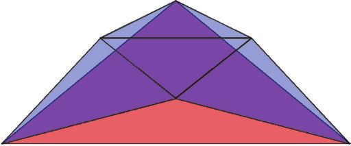
115:8        •       P. Djeu et al.

and the coarse mesh. This pair of adjacent discrete LODs is chosen                                 Table I. Comparison between LOD Methods Used by
from the larger set of discrete LODs so as to “bracket” the desired                                                Razor and PRMan
continuous LOD, using a mechanism to be described later in Sec-                                                                               PRMan      Razor
tion 5.2.6. The meshes in our system are generated via subdivision.                                   LODs available to secondary rays
The first step is to prepare a 1:1 correspondence between triangles                                      constrained by primary rays            yes       no
in the fine mesh and synthesized triangles lying on the coarse mesh.                                Information from neighboring patches
Each triangle in the fine mesh maps to a portion of a single triangle                                      required to avoid cracks             yes       no
of the coarse mesh. This property relies on the fact that we use                                      Dicing restricted to powers of two        no        yes
binary subdivision. The system pairs each vertex of the finer trian-                                  Requires multi-scale acceleration
gle with a point on the corresponding triangle in the coarse mesh,                                        structure and ray traversal           no        yes
thus defining the synthesized triangle lying on the coarse mesh that
corresponds to the fine-mesh triangle.
   The next step is to compute an interpolated triangle that represents                      (e.g., folding on itself, etc.), although it will still be crack-free. As
an interpolation between the fine-mesh triangle and the correspond-                          mentioned before, an additional limitation of this approach in its
ing synthesized triangle lying on the coarse mesh. The system                                current form is that it requires that each discrete LOD be constructed
produces this interpolated triangle by interpolating between vertex                          by power-of-two tessellation of the base patch (a.k.a. binary dicing),
positions in the fine mesh (three vf shown as v1, v2, and v3 in Fig-                         in order to allow the interpolation between coarse and fine triangles.
ure 3), and the corresponding points on the coarse surface (three vc ,                       As Christensen et al. [2006] point out, this requirement can result
which are not necessarily vertices). This interpolation is performed                         in tessellations that are finer than strictly needed. For systems that
independently for each vertex in the fine mesh, with a separate                              shade at micropolygon vertices as ours does, unnecessarily fine
interpolation weight used for each of the three vertices in a triangle.                      tesselations result in an increase in shading costs as compared to a
The interpolation weight for each vertex in the fine mesh is found                           tessellation at exactly the desired resolution. Table I summarizes the
by projecting the fine-mesh vertex onto the ray, yielding a distance                         differences between Razor’s LOD method and that of Christensen
along the ray t. With the ray defined by origin P and direction D:                           et al. [2006].
                                                                                                The technique we have just described allows us to intersect a ray
                             t = (vf − P) · D̂.                                (1)           with a blend of geometry from two adjacent discrete levels of detail.
Then, the blend weight b between the fine and coarse “vertices” is                           The blend weights are computed from a continuous scale function
computed from a continuous scale function defined along the ray                              along the ray. This scale function will be described in Section 5.2.6.
                                                                                             Note that the system must insure that the appropriate pair of discrete
        ts = start of this LOD transition, see Section 5.2.6,                  (2)           levels of detail is used; this requirement adds complexity to our
        te = end of this LOD transition, see Section 5.2.6,                    (3)           system and will be discussed along with the scale function.
             clamp(t, ts , te ) − ts
        t# =                         ,                                         (4)              5.1.3 Tessellation of Curved Surfaces. The design of Razor as-
                      te − t s                                                               sumes that a surface can be represented at multiple geometric reso-
        b = 3(t # )2 − 2(t # )3 ,                                              (5)           lutions, with each resolution composed of triangles. These multiple
                                                                                             representations of the surface are provided to the multiresolution
where the last two equations are implementing a “smoothstep”                                 ray/surface intersector. Razor generates its multiresolution geome-
function. The blend weight b is then used to interpolate between the                         try by adaptively tessellating curved surfaces to produce triangles.
fine and coarse “vertices” to produce a single interpolated vertex v.                        In its most common configuration, Razor uses Catmull-Clark sub-
                          v = bvf + (1 − b)vc                                  (6)           division patches [Catmull and Clark 1978] as the original represen-
                                                                                             tation of the curved surface. Input scenes are provided as geometry
Applying this process to all three vertices of the fine triangle                             meshes. Some of our input scenes were explicitly designed to be
produces a single, interpolated triangle that has been custom-built                          rendered as Catmull-Clark patches, while others were originally
for the incoming ray. Since this triangle is built specifically for this                     designed to be rendered as polygonal meshes so that Razor must
particular ray, it is discarded after the intersection test is complete                      consider the original mesh vertices to be control points for Catmull-
(see Figure 3).                                                                              Clark patches.
   This projection and interpolation step reduces the overall                                   Our implementation of Catmull-Clark subdivision has support
ray/triangle intersection problem to that of standard (nonmultireso-                         for textures, geometric creases, and texture creases [Halstead et al.
lution) ray/triangle intersection. The overall algorithm is quite effi-                      1993; Biermann et al. 2000]. Following the design described by
cient. The interpolation weights in this scheme are associated with                          Derose et al. [1998], the Catmull-Clark patches use a generic topol-
vertices, not triangles, so if both the fine and the coarse meshes are                       ogy representation (i.e., vertices, edges, faces) in regions of the
crack-free, the interpolated mesh is as well. This property relates                          mesh that contain extraordinary points or crease edges and a uni-
to a important point. The fact that each discrete level is a consis-                         form bicubic B-spline representation in regions of the mesh that
tent view of the entire scene makes it relatively easy to ensure that                        are completely regular [Lane et al. 1980; Peterson 1994]. The latter
level’s properties (e.g., that it is crack-free). Any such property that                     representation is preferable because it can be split or tessellated
is in turn preserved by vertex-by-vertex interpolation is therefore                          anisotropically; that is, it can be split into two subpatches along
preserved in the interpolated surface that is “seen” by a ray. There                         just one parametric direction, or tessellated at different rates in each
is some commonality between this approach and camera-directed                                of its two parametric directions. Support for anisotropic tessela-
LOD techniques for terrain [Luebke et al. 2003; Hoppe 1998].                                 tion is particularly useful since it mitigates the potential for high
   Note that the crack-free guarantee applies to a single ray, and that                      overtesselation from long, skinny original patches.
we currently make no guarantees about the relation between what                                 In most rendering systems, the purpose of adaptive tessellation is
geometry will be “seen” by one ray versus another. We also cannot                            to ensure that curved surfaces appear smooth, especially at silhou-
guarantee that a surface will not “misbehave” under interpolation                            ette edges. However, in Razor and REYES, where shading occurs
ACM Transactions on Graphics, Vol. 30, No. 5, Article 115, Publication date: October 2011.
Razor: An Architecture for Dynamic Multiresolution Ray Tracing                               •      115:9

at vertices, adaptive tessellation has the even more important pur-
pose of insuring that the shading rate is sufficient. Unfortunately,
Catmull-Clark subdivision is complex and cannot be performed
anisotropically near extraordinary points, sometimes leading to sig-
nificant computational cost. To control for these effects, we im-
plemented a second tessellation subsystem in Razor which has the
sole goal of generating vertices at a sufficient density for shading
without the complexities of Catmull-Clark subdivision. This second
tessellation subsystem treats each mesh element as a bilinear patch
(i.e., as close to planar as one can get with four vertices). These
bilinear patches can be refined by either splitting them in half along
one of their parametric directions or by converting them into a tes-
selated grid where each parametric direction has its own tesselation
rate. The bilinear system removes much of the overhead of Catmull-              Fig. 4. A torus modeled as a Catmull-Clark subdivision surface. As the
Clark subdivision: tessellation is inexpensive and fully adaptive in            viewpoint changes, the number of subdivision refinement iterations in-
both parametric directions; and it is simple to compute a very tight            creases or decreases, as determined by the ray differentials. (Left) The
bounding box for a patch. Evaluating Razor in its bilinear tessel-              far viewpoint requires fewer iterations. (Right) The near viewpoint requires
lation mode allows us to measure the cost of shading at vertices                more iterations.
without the constraints imposed by Catmull-Clark subdivision.
   Since both tessellation techniques perform their tesselation adap-           camera. This combination of capabilities is, to our knowledge, not
tively, it is necessary to prevent or fix cracks between adjacent               present in any previous ray tracer.
patches. With bilinear tessellation, patch borders are always linear,              For example, Figure 4 shows two views of a torus represented as
so no explicit crack fixing is needed even when the tesselation rates           a Catmull-Clark subdivision surface. As the torus moves towards
of neighboring patches do not match. With Catmull-Clark patches,                the camera, it is refined until it is sufficiently well tessellated for the
there is the potential for cracking, so an explicit effort must be              current viewpoint. The number of refinement iterations is governed
made to avoid cracks. Like older versions of PhotoRealistic Ren-                by the ray differentials of the primary rays. As the torus moves away
derMan [Apodaca and Gritz 2000], Razor restricts the size of grids              from the camera, it is refined for fewer iterations. In both cases,
in the Catmull-Clark system to powers of two (binary dicing) to                 subdivision refinements are performed adaptively and the surface
simplify the process of finding corresponding vertices along the                remains crack-free, even while each primary ray is processed in
border. When two patches abut and one tessellates at 2× the rate                isolation, without knowledge of its neighbors.
of the other, cracks are avoided by moving each extra edge ver-                    We encourage the reader to review the last segment of the video
tex to lie on the straight line between its neighbors on the edge               that accompanies this article (accessible at the ACM Digital Library)
[Clark 1979]. It is important to note that this technique results in            for an example of the multiresolution properties of Razor over the
T-junctions which are generally considered to be a potential source             course of an animation. We show that the surface tessellation rate
of pinhole artifacts, although we have not observed any such arti-              changes continuously from viewpoint to viewpoint, resulting in an
facts in our limited tests. The decision process for this technique             artifact-free use of multiresolution. Our video also demonstrates that
is performed at each subdivision step, and is entirely local, using             objects are similarly well-behaved when they are viewed indirectly,
only information from the patch under consideration, and specif-                for example, via reflection rays. (Please note that some parts of
ically from the relevant edge of that patch. No information from                the video are generated in batch rendering mode; see Figure 8 for
the neighboring patch is required, facilitating parallelism and on-             performance information).
demand tessellation. The procedure is similar to that described by
Owens et al. [2002]. Moreton discusses the watertight tessellation
                                                                                5.2     Dynamic Multiresolution Acceleration Structure
problem in detail and shows that it is possible to guarantee perfectly
watertight tessellation [Moreton 2001].                                         As mentioned earlier, Razor builds its acceleration structure on de-
   Different approaches to ray tracing of subdivision surfaces have             mand, from geometry stored in a scene graph. The scene graph is
been used in other systems. In Razor, a patch (or subpatch, if the              mostly persistent from frame to frame, while the multiscale kd-tree
patch has been split) is completely tessellated and stored once the             acceleration structure is rebuilt every frame. We will now discuss
ray penetrates its bounding volume. The tessellation criteria is adap-          the scene graph in more detail. The upper levels of the scene graph
tive, and cracks are avoided by adjusting the vertex positions of the           are persistent, and are comprised of internal nodes which provide
tessellated polygons. The ShaoLin system [Müller et al. 2003] uses             hierarchical structure to the scene graph, and leaf nodes which con-
a more complex adaptive scheme, with tighter bounds tests based on              tain geometry in the form of one surface patch per leaf node. This
projection of the ray onto a test plane. The ShaoLin system relies              persistent portion of the scene graph may be updated in response to
on additional stitching/gap polygons to prevent cracks, and does                animation, simulation, or user input just as with any traditional scene
not store/cache any results. Benthin et al’s interactive system tessel-         graph system. The lower levels of the scene graph are added below
lates on-the-fly (no storage/caching) and avoids the complications              the persistent leaf nodes, and contain split and/or tesselated patches
of adaptive subdivision by always subdividing patches a constant                that are constructed during the course of rendering a frame. The
number of times [Benthin et al. 2004].                                          construction of these transient nodes is performed on demand, and
                                                                                is triggered by rays that require tessellated geometry at a particular
   5.1.4 Implications of Multiresolution Ray Tracing. By using a                level of detail. These lower parts of the scene graph and all accel-
per-ray multiresolution framework, Razor effectively uses multires-             eration data structures in the system are rebuilt from scratch every
olution geometry that (1) transitions continuously between discrete             frame. Hierarchical bounding volumes are maintained throughout
scales and (2) allows rays to independently choose their desired                this extended scene graph. The relationship between the scene graph
level of detail, without restrictions imposed by the position of the            and the multiresolution acceleration structure is shown in Figure 5.
                                                                          ACM Transactions on Graphics, Vol. 30, No. 5, Article 115, Publication date: October 2011.
You can also read


