REVIEW ARTICLE Advances in SPECT camera software and hardware: Currently available and new on the horizon
←
→
Page content transcription
If your browser does not render page correctly, please read the page content below

REVIEW ARTICLE

          Advances in SPECT camera software and
          hardware: Currently available and new on the
          horizon
          E. Gordon DePuey, MD

                      INTRODUCTION                                     significantly decreased injected radiopharmaceutical
                                                                       doses.
     A long-standing limitation of radionuclide myocar-
                                                                           There have been several comprehensive reviews
dial perfusion SPECT is its relatively lengthy acquisition
                                                                       and editorials published highlighting innovations in
time, as compared to stress echocardiography and
                                                                       cardiac SPECT hardware and software.5-9 I hope the
cardiac CT. The American Society of Nuclear Cardiol-
                                                                       present review will serve to reinforce the importance
ogy (ASNC) and the Intersocietal Commission for the
                                                                       and clinical significance of these technical advance-
Accreditation of Nuclear Medicine Laboratories
                                                                       ments. Of note, advancements in hybrid SPECT/CT
(ICANL) have rightfully insisted that acquisition times
                                                                       imaging are not covered in the present review.
not be decreased below those set forth in the ASNC
Guidelines so that adequate image counting statistics are
maintained, thereby maintaining test sensitivity and                              TECHNICAL ADVANCEMENTS
minimizing artifacts associated with low count density
studies. New software methods and new innovative                       New Software Methods
hardware described below, however, now allow for
                                                                            New SPECT reconstructions software methods have
significantly shortened SPECT acquisition times without
                                                                       preserved or improved SPECT image quality despite
a decrease in image quality.
                                                                       lower count statistics. Consequently, SPECT acquisition
     More recently, the media, the public, and the
                                                                       time may be shortened. Alternately, the injected radio-
medical community have drawn attention to patient
                                                                       pharmaceutical dose may be decreased, thereby
radiation exposure associated with radiographic, nuclear
                                                                       decreasing patient radiation exposure. These methods,
medicine, and nuclear cardiology procedures and the
                                                                       described below, are all now commercially available.
potential-associated patient risk.1,2 The radiology and
                                                                       They are available on new computer systems, and some
nuclear imaging communities have responded rapidly
                                                                       may also be implemented on older scintillation camera
and definitively by implementing a variety of guidelines
                                                                       systems.
to decrease patient radiation exposure and to avoid
                                                                            Iterative reconstruction. Iterative reconstruc-
exposure in higher risk patient populations: Image
                                                                       tion has been available on the nuclear medicine
Gently, Image Wisely, Choosing Wisely, and the ASNC
                                                                       computer systems for over a decade, although many
Patient-Centered Imaging Guidelines,3 among others.
                                                                       users have hung tenaciously to an older processing
ASNC has set a goal to decrease patient radiation
                                                                       method, filtered backprojection (FBP). FBP basically
exposure associated with myocardial perfusion SPECT
                                                                       suppresses high-frequency image data, thereby decreas-
to \9 mSv per entire study in 50% of patients by 2014.4
                                                                       ing noise. However, in doing so the technique results in
The new software and hardware methods described
                                                                       image blurring, often obscuring small perfusion abnor-
below will help us achieve this goal by providing the
                                                                       malities and rendering the images of both objects, i.e.,
ability to maintain or improve SPECT image quality
                                                                       the myocardium and perfusion defects indistinct. The
with the lower image counting statistics associated with
                                                                       smoother the filter, i.e., the lower the critical frequency
                                                                       and the higher the order, the greater the degree of image
                                                                       blurring and the poorer the diagnostic sensitivity in
                                                                       detecting perfusion abnormalities. In contrast, iterative
From the St. Luke s Hospital, Nuclear Medicine, New York, NY.          reconstruction provides an estimated reconstruction
Reprint requests: E. Gordon DePuey, MD, St. Luke’s Hospital, Nuclear   volume from which estimated projections are derived.
  Medicine, New York, NY; edepuey@chpnet.org.                          The estimate may be simply a uniform flood field or a
J Nucl Cardiol                                                         more complex heuristic algorithm with an estimate of
1071-3581/$34.00
                                                                       the expected configuration of the heart. Actual measured
Copyright Ó 2012 American Society of Nuclear Cardiology.
doi:10.1007/s12350-012-9544-7                                          SPECT projection data are compared to the estimated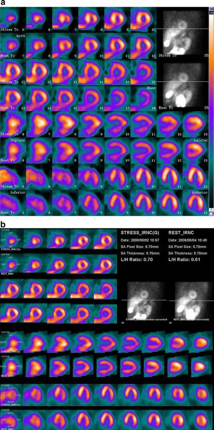
DePuey                                                                                      Journal of Nuclear Cardiology
      Advances in SPECT camera software and hardware

projections. Based upon the ‘‘error’’, i.e., the difference   Figure 1. A This low-dose rest/high-dose stress Tc-99m c
between the estimated and the measured projection             sestamibi study, performed in an obese patient, was processed
                                                              with FBP. Reconstructed tomograms are technically subopti-
information, the estimated projection is updated. This        mal with considerable noise and indistinct definition of the
process is repeated until the estimated and the measured      myocardial borders. Both at stress and at rest there is
projections converge, resulting in an implicit recovery of    considerable tracer uptake in the left lobe of the liver, which
resolution. The initial version of iterative reconstruction   lies in the x-plane of the inferior wall of the left ventricle. The
was Maximum Likelihood Expectation Maximization               fixed inferior perfusion defect could be secondary either to scar
                                                              or a Ramp filter artifact. B The same study was processed with
(MLEM), whereby individual iterations were repeated           OSEM iterative reconstruction. SPECT image quality is
until data converged. Subsequently, with higher speed         significantly improved with less noise and sharper definition
computers Ordered Subset Expectation Maximization             of the myocardial borders. The inferior perfusion abnormality
(OSEM) has become the reconstruction method of                is resolved, indicating that it was a Ramp filter artifact since
choice, whereby data are grouped into subsets, allowing       OSEM does not incorporate the Ramp filter. Courtesy Gordon
                                                              DePuey, St. Luke’s-Roosevelt Hospital, New York, NY.
more rapid and accurate data convergence.
     Myocardial perfusion SPECT images reconstructed
with OSEM are of higher quality than those processed          likelihood that Compton-scattered photons will be
with FBP. Perfusion defects, anatomic variants such as        accepted progressively increases. For these reasons
physiologic apical thinning and prominent posterior           spatial resolution of a voxel/object decreases with
papillary muscles, and the right ventricular myocardium       distance from the camera face. Therefore, it has always
are better visualized with OSEM. Likewise, image              been emphasized that when a patient is positioned for
contrast is improved, thereby better defining the left        myocardial perfusion SPECT, the face of the scintilla-
ventricular endocardial borders. Although differences in      tion detector should be as close as possible to the
FBP and OSEM may be only slight in high count density         patient’s chest wall. Likewise, an elliptical orbit is
myocardial perfusion SPECT scans, in lower count              preferable because it allows the camera head to more
density studies the improvement with OSEM is often            closely approximate the chest wall in all projections.
clinically significant. Another advantage of OSEM is          The magnitude of this loss of resolution is directly
that the Ramp filter, inherent to FBP, is not employed,       proportional to the width of the collimator hole and
thereby minimizing the possibility of a Ramp filter           inversely proportional to the hole length (Figure 3).
artifact, i.e., an artifactual decrease in inferior left      Septal penetration of photons is another cause of
ventricular myocardial count density when intense tracer      decreased the resolution of a parallel-hole collimator.
concentration is present in extracardiac structures in the    However, for the relatively low-energy isotopes, Tc-
x-plane of the left ventricle (Figure 1). However, of         99m and Tl-201, used for myocardial perfusion imaging
note, for most commercially available implementations         the degree of septal penetration is minimal.
of OSEM, a post-processing filter is employed to further           This distance-dependent collimator-detector blur,
improve image quality. Therefore, the Ramp filter             dependent upon the shape of the holes, their dimensions,
artifact may not be eliminated entirely.                      and the thickness of the septa for each individual
     Resolution recovery. The high-resolution, par-           collimator has a major influence on image resolu-
allel-hole collimator used for myocardial perfusion           tion.10,11 It is the main factor affecting the resolution and
SPECT maintains spatial resolution by accepting pho-          noise properties of nuclear medicine images. In recon-
tons emitted from the myocardium, traveling directly          structed SPECT images, these effects are strongly
perpendicular to the face of the camera and the parallel      influenced by the applied reconstruction algorithm and
holes of the collimator. Photons emanating from voxels        its parameters. Resolution recovery models the physics
not directly perpendicular to the collimator hole are         and geometry of the emission and detection processes. It
attenuated by the collimator’s lead septa. Photons            is thereby a means to compensation for the collimator-
emanating from these voxels may undergo Compton               detector response (CDR) in iterative reconstruction.12-14
scattering and may also subsequently travel perpendic-        The CDR consists of four main components: intrinsic
ular to the collimator hole. These are eliminated by the      response (the system without a collimator) and the
pulse height analyzer, which rejects photons losing more      geometric, septal penetration, and septal scatter compo-
than 10%-15% of their initial photon energy. However,         nents of the collimator parameters. By including an
these advantages of the parallel-hole collimator are          accurate model of CDR function in an iterative SPECT
progressively compromised the more distant the voxel is       reconstruction algorithm, compensation for the blurring
from the camera face (Figure 2). The greater the              effect may be included in the iterative reconstruction
distance of object from the camera face, the greater          process, resulting in improved spatial resolution. For
the likelihood that photons from adjacent voxels will         each combination of acquisition system, radiopharma-
pass through the parallel-hole collimator. Likewise, the      ceutical, and particular acquisition protocol, the CDR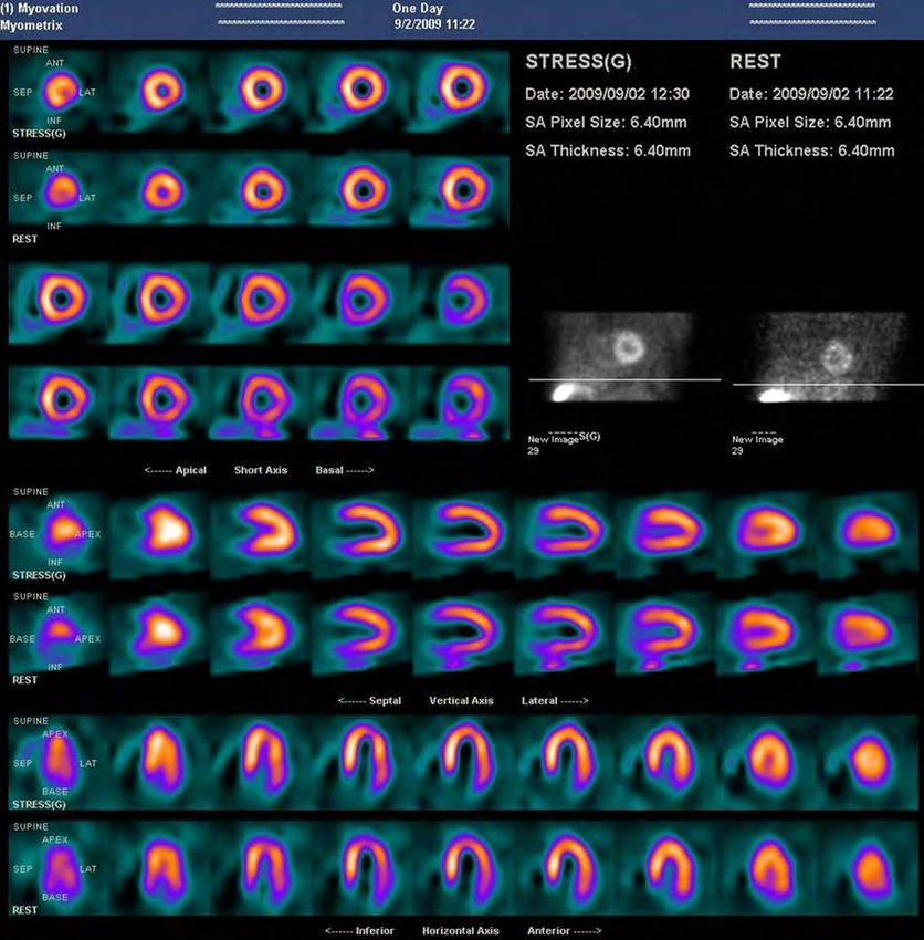
Journal of Nuclear Cardiology                                          DePuey
                                Advances in SPECT camera software and hardware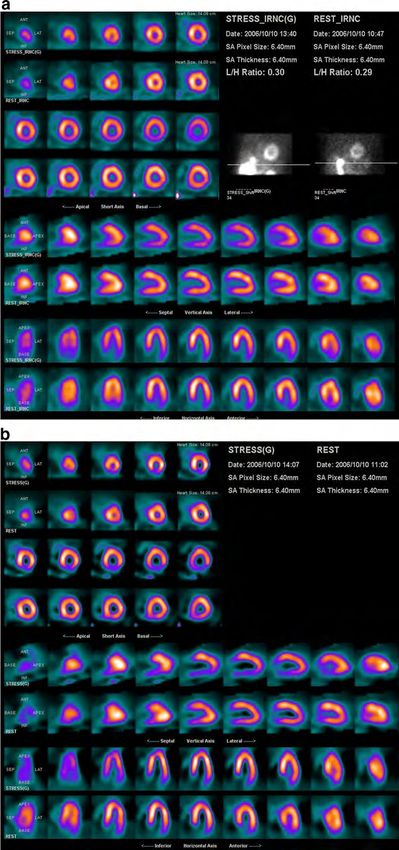
DePuey                                                                                                        Journal of Nuclear Cardiology
       Advances in SPECT camera software and hardware

An object close to the collimator will   An object farther from the collimator
   have less blur.                          will have more blur.

Figure 2. Depth-dependent loss of resolution. When an object
is further from a parallel-hole collimator, photons emanating
from the object pass through a greater number of parallel holes
of the collimator, thereby blurring the object and decreasing                    Figure 3. Loss of resolution with the depth from the parallel-
spatial resolution. Courtesy Yossi Srour, UltraSPECT Ltd.                        hole collimator depends upon the collimator hole characteris-
                                                                                 tics. For a collimator with narrow, long holes (left) the loss of
                                                                                 resolution with depth is less than that of a collimator with
function provides the probability that a photon emitted                          short, wide holes (right). Septal penetration of photons also
from any point of the imaged object will contribute to a                         contributes to image blurring (left), although this factor is
                                                                                 minor for low-energy isotopes such as Tc-99m.
pixel of the resulting image. Accurate predictions of the
geometric response function for various collimator
designs have been derived. Specifically, during iterative
reconstruction each voxel is reconstructed according to
the collimator’s geometry. Pixel weights are calculated
analytically, taking into account the solid angles sub-
tended by the collimator between each detector pixel
and each body voxel. This is accomplished by knowing
the CDR for each particular scintillation camera/colli-
mator system.
     To implement resolution recovery acquisition
parameters including the center-of-rotation and the
collimator-to-voxel distances for every projection view
acquired must be known. Additionally, in order to apply
pixel weighting appropriately to the image matrix,                               Figure 4. During iterative reconstruction data are modified in
which includes the heart and surrounding body struc-                             each reconstructed voxel according to the collimator’s geom-
                                                                                 etry. Pixel weights are calculated analytically, taking into
tures, the distance from the detector to the patient’s body                      account the solid angles subtended by the collimator between
must be determined. Newer cameras automatically                                  each detector pixel and each body voxel. Also, in order to
provide this distance in the acquired parameters for                             apply pixel weighting appropriately to the image matrix, the
each angular position. However, for cameras that do not                          distance from the detector to the patient’s body is accounted
provide this distance automatically from the acquisition                         for.
parameters, a simple segmentation algorithm may be
applied to the projections to estimate the detector-to-                          recovery method can be implemented on both newer
body distance.                                                                   and older cameras.
     One resolution recovery method, incorporated into                                Therefore, resolution recovery yields images of
Wide Beam ReconstructionÒ (WBRÒ) (UltraSPECT,                                    improved spatial resolution and with less noise as
Ltd.), models the CDR and the physics and geometry of                            compared to conventional techniques.15 Clinical images
the emission and detection processes.15 As described                             of lower count density acquired with resolution recovery
above, the shape of the holes, their dimensions, and the                         have been demonstrated to be equivalent or superior to
thickness of the septa for each individual collimator                            those acquired with conventional SPECT imaging,
have a major influence on image resolution. Therefore,                           allowing for reduced SPECT acquisition time or reduced
during iterative reconstruction data are modified in each                        injected radiopharmaceutical dose (see below).
reconstructed voxel according to the collimator’s geom-                               Noise compensation. Nuclear imaging data
etry. Pixel weights are calculated analytically, taking                          are inherently noisy due to relatively poor counting
into account the solid angles subtended by the collimator                        statistics. Low count density myocardial perfusion
between each detector pixel and each body voxel                                  SPECT images are characterized by noise, which has
(Figure 4). With knowledge of various scintillation                              similar or higher magnitude compared to the high-
detector systems and collimators, this resolution                                frequency portion of the true myocardial data. As
Journal of Nuclear Cardiology                                                                                     DePuey
                                                                           Advances in SPECT camera software and hardware

described above, FBP eliminates high-frequency data,              regularizes the likelihood objective function by adding a
thereby ‘‘smoothing’’ (i.e., blurring) the image. This            Gaussian component. Higher weight to the Gaussian
filtering results in decreased image contrast, decreased          component results in suppressed high-frequency com-
spatial resolution, and potentially decreased diagnostic          ponents present in the projections, due to its fast
sensitivity in detecting perfusion and regional wall              vanishing tail. Higher weighting of the Poisson compo-
motion abnormalities. In contrast, with noise compen-             nent results in recovery of high-frequency signal, or
sation methods signal-to-noise values are determined by           enhancement of noise if no appropriate weight is given.
the resolution and smoothness desired in the final                The balance between the two is determined adaptively
cardiac SPECT image. High-frequency components of                 and automatically according to the data analysis and
the image are suppressed while resolution is maintained           desired smoothness. The reconstruction is iterative and
(Figure 5).                                                       automatic with all noise compensation parameters
      One noise compensation technique, WBRÒ (Ultra-              selected automatically and with no post-filter applied.
SPECT, Ltd.), suppresses noise and enhances the signal-           The smoothness of the image is guided by the applica-
to-noise ratio (SNR) by modeling the statistical charac-          tion’s target SNR without applying filters during or
teristics of the emission process and of the detected             post-reconstruction (Figure 6). For the WBRÒ method,
data.16 It accounts for the Poisson distribution of the           incorporating iterative reconstruction, resolution recov-
emission data, as well as for the noise in the acquired           ery, and noise compensation, the spatial resolution
data. To preserve or even enhance the SNR, WBRÒ                   (FWHM) for three line sources with scatter was reported
                                                                  to be 5.1 mm, as compared to 10.2 mm (coefficient of
                                                                  variation = 3.7% for both) for standard FBP processing.
                                                                  Contrast resolution from Data Spectrum phantom exper-
                                                                  iments (with scatter) was 0.67 compared to 0.53 for FBP
                                                                  (coefficient of variation = 12% for both).15
                                                                       Of note, resolution recovery algorithms themselves
                                                                  may result in accentuation of noise in reduced-time
                                                                  acquired projections. This has a detrimental effect on
                                                                  image quality. One method, adopted in the General
                                                                  Electric EvolutionÒ software suppresses the impact of
                                                                  noise by incorporating a Maximum A Posteriori (MAP)
                                                                  Algorithm.17 The scheme used is a modified one step
                                                                  late (OSL) algorithm using a Green prior optimized for
                                                                  each clinical protocol, and for gated and attenuation
                                                                  corrected image.18 The last iteration is performed using
                                                                  a Median root prior.19 This scheme was found to give an
                                                                  image of equal or superior quality on clinical studies and
                                                                  on physical phantom data.20

Figure 5. Comparison of the effects of filtering and noise
compensation on a myocardial perfusion count-rate profile. A
representative profile across an object demonstrates consider-
able high-frequency noise. Filtering, i.e., smoothing, the data   Figure 6. Tomographic slice through the Jaszczak phantom
(top) decreases noise, but at the same time considerably          containing low-level Tc-99m background tracer concentration
decreases image resolution and contrast. On the other hand,       and spheres of various diameters containing higher level
with noise compensation (bottom) signal-to-noise values are       activity. With FBP reconstruction (left) there is moderate noise
determined by the resolution and smoothness desired in the        in the background area, and the edges of the spheres are
final SPECT image. High-frequency components of the image         blurred. With WBRÒ reconstruction (right), incorporating
are suppressed while resolution and contrast are maintained.      resolution recovery and noise compensation, background noise
Concept courtesy of Ernest Garcia, Emory University, Atlanta,     is suppressed, and resolution and contrast of the spheres are
GA.                                                               increased15.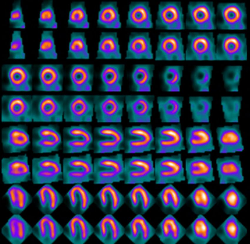
DePuey                                                                                  Journal of Nuclear Cardiology
      Advances in SPECT camera software and hardware

     Vendors of conventional SPECT cameras as well as         the cardiac cycle. Left ventricular dyssynchrony
the new, innovative cameras described below have all          assessed by this technique in 75 heart failure patients
adopted advanced software processing methods, includ-         was compared to echocardiographic tissue Doppler
ing iterative reconstruction, resolution recovery, and        imaging and was found to correlate well (r = 0.89,
some type of noise compensation. These software               P \ .0001).22 It has been reported that left ventricular
packages include AstonishÒ, Phillips; ShineÒ, Segami;         dyssynchrony measured by this method is useful to
EvolutionÒ, General Electric Medical Systems; 3-D             predict which patients will respond to cardiac resyn-
FlashÒ, Siemens Medical Solutions; n-SPEEDÒ, Digi-            chronization therapy (CRT).23 Using a phase histogram
rad, Inc.; and proprietary software developed by General      bandwidth of approximately 140°, this method demon-
Electric for the Discovery 530c camera and by Spectrum        strated a sensitivity of 70% and specificity of 74% in
Dynamics for the D-SPECT camera. Users should be              predicting patient response to CRT. Although this
aware that these software programs each use different         radionuclide method is quite promising, there have been
reconstruction algorithms, so results are by no means         parallel advancements in echocardiography, magnetic
identical.                                                    resonance imaging, and cardiac computed tomography
     Pre-determined SPECT acquisition times to                in assessing left ventricular dyssynchrony and patient
obtain optimal counts. The introduction of dual-              response to CRT.24
head cameras more than a decade ago allowed us to halve
acquisition times as compared to acquisition times for
                                                              Hardware Developments
studies performed on older single-head cameras. Since
their introduction, however, cardiac SPECT protocols               Optimized detector geometry and focused
have been rather rigid with regards to image acquisition      collimation.
times. For larger patients with soft tissue attenuation            Dedicated sodium iodide detector cardiac SPECT
resulting in low count density studies ‘‘weight-based         cameras. Well over a decade ago scintillation camera
dosing’’ was recommended to increase cardiac SPECT            designs were modified to better perform dedicated car-
counting statistics. However, by increasing the radio-        diac imaging. Phillips introduced the CardioMDÒ
pharmaceutical dose, patient radiation exposure is            camera with two 90°-angled detectors that could be
likewise increased. As an alternative to increasing the       positioned close to the patient’s chest wall to optimize
radiopharmaceutical dose, it is possible to increase          detector geometry and minimize detector-to-voxel
SPECT acquisition time in cooperative patients. Newer         blurring. The open gantry design was patient-friendly,
‘‘smart’’ cameras allow optimal SPECT acquisition times       even for most claustrophobic patients. The design was
to be predetermined in such patients. For example,            compact, allowing the small footprint camera to fit
TruACQÒ software available on the Digirad CardiusÒ            easily into an 80 9 100 room. General Electric intro-
camera determines the count rate from regions of interest     duced the OptimaÒ camera, with similar advantageous
manually placed over the heart on each of its three           characteristics. Both of these cameras could be equipped
detectors. An acquisition time is then pre-determined         with rod-source attenuation correction (AC). Subse-
which will result in 22,000 counts in the heart (in the LAO   quently, dedicated cardiac SPECT cameras were
projection) at stress and 10,000 counts at rest. The camera   introduced to accommodate larger patients. One exam-
operator can accept or reject this suggested acquisition      ple is the General Electric VentriÒ camera with two
time, depending upon the patient’s tolerance. By this         independent detectors positioned in a 90° geometry,
means optimal counting statistics can be obtained in larger   mounted on a ring gantry. Patients are comfortably
patients without increasing the radiopharmaceutical dose.     positioned on an imaging palate, sturdy enough to
     Phase analysis. Innovative software has been             accommodate the patients up to 440 pounds, with sup-
developed to measure left ventricular systolic dyssyn-        ports engineered to relieve pressure on the arms, knees,
chrony using phase analysis of gated myocardial               low back, and neck. The palate slides into the ring
perfusion SPECT.21 Increasing myocardial counts dur-          detector of the gantry, and the detectors are then posi-
ing ventricular systole correlates with regional left         tioned close to the chest wall in an optimal geometry for
ventricular wall thickening and may be used to assess         cardiac SPECT. The advantages of such dedicated car-
the pattern of systolic contraction. Data from the entire     diac SPECT cameras are considerable. However, for a
myocardium are used to generate a phase distribution          general Nuclear Medicine laboratory they lack the
map that may be displayed as a histogram or polar map.        flexibility to perform other non-cardiac scans.
By means of a sampling theorem, temporal changes in                Dedicated upright and semi-reclining cardiac
left ventricular myocardial contraction can be assessed       SPECT cameras. Patients are positioned upright with
using only 8 frames per cardiac cycle. This method            the Digirad camera and semi-upright/semi-reclining
provides temporal resolution equivalent only 1/64th of        with the Siemens C-CamÒ camera and the Data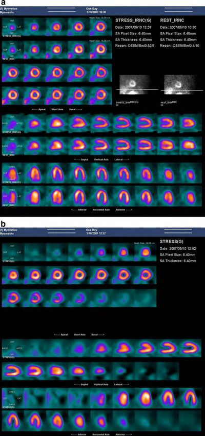
Journal of Nuclear Cardiology                                                                                  DePuey
                                                                        Advances in SPECT camera software and hardware

Spectrum D-SPECTÒ camera. Each of these cameras                compared to body-centered orbits, and the severity of
has a small footprint and is designed for patient comfort.     artifacts is reduced27 (Figure 7). New collimator designs
Upright or semi-reclining positioning allows the dia-          and other new cameras, described below, including the
phragm to move inferiorly, thereby decreasing                  Spectrum Dynamics D-SPECTÒ camera and the General
diaphragmatic attenuation and Compton scatter from             Electric Discovery 530cÒ camera, also incorporate car-
sub-diaphragmatic structures. A second advantage of            diocentric SPECT.
upright or semi-upright positioning is that pendulous               Cardio-focused collimation. A cardio-focused
breasts are less likely to assume different positions in the   collimator, IQ SPECTÒ, has been developed by Siemens
stress and the rest SPECT acquisitions, a problem              Medical Solutions to improve the efficiency of myo-
occasionally encountered with supine SPECT, resulting          cardial perfusion imaging using conventional, large
in ‘‘shifting’’ breast artifacts mimicking ischemia.           field-of-view SPECT and SPECT/CT systems (Fig-
Photon attenuation artifacts involving the inferior wall       ure 8).28,29 This variable-focus collimator is designed to
due to an overlying pendulous left breast, however, are        magnify the region of the myocardium and its immedi-
more likely with upright and semi-upright/reclining            ate surroundings by means of converging collimation,
patient positioning. Patient motion was problematic for        while keeping the entire torso in the field-of-view by
the long acquisition times required for earlier single-        morphing the collimator holes to a near parallel-hole
head versions of the Digirad upright camera. However,          geometry at the edges of the collimator, thereby avoid-
in the most recent release of the multi-head camera            ing truncation. There are 48,000 hexagonal holes, each
shorter acquisition times combined with Velcro straps/         1.9 mm in diameter and 40 mm in length. Spatial res-
binders around the patient’s waist and chest effectively       olution progressively increases from the face of a
minimize motion, particularly in the Y- and Z-directions.      camera to the cardiac ‘‘sweet-spot’’ at 28 cm. The scan
     Cardiocentric SPECT. Conventional myocardial              orbit is cardiocentric, 28 cm from the center of rotation,
perfusion SPECT performed with a single- or dual-head          as determined by the operator, so that the heart is
scintillation camera, as described above, employs a            maintained in the region of highest magnification
body-centered orbit. However, SPECT images acquired            throughout the scan. A scanning arc of 104° with 6°
with such a 180° body-centered orbit may have signifi-         angular steps is used for each of the two 90°-angled
cant erroneous inhomogeneity and may overestimate              camera heads.
defect size, particularly when the target object is off the         Since the collimator has a response that is not only
center of the orbit, as is commonly the case in clinical       distance-dependent but also variable across the face of
cardiac imaging.25 Although, elliptical body-centered          the collimator, it is crucial to accurately model both the
orbits minimize the distance between the heart and the
detector in all tomographic projections, thereby mini-
mizing distance-dependent image blurring and scatter,
SPECT artifacts, particularly those at the left ventricular
apex, may be more severe in scans using elliptical orbits
than in those from circular acquisitions.26
     Newer camera designs incorporate ‘‘cardiocentric’’
SPECT orbits. Detector design and/or translation of
either the camera heads or the patient before or during
SPECT acquisition allow the heart to remain in the
center of the field-of-view. For example, the Digirad
CardiusÒ camera uses a triple-head geometry. The
patient sits on a translating chair. Immediately prior to
the SPECT acquisition the patient’s heart is positioned
in the center of the field-of-view of each detector. The
detector heads are pushed in as close as possible to
the patient’s chest to optimize image quality. For the         Figure 7. A data spectrum phantom, filled with Tc-99m, with
SPECT acquisition the chair rotates 67.5°, allowing the        a full-thickness insert in the posterior wall was imaged with a
triple-head camera to acquire data in a 202.5° cardio-         180° cardio-centric orbit (left) and again with an off-center
centric orbit. This triple-head configuration used in          orbit (right), simulating a body-centered orbit. The radius of
                                                               rotation of the orbit was progressively increased from 18 to 23
combination with 3-dimensional OSEM nSPEEDÒ                    to 28 cm. The posterior defect is better resolved using a cardio-
reconstruction enables emission scans to be performed          centric orbit, particularly with a smaller camera radius of
up to four times faster than with conventional dual-           rotation. Courtesy, Richard Conwell and Chuanyong Bai,
head SPECT systems.27 Image quality is improved as             Digirad Inc.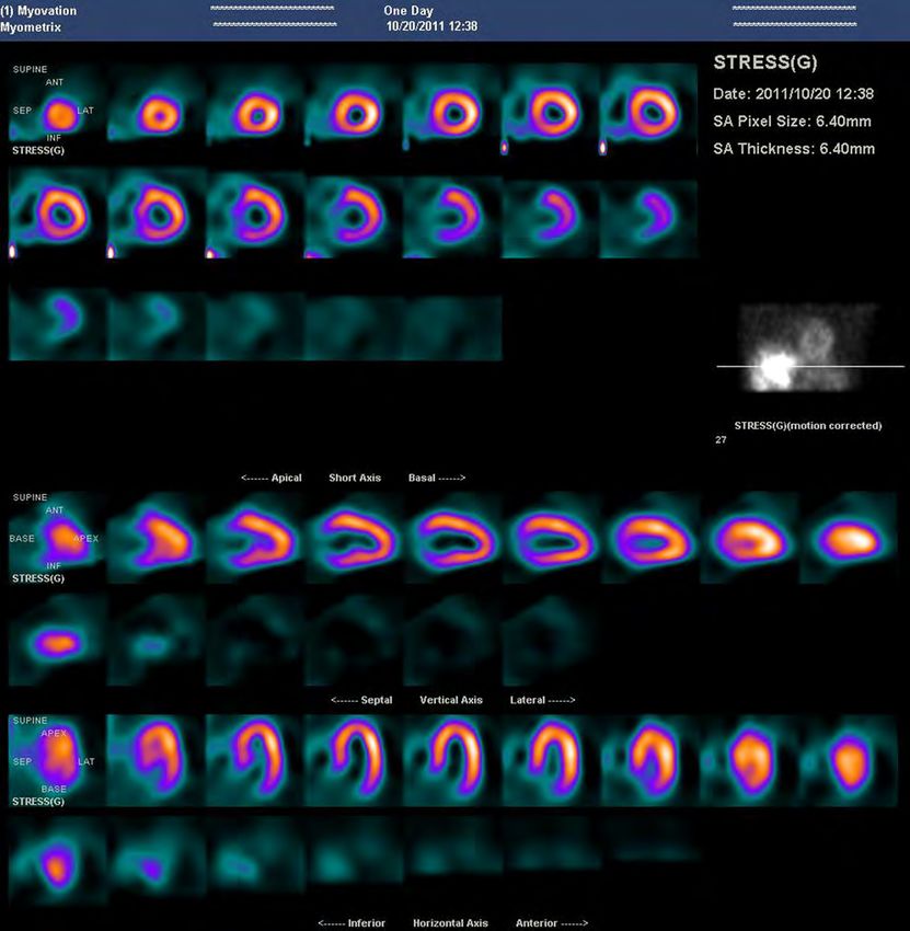
DePuey                                                                                           Journal of Nuclear Cardiology
      Advances in SPECT camera software and hardware

               Figure 8. Diagram of the IQ SPECTÒ variable-focus collimator, demonstrating magnification of
               the region of the myocardium and its immediate surroundings by means of converging collimation,
               while keeping the entire torso in the field-of-view by morphing the collimator holes to a near-
               parallel-hole geometry at the edges of the collimator. Spatial resolution increases with depth from
               the central area of the collimator surface.30 Courtesy Siemens Medical Solutions.

magnification and the point-response function of the               back of these detectors. Vertical collimation is achieved
collimator. Variable magnification results from the                using a unique curved lead sheet with six vertical slits
changing direction of each borehole with respect to                that rotates back-and-forth during acquisition to obtain
the collimator surface normal vector, while the point              data over the 180° imaging arc (Figure 9). The move-
response function depends on the finite size of the bore           ment of these six slits is synchronized electronically
holes. Therefore, an advanced reconstruction engine                with the six areas of the crystal that are imaging the
based on a conjugate-gradient algorithm with ordered               photons passing through the slits. Horizontal collimation
subsets that includes in the system matrix the view-angle          is accomplished by a series of thin lead sheets that are
dependent gantry deflections, a vector map of the col-             stacked vertically, with the gaps between the slits
limator hole angles, and the system’s point response               defining the hole apertures. By means of this ‘‘slit-hole’’
function, is used for cardiac SPECT reconstruction.                method, collimation is focused at the depth of the heart,
Based upon phantom experiments, as compared to a                   thereby increasing sensitivity and resolution. Counting
conventional low-energy high-resolution collimator, this           statistics comparable to those obtained with a conven-
novel cardio-focused collimator increases target sensi-            tional parallel-hole collimator in 21 minutes can be
tivity at 28 cm by a factor of C4 while maintaining                achieved in only approximately 5 minutes with the
comparable reconstructed resolution. The average reso-             CardiArcÒ scanner. The FWHM is 3.65 mm at a depth
lution (FWHM) is 6.97 mm in the x-plane and 6.91 mm                of 87 mm and 6.01 mm at 176 mm. To date, no clinical
in the y-plane.30 Therefore, with this novel collimator            validation of this system has been published.
scan times, patient dose, or a combination thereof may                  Multiple scanning parallel-hole collimators. The
be reduced by a factor of four while maintaining                   D-SPECTÒ camera, manufactured by Spectrum
acceptable spatial resolution.31                                   Dynamics incorporates nine pixilated cadmium zinc
     Arc detector geometry with rotating slit-hole                 telluride (CZT) crystal detector columns situated verti-
collimation. The CardiArcÒ scanner, dedicated to per-              cally, spanning an L-shaped 90° geometry (Figure 10).
forming myocardial perfusion SPECT scans,                          The patient is positioned semi-reclining, in a posture
manufactured by CardiArc Inc., uses a stationary curved            similar to that assumed a dentist’s chair. The L-shaped
camera head subtending a 180° angle, which is posi-                detector is positioned over the patient’s chest, centered
tioned centered over the patient’s precordium.6 The                over the left precordium. Each of the CZT detectors is
curved detector is composed of three adjacent curved               fitted with a square-hole tungsten collimator with an
sodium iodide crystals. Scintillation events are detected          inherent high transmission efficiency. The collimator
by an array of photomultiplier tubes mounted on the                holes are 21.7 mm in length and measure 2.26 mm on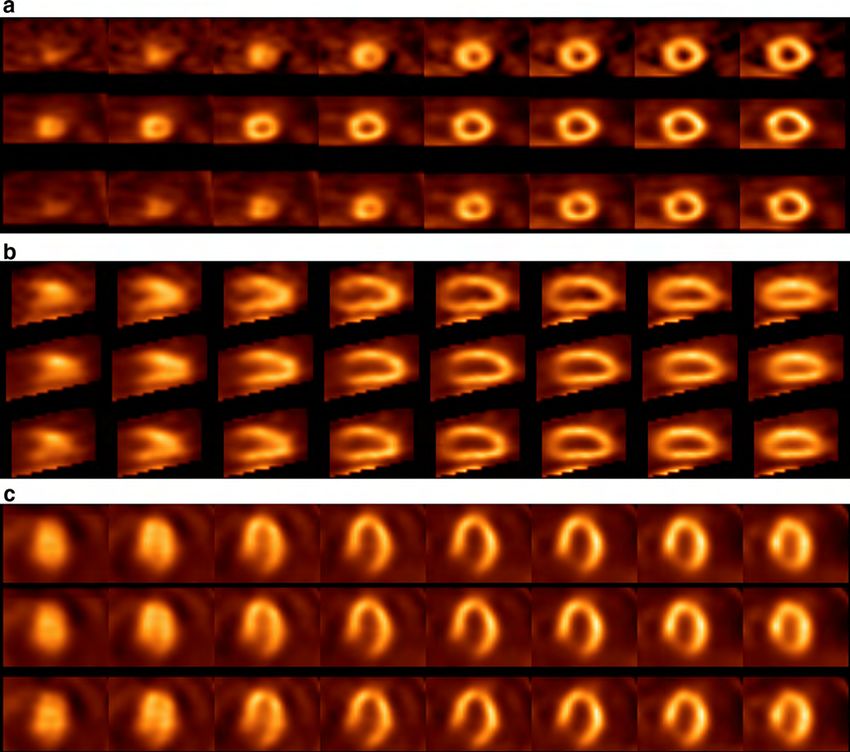
Journal of Nuclear Cardiology                                                                                         DePuey
                                                                               Advances in SPECT camera software and hardware

                                                                      each side of each square hole.32 These holes are shorter
                                                                      and wider than those used in conventional NaI detector
                                                                      low-energy, high-resolution collimators, which are typ-
                                                                      ically 45-mm long and 1.6-mm wide. Consequently, the
                                                                      solid angle for acceptance of incident photons for the
                                                                      D-SPECTÒ collimator is more than 8 times that of
                                                                      the standard low-energy high-resolution lead parallel-
                                                                      hole SPECT collimator.
                                                                           Emission data are first sampled by obtaining a
                                                                      15-second scout scan to allow the nine detectors to
                                                                      identify the location of the heart. Each collimated
                                                                      detector column rotates and translates independently a
                                                                      maximum of 110°, allowing voxels to be viewed from
                                                                      hundreds of different viewing angles. Data are acquired
                                                                      in list mode, allowing physiologic markers such as the
                                                                      electrocardiographic R wave, to be recorded simulta-
                                                                      neously. A sinogram is reconstructed and the location of
                                                                      the heart is derived, thereby setting the limits of the
                                                                      detectors’ fanning motion for a subsequent diagnostic
                                                                      scan. The diagnostic scan, typically a 4-minute acqui-
                                                                      sition, is performed with 120 projections/detector and
                                                                      2 seconds/projection. By this means for the diagnostic
                                                                      scan there is preferential sampling of photons emanating
                                                                      from the heart, whereby a greater proportion of imaging
                                                                      time is allocated to collecting data from the heart at the
                                                                      expense of collecting fewer data from less important
                                                                      surrounding and remote regions. Conceptually this
Figure 9. With the Cardiac ArcÒ Camera vertical collima-              design is equivalent to allowing pixels of a conventional
tion is achieved using a unique curved lead sheet with six            parallel collimator to acquire scintigraphic emissions
vertical slits that rotates back-and-forth during acquisition to      from the heart for a longer time than pixels acquiring
obtain data over the 180° imaging arc (A). Horizontal                 data from background structures.
collimation is accomplished by a series of thin lead sheets
that are stacked vertically (B). Courtesy Jack Juni, CardiArc              Although due to its unique L-shaped geometry, the
Inc.                                                                  D-SPECTÒ camera can be positioned very close to the

                 Figure 10. Schematic of the multiple scanning parallel-hole collimators of the D-SPECTÒ camera,
                 focused on the region of the heart following a pre-scan to determine the heart’s location. Courtesy,
                 Spectrum Dynamics.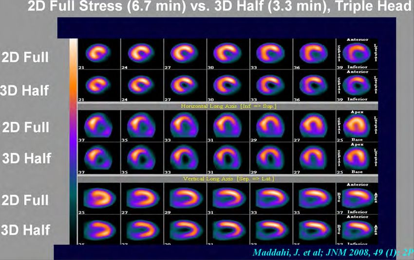
DePuey                                                                                         Journal of Nuclear Cardiology
       Advances in SPECT camera software and hardware

patient’s chest wall, clearly the wide, short, square-hole            long axis. Five are angled above, and five are angled
collimator design described above would result in much                below the axis, providing a 3-dimensional acquisition
poorer spatial resolution than that obtained using a con-             geometry. Each of the pinhole collimators simulta-
ventional SPECT camera equipped with a high-resolution                neously obtains an image of the heart, with no moving
parallel-hole collimator. The loss of spatial resolution is           parts during data acquisition. Because the distance
compensated for by the use of a proprietary BroadviewÒ                between the CZT detector and the pinhole is less than
software reconstruction algorithm based upon OSEM                     the distance between the pinhole and the heart, the
reconstruction, accurately modeling the probability                   cardiac image is minimized to preserve resolution, rather
function, supported by an increased number of viewing                 than maximized and distorted, as in the case of other
angles. Also, the reconstructed volume is fitted to a                 nuclear medicine pinhole applications such as pinhole
smooth ellipsoid-like surface, after which further itera-             imaging of the thyroid or the hips.
tions are performed, giving the myocardial walls a very                    Because the detectors and the patient are both sta-
thin appearance in typical D-SPECTÒ tomograms.32                      tionary, there are no ‘‘rotating’’ planar projection
     Multi-pinhole collimation. The General Electric                  images available to the interpreting physician to assess
Discovery NM 530cÒ camera employees 19 8 9 8 cm                       patient motion. Therefore, the location of the left breast
detectors focused on the heart to sample photons ema-                 and left hemidiaphragm as potential attenuators, and the
nating from the heart and the regions immediately                     location and intensity of subdiaphragmatic tracer con-
around it (Figure 11). Each detector contains 32 9 32                 centration as a potential cause of Compton scatter into
pixilated 5-mm thick CZT elements. The detector                       the inferior myocardial wall cannot be ascertained.
assembly is mounted on a gantry that allows for patient               However, a ‘‘scan QC’’ screen is provided that includes
positioning in either the supine or the prone position.               all pinhole views to aid the interpreting physician esti-
The size of the CZT modules allows the camera to be                   mate the location of these attenuators. With multi-
positioned closely enough to the chest wall to ensure                 pinhole collimation the focal point of the collimators is
that the detectors provide 3-D sampling of the heart                  within the thorax, so breast attenuation is less prob-
sufficient for tomographic reconstruction. The target                 lematical than with parallel-hole collimation. However,
volume is approximately a sphere of 19-cm diameter.                   the problems of diaphragmatic attenuation and subdia-
The patient is positioned so that the heart is centered               phragmatic Compton scatter are not avoided. Since high
within this field-of-view. Each of the 19 detectors is                counting statistics allow for dramatically reduced
composed of 4 solid-state CZT pixilated detectors                     SPECT acquisition times (see below), several laborato-
mounted by a single tungsten pinhole collimator with a                ries using the Discovery 530cÒ camera perform both
5.1 mm effective diameter aperture.33 Nine of the pin-                supine and prone SPECT routinely on all patients to
hole detectors are oriented perpendicular to the patient’s            better assess inferior myocardial tracer distribution.

                                                                      Solid-State Detectors
                                                                            Conventional sodium iodide scintillation cameras
                                                                      employ an array of photomultiplier tubes mounted
                                                                      behind the scintillation crystal. Typically photomulti-
                                                                      plier tubes are hexagonal or square and measure
                                                                      approximately 46 cm2. In general, there are over 50
                                                                      photomultiplier tubes in modern scintillation cameras.
                                                                      When a photon strikes the sodium iodide crystal, a flash
                                                                      of light is emitted, which is detected by all the
                                                                      photomultiplier tubes. Those tubes closest to the scin-
                                                                      tillation event receive more light than more distant
                                                                      tubes. Each photomultiplier tube is a photocathode,
                                                                      which emits electrons when impacted by light. By
                                                                      means of a cascading dynode array, the number of
                                                                      electrons is then multiplied, producing an electrical
                                                                      current output at the back end of the photomultiplier
Figure 11. Schematic of the multiple focused pinhole colli-
mator design of the Discovery NM 530cÒ camera, focused on
                                                                      tube. Those photomultiplier tubes closest to the scintil-
the region of the heart. Spatial resolution is optimal at the focal   lation event therefore produce a stronger electrical
depth of the collimators. Courtesy, General Electric Medical          signal than the more distant tubes. The location of the
Systems.                                                              scintillation event is then determined by electrical
Journal of Nuclear Cardiology DePuey
Advances in SPECT camera software and hardware
positioning circuitry, which combines the analog output
signals of all the photomultiplier tubes and computes a
weighted average of all the signals as a function of
position. This probabilistic method results in a Gaussian
spatial distribution, estimating the location of the scin-
tillation event.
As a result of this probabilistic approach, there is
considerable uncertainty in localization of the scintilla-
tion event, resulting in blurring of the scintigraphic
image and suboptimal spatial resolution. Also, the
positioning circuitry is relatively slow, limiting the
count-rate capabilities of conventional scintillation cam-
eras. To compound this shortcoming, the efficiency of
the photocathode of the photomultiplier tube in con-
verting optical photons to electrons only about 20%.
These combined factors result in relatively poor spatial
resolution and sensitivity of conventional scintillation
cameras.
In contrast, solid-state detectors are quantized, Figure 12. Schematic of the differences in spatial resolution
whereby the detector head is divided into an array of provided by a solid-state detector as compared to a conven-
tional NaI detector. With solid-state detectors the output is ‘‘all
individual detector elements. Crosstalk between these or none,’’ with resulting optimal spatial resolution. In contrast,
pixilated detectors is minimal; therefore, when a scin- using probabilistic positioning circuitry to process signals from
tigraphic event occurs each of the pixilated detectors an array of photomultiplier tubes, spatial resolution is poorer
produces an ‘‘all or none’’ output signal. The output is for NaI detectors, with blurring of object edges. Courtesy,
quantized and discrete rather than Gaussian, as in the Richard Conwell, Digirad Inc.
case of conventional sodium iodide cameras. Therefore,
the size and the spacing of the solid-state detector Direct solid-state detectors. In contrast to
elements define the spatial resolution of the detector indirect semiconductor detectors, CZT provides
(Figure 12). ‘‘direct’’ solid-state technology. The CZT semiconduc-
Indirect solid-state detectors. When gamma tor is a pixilated array approximately 5-mm thick with
rays are converted to electrical charge indirectly, first with an effective Z of 50 and a density of 5.8 g/cm3. Gamma
the gamma ray undergoing a scintillation event and being rays enter the CZT semiconductor detector and are
converted to light, then with the light converted to electron directly converted to electron hole pairs. These charges
hole pairs, the conversion process is termed ‘‘indirect.’’ (electrons and holes) then drift towards positive and
Indirect solid-state detectors are used in a wide variety of negative electrodes, respectively, producing electrical
medical imaging applications including CT scanners and output signals. Because not all the holes and the
PET cameras. The only scintillation specifically camera electrons drift towards the negative and the positive
designed for nuclear cardiology that employs indirect electrodes at the same rate, some of the holes get
solid-state technology is the Digirad camera. The scintil- delayed or ‘‘trapped’’ in the semiconductor material.
lator is cesium iodide (CsI), which has a good stopping This results in incomplete charge collection, in turn
power for low-energy gamma rays and emits more optical resulting in a broadening of the photopeak on the low-
photons than sodium iodide. Scintillation events are energy side. This ‘‘hole-tailing’’ effect varies from pixel
detected using a pixilated detector array.27 Each individ- to pixel within the array, but in general becomes more
ual detector element (pixel) measures 6 mm 9 6 mm 9 marked with increasing thicknesses of semiconductor
6 mm. These detectors are arranged in 24 modules, each material. For that reason, although CZT is more dense
containing two 4 9 4 arrays. Thus, each camera head is than sodium iodide (5.8 vs 3.7 gm/cm3), the thickness of
composed of an array of 768 6-mm detector elements. the CZT detector must be kept to a minimum (*5 mm).
Each CsI detector element is interfaced to a wafer-thin In this configuration, the CZT detector has excellent
(0.3 mm) silicon photodiode semiconductor detector. The energy resolution (FWHM = 5.4%, compared to a
silicon photodiode has a high efficiency in converting FWHM = 9.4% for a conventional sodium iodide cam-
optical photons to electrons. A bias voltage is applied era). With such improved energy resolution it is possible
across the semiconductor detector, resulting in electrical to clearly separate photons of Tc-99m (140 keV) and
output when the photodiode is impacted by optical iodine-123 (160 keV) (Figure 13). Similarly, the com-
photons created by a scintillation event. posite 70 keV photopeak and 81 keV lines of thallium-DePuey Journal of Nuclear Cardiology
Advances in SPECT camera software and hardware
201 are clearly resolved.34 However, due to the neces- with the spatial location of a fluorescent x-ray transmis-
sary thinness of the CZT detector, its intrinsic efficiency sion line source to form a fan-beam transmission
for detecting 140 keV gamma rays is only approxi- acquisition geometry. During the transmission scan the
mately equivalent to that of a conventional sodium chair on which the patient sits first rotates 206° for
iodide detector (88% vs 90%). Additionally, to over- 60 seconds with the transmission source on in order to
come the effects of the variation of hole-tailing per acquire the transmission data, then rotates 206° for
pixel, energy windows in CZT cameras are often set 60 seconds in the reverse direction with the transmission
relatively wide, as in conventional sodium iodide source off to acquire the contamination data from
cameras, to ±10%, making their scatter fraction perfor- emission sources in the patient to the transmission data.
mance similar to conventional sodium iodide cameras.35 The resulting attenuation map is of poor spatial resolu-
tion (relative to a diagnostic CT machine), but adequate
to correct the Tc-99m cardiac emission scan for soft
Attenuation Correction
tissue and blood pool attenuation. The associated patient
AC for myocardial perfusion SPECT has been radiation dose is only approximately 5 lSv. A limitation
available for over a decade, and therefore cannot truly of this method, shared by all other x-ray attenuation
be considered a ‘‘new advancement.’’ However, tech- techniques, is that the emission and subsequent trans-
nical advancements in AC now allow for reduced patient mission scans are sequential, allowing the possibility of
radiation dose associated with x-ray emission scans. patient motion between the emission and the transmis-
Diagnostic quality CT imaging of the chest is not sion scans and misregistration of the two. Due to the
necessary for AC. An attenuation map adequate for AC longer acquisition time for the low-flux fluorescent x-ray
can be generated using a lower mA and kVp. By this transmission scan, the opportunity for patient motion is
means state-of-the-art technology for AC of myocardial somewhat greater. Fortunately, however, software is
perfusion SPECT affords the patient only approximately available to easily register the emission and the trans-
0.2-0.4 mSv. mission scans.
A novel, ultra-low-dose AC method has been It should be emphasized that the increased count-
incorporated into the Digirad Cardius X-ACTÒ cam- rate statistics and improved image quality obtained with
era.27 After the emission scan has been acquired, the the new hardware methods described above are a result
camera’s three detectors are automatically reconfigured of combined advancements in both hardware and soft-
to form a single large 27-inch transaxial detector arc. ware. Spatial resolution for SPECT imaging of Tc-99m
The focal line of the collimator of each head co-aligns has been evaluated for the three new cameras described
above, all of which combine hardware and software
innovations. For the Digirad CardiusÒ detector head the
extrinsic planar resolution (FWHM) at 10 cm with
scatter was determined to be 9.9 mm with a LEHR
collimator and 10.6 mm with a LEAP collimator. Defect
contrast of the Data Spectrum phantom full defect was
0.528.27 For the Spectrum Dynamics D-SPECTÒ cam-
era, for a single line source the FWHM was
demonstrated to be 3.5 mm in the x-axis and 4.2 mm
in the y-axis, as compared to 9.2 and 12.5 mm, respec-
tively, for conventional SPECT.32 Compared to a
standard SPECT system, the D-SPECT camera was
demonstrated to have energy resolution *2 times better,
a point-source sensitivity *5 times higher, and a
superior count-rate capability.36 For the General Electric
Discovery NM 530cÒ camera SPECT resolution at
15 cm evaluated using three point sources with scatter
was determined to be 5.4 mm, compared to 9.4 mm for
conventional SPECT with a dual-head state-of-the-art
Figure 13. Pulse height spectra for Tc-99m and I-123 NaI detector.37 It should be emphasized that since these
obtained using a conventional NaI Anger camera and a CZT
solid-state detector (Alcyone, Discovery NM 530cÒ camera).
experiments evaluating system performance were per-
The two isotope peaks are discriminated much more effec- formed independently for each of the cameras, not
tively using the CZT detector. Courtesy, General Electric necessarily with settings used for clinical imaging, and
Medical Systems. since experimental parameters differed for each system,Journal of Nuclear Cardiology DePuey
Advances in SPECT camera software and hardware
it is not possible to draw direct comparisons. In fact, and resolution recovery, and ‘‘half-time’’ WBRÒ soft-
efforts to perform a more representative comparisons ware, incorporating these advancements as well as noise
show that the performance of these cameras are very compensation, were both equivalent or superior to gated
similar.38,39 Nevertheless, these innovative cameras, full-time FBP scans (Figures 14, 15). However, these
which combine advancements in detector characteris- authors observed that left ventricular functional param-
tics, collimation, and SPECT processing software, eters determined by both of these ‘‘half-time’’ methods
represent a tremendous advancement in the field of differed significantly from those derived from ‘‘full-
Nuclear Cardiology, enabling a significant decrease in time’’ FBP processing. LVEF’s averaged 3-9 points
image acquisition time, radiopharmaceutical dose, or lower with ‘‘half-time’’ processing compared to those
both. obtained using ‘‘full-time’’ FBP processing. Basso
et al40 reported similar results in a series of 47 patients.
Reduced-time WBRÒ yielded image quality superior to
CLINICAL RESULTS
that obtained with full-time FBP. In patients with
perfusion defects summed difference scores (SDSs)
Software Methods
were similar by both methods, but as reported by
In a single-center study of 50 patients, Borges-Neto DePuey et al, LVEFs were 9%-10% lower with the
et al15 reported similar myocardial perfusion SPECT WBRÒ method. In a prospective trial, Marcassa et al41
quality using WBRÒ (UltraSPECT, Ltd.) ‘‘half-time’’ studied 52 patients undergoing a rest/stress Tc-99m
software compared to standard ‘‘full-time’’ SPECT sestamibi protocol with ‘‘full-time’’ SPECT processed
acquisitions acquired on a standard dual-head sodium with FBP and ‘‘half-time’’ SPECT processed with
iodide detector and processed with FBP. Subsequently, WBRÒ. In addition, 40 other patients received half the
in a prospective series of 156 patients DePuey et al16 usual radiopharmaceutical dose and underwent ‘‘double-
reported that the image quality of gated perfusion time’’ SPECT processed with FBP and ‘‘full-time’’
SPECT obtained with both EvolutionÒ software (Gen- SPECT processed with WBRÒ. These investigators
eral Electric Medical Systems), incorporating OSEM reported that for either the ‘‘full-dose/half-time’’ or
Figure 14. Comparison of myocardial perfusion stress (A) and rest (B) SPECT acquired ‘‘full-
time’’ and processed with FBP (top row), compared to ‘‘half-time’’ SPECT processed with
EvolutionÒ software (bottom row), incorporating OSEM iterative reconstruction and resolution
recovery. A single-day rest/stress 9/32 mCi Tc-99m sestamibi protocol was used. Image quality and
resolution of the fixed anterior perfusion defect in this patient with a documented prior myocardial
infarction is equivalent using the ‘‘full-time’’ and ‘‘half-time’’ acquisition and processing
techniques. Courtesy Gordon DePuey, St. Luke’s-Roosevelt Hospital, New York, NY.DePuey Journal of Nuclear Cardiology Advances in SPECT camera software and hardware
Journal of Nuclear Cardiology                                                                                       DePuey
                                                                               Advances in SPECT camera software and hardware

b Figure 15. Comparison of myocardial perfusion stress SPECT           uniformity, endocardial/epicardial edge definition, and
  acquired ‘‘full-time’’ and processed with FBP (A), compared to       background noise. Perfusion defects were scored using a
  ‘‘half-time’’ SPECT processed with WBRÒ software, incorpo-
  rating OSEM iterative reconstruction, resolution recovery, and
                                                                       17-segment model. Using three commercially available
  noise compensation (B). A single-day rest/stress 9/32 mCi Tc-        software methods, EDV, ESV, and LVEF were calcu-
  99m sestamibi protocol was used. Image quality and resolution        lated. They demonstrated that by employing this more
  of the reversible inferior perfusion defect in this patient with a   rigorous noise compensation algorithm ‘‘quarter-time’’
  documented RCA stenosis is superior using the ‘‘half-time’’          perfusion SPECT afforded image quality, defect char-
  acquisition and processing techniques. Comparing gated post-
  stress SPECT image quality for the ‘‘full-time’’ (C) and ‘‘half-
                                                                       acterization, and functional assessment equivalent to
  time’’ (D) techniques, the former provided better image quality      full-time OSEM, providing the potential for even more
  with superior definition of the endocardial borders. Courtesy        markedly decreased SPECT acquisition times and/or
  Gordon DePuey, St. Luke’s-Roosevelt Hospital, New York, NY.          radiopharmaceutical doses. However, just as described
                                                                       above for WBRÒ ‘‘half-time’’ processing, these authors
                                                                       observed that left ventricular functional parameters
  ‘‘half-dose/full-time’’ WBRÒ methods image quality                   determined by ‘‘quarter-time’’ WBRÒ averaged 3-9
  and defect characteristics (SSSs) did not differ signif-             points lower than those obtained using ‘‘full-time’’
  icantly from standard acquisition and FBP processing                 OSEM processing. They postulated that the lower
  methods.                                                             LVEFs obtained with ‘‘quarter-time’’ WBRÒ resulted
       In a prospective study reported by Druz et al,42 434            from more accurate tracking of the motion of the left
  patients underwent ‘‘full-time’’ (20 second/stop) dual-              ventricular valve plane during ventricular systole, and
  isotope Tl-201/Tc-99m sestamibi SPECT processed                      therefore seemed to better correspond to visual estima-
  with FBP, followed by half-time (10 second/stop)                     tion of LVEF. Consequently, they recommended that
  SPECT processed with WBRÒ. For experienced nuclear                   when following an individual patient, the same acqui-
  cardiologist interpreting the scans diagnostic certainty             sition and processing methods should be used to
  was better for the ‘‘half-time’’ WBRÒ scans. The                     determine functional parameters. Ideally, normal dat-
  percentage of ‘‘equivocal’’ interpretations decreased                abases should be determined for each commercially
  from 35 to 9 (P \ .0001). In a subgroup of patients who              available method used to determine left ventricular
  underwent coronary angiography, there were no differ-                functional parameters.
  ences in diagnostic sensitivity, specificity, or accuracy                 Subsequently, using ‘‘half-time’’ WBRÒ software,
  between the two methods.                                             DePuey et al46 studied 156 consecutive patients in
       Using AstonishÒ software developed by Phillips,                 whom rest and 8-frame gated post-stress myocardial
  incorporating resolution recovery and a different                    perfusion SPECT were performed following 9-12 mCi
  reduced-time software processing method, in a series                 and 32-40 mCi Tc-99m sestamibi injections, respec-
  of 221 patients in whom ‘‘half-time’’ acquisitions were              tively,       with      full-time     (rest = 14 minutes;
  simulated by dropping every other frame/stop of data                 stress = 12.3 minute) acquisitions processed with
  during a 180° SPECT acquisition, Venero et al observed               OSEM, and also separate ‘‘half-time’’ acquisitions
  myocardial perfusion defect characteristics to be nearly             processed with WBRÒ. A separate group of 160 con-
  identical to the ‘‘full-time’’ and simulated ‘‘half-time’’           secutive patients matched in gender, weight, and chest
  techniques. Left ventricular functional parameters cor-              circumference received ‘‘half-dose’’ rest and stress
  related well using the standard and reduced-time                     injections (5.8 ± 0.6 and 17.5 ± 2.5 mCi) with full-time
  methods43 (Figure 16). ‘‘Half-time’’ SPECT simulated                 SPECT acquisitions. Image quality was again scored
  with this ‘‘data stripping’’ method combined with Gd-                based upon myocardial count density and uniformity,
  153 line-source AC has also been reported to improve                 endocardial edge definition, perfusion defect delinea-
  diagnostic certainty as compared to non-attenuation-                 tion, right ventricular visualization, and background
  corrected simulated ‘‘half-time‘‘ SPECT.44                           noise. ‘‘Half-time’’ and ‘‘half-dose’’ WBRÒ non-gated
       In a later report, DePuey et al45 imaged 209 patients           and gated image quality were both superior to standard
  prospectively at rest and following exercise or pharma-              full-time OSEM (P’s \ .001). Mean image quality for
  cologic stress (9/32 mCi 99mTc-sestamibi) full-time                  rest, stress, and post-stress gated images were similarly
  processed with OSEM, and again ‘‘quarter-time’’ pro-                 excellent for ‘‘half-time’’ and ‘‘half-dose’’ WBRÒ
  cessed with a modified WBRÒ algorithm (Xpress-3Ò,                    (Figure 18). There was no significant difference between
  UltraSPECT, Ltd.), incorporating a noise compensation                the summed stress and the rest scores for ‘‘full-time’’
  technique more rigorous than the one employed for the                OSEM versus ‘‘half-time’’ WBRÒ in 82 patients with
  previously described ‘‘half-time’’ technique (Fig-                   perfusion defects. Therefore, these authors concluded
  ure 17). Blinded observers graded scan quality                       that software methods that cope with reduced myocar-
  (1 = poor to 5 = excellent) based on myocardial                      dial perfusion SPECT count density can be applied
You can also read


