Simulations of mode-selective photonic lanterns for efficient coupling of starlight into the single-mode regime
←
→
Page content transcription
If your browser does not render page correctly, please read the page content below
Research Article                                                                                                            Applied Optics   1

                                               Simulations of mode-selective photonic lanterns for
                                               efficient coupling of starlight into the single-mode
                                               regime
                                               M OMEN D IAB1,* , A ASHANA T RIPATHI1 , J OHN DAVENPORT1 , A LINE N. D INKELAKER1 , K ALAGA
arXiv:2103.14047v1 [astro-ph.IM] 25 Mar 2021

                                               M ADHAV1 , AND M ARTIN M. R OTH1
                                               1 innoFSPEC,   Leibniz Institute for Astrophysics Potsdam, An der Sternwarte, D-14482 Potsdam, Germany
                                               * Corresponding  author: mdiab@aip.de

                                               Compiled March 29, 2021

                                                     In ground-based astronomy, starlight distorted by the atmosphere couples poorly into single-mode waveg-
                                                     uides but a correction by adaptive optics, even if only partial, can boost coupling into the few-mode
                                                     regime allowing the use of photonic lanterns to convert into multiple single-mode beams. Corrected
                                                     wavefronts result in focal patterns that couple mostly with the circularly symmetric waveguide modes.
                                                     A mode-selective photonic lantern is hence proposed to convert the multimode light into a subset of the
                                                     single-mode waveguides of the standard photonic lantern, thereby reducing the required number of out-
                                                     puts. We ran simulations to show that only two out of the six waveguides of a 1 × 6 photonic lantern carry
                                                     > 95% of the coupled light to the outputs at D/r0 < 10 if the wavefront is partially corrected and the
                                                     photonic lantern is made mode-selective. © 2021 Optical Society of America
                                                     http://doi.org/10.1364/AO.421799

                                               1. INTRODUCTION                                                                photonic device [2].
                                                                                                                                  Partially AO-corrected wavefronts result in PSFs that have
                                               Although starlight arrives at the top of Earth’s atmosphere with               a prominent core on top of a background halo [3]. The near
                                               planar wavefronts that would form Airy patterns when focused                   symmetry of such PSFs means that they have a stronger overlap
                                               by unobscured circular apertures, atmospheric turbulence dis-                  with the circularly symmetric modes of the linearly polarized
                                               torts the wavefronts before they are collected by ground-based                 (LP) modes of step-index circular fibers. By breaking the degen-
                                               telescopes. Such distortion introduce random information into                  eracy between the single-mode waveguides, a mode-selective
                                               the wavefront which translates into the point spread function                  photonic lantern (MSPL) like the one depicted in Fig. 1 can be
                                               (PSF) breaking up into a speckle pattern that couples poorly                   designed that converts the light coupled into a certain spatial
                                               with single-mode waveguides. Photonic lanterns can be used to                  mode to one specific output waveguide [4]. For the case of par-
                                               couple atmospherically-distorted starlight into single-mode in-                tially AO-corrected PSFs, this can be exploited to transform most
                                               tegrated optics and fibers, where the multimode speckle pattern                of the coupled multimode starlight into a subset of the total num-
                                               at the focal plane is converted into multiple single-mode beams.               ber of modes supported by the photonic lantern. Specifically,
                                               This conversion is however only lossless if the degrees of free-               most of the light can be coupled into the waveguides associated
                                               dom are conserved, i.e. the number of single-mode channels is at               with the circularly symmetric modes (LP0m , m = 1, 2, ...) and
                                               least equal to the number of supported modes at the multimode                  thus reduce the number of single-mode channels, i.e. waveg-
                                               input [1]. Since the modal content of the seeing-limited PSF                   uides, that needs to be handled at the output of the photonic
                                               increases as the telescope aperture grows or as seeing worsens,                lantern without significant loss of light.
                                               hundreds, if not thousands, of modes are required to efficiently                   While conventional photonic lanterns were originally in-
                                               couple all the starlight into the multimode port of the lantern                vented to accommodate fiber Bragg grating-based sky emission
                                               which results in the signal getting split among an equal number                filters for H-band astronomy [5], MSPLs were first used as spatial
                                               of single-mode channels. To minimize the size of the lantern,                  division multiplexers (SDMs) to increase the capacity of optical
                                               adaptive optics (AO) may be used to first correct the received                 communication channels [4]. They have since been proposed
                                               wavefront and hence reduce the modal content of the PSF to the                 to multiplex orbital angular momentum modes [6] and to selec-
                                               point where only ∼ 10s of modes are required to efficiently cou-               tively amplify spatial modes in doped fibers [7]. MSPLs also
                                               ple the PSF of a ground-based large telescope into a multiplexed               found applications as bending sensors [8], as differential group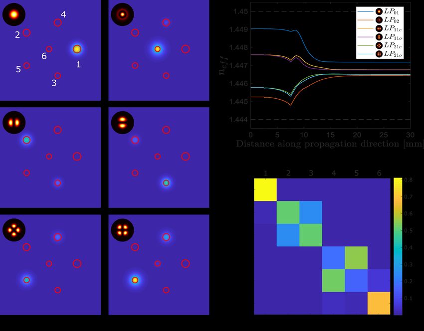
Research Article                                                                                                           Applied Optics   2

                                                                      block of GLS or Eagle glass [20] with refractive index contrast
                                                                      ∆ = (ncore − ncladding )/ncore = 4.138 × 10⁻³ [21].
                                                                          To avoid mode coupling along the transition, the adiabaticity
                                                                      criterion [22, 23]
                                                                                           2π dρ
                                                                                                       Z
                                                                                                                    ∂ψ2
                                                                                                               ψ1       dA  1,              (1)
                                                                                        β 1 − β 2 dz       A         ∂ρ
                                                                      must be fulfilled. The criterion demands that the propagation
                                                                      constants β 1 and β 2 of neighboring modes ψ1 and ψ2 that evolve
                                                                      slowly along the taper to be well separated if the taper length
                                                                      is to remain short enough for the simulations to conclude in a
                                                                      reasonable time. In Eq. 1, ρ is the local core size and z is the
                                                                      longitudinal coordinate, making dρ/dz a measure of the taper
                                                                      ratio, while A is the structure cross-sectional area. The range
                                                                      of propagation constants to be filled ( β max − β min ) is limited by
                                                                      the wavelength and the normalized frequency (V-number) of
Fig. 1. Layout of a 1 × 6 MSPL inscribed in a glass substrate.        the single-mode waveguides. It has an upper limit determined
Corrected starlight coupled into the few-mode core (grey) will        by the requirement for the largest waveguide in the array (cor-
predominantly route towards the two single-mode cores (blue)          responding to the fundamental mode of the multimode core)
that correspond to the LP0m modes of the input.                       to remain single-mode and the smallest (corresponding to the
                                                                      highest order mode of the multimode core) to be 3.6 times larger
                                                                      than the longest operating wavelength to have a V-number of at
delay compensator [9] and made a comeback to astronomy as a           least 1.5 for good field confinement of the field within the core.
way of mitigating focal ratio degradation [10].                       The minimum separation to have the output waveguides decou-
   In this work, we present simulation results that demonstrate       pled is ∼ 30 µm. With a device length of 50 mm, the taper angle
the potential of MSPLs as a method of reducing the number             is 0.03°and therefore the taper is gradual enough to guarantee
of single-mode channels for the various astronomical appli-           adiabaticity.
cations that photonic lanterns have been suggested for so far,            In addition to the bounds set by the propagation constants
e.g. OH suppression [5], reformatting [11], multiplexed spec-         range, the maximum diameter for the single-mode cores and
trographs [12], and beam combiners [13, 14]. First, the working       the minimum diameter for the multimode core depend on the
principle and the design of the MSPL we considered are given.         operating wavelength range. The diameters are chosen such that
Next, we show how the modal content of starlight PSFs de-             the device will operate across the H-band (1550 - 1800 nm) while
pends on the turbulence strength and the degree of correction.        keeping the number of supported modes at both ends the same.
We finally present the expected performance results of using a            Two MSPLs were designed within the constraints given
1 × 6 and a 1 × 15 MSPLs to convert AO corrected PSFs into few        above, a 1 × 6 and a 1 × 15. The anatomy of both devices con-
single-mode beams and discuss the limits beyond which this            sists of three segments. The input at the front facet of the glass
approach becomes less beneficial.                                     substrate is a straight, uniform, few-mode core that can be read-
                                                                      ily spliced to a fiber. The tapered cores start at the end of the
                                                                      few-mode core with a matching diameter and then taper over a 5
2. CONCEPT AND MSPL DESIGN
                                                                      mm length down to the designated final diameter while fanning
Conventional photonic lanterns guide the light from a multi-          out from the center to form a pentagon with a central core for
mode core through an adiabatic transition to an array of iden-        the 1 × 6 MSPL. The 1 × 15 MSPL has the remaining 9 cores
tical single-mode cores [15]. A one-to-one mapping between            fanning into an outer nonagon and thus meeting the geometric
the spatial modes of the multimode end and the single-mode            requirement for lossless transition [17]. The last segment has
waveguides of the array can be achieved with an MSPL that             cores of uniform diameters that continue to fan out at the same
has dissimilar diameters or refractive indices for the array cores.   angle for 22 mm to a maximum separation of 30 µm from the
The fundamental modes supported by the single-mode waveg-             center where the cores are decoupled. These segments can be
uides will consequently have different propagation constants          identified by the jumps in the effective refractive index curves
leading to the modes of the input port orderly coupling with          in Fig. 2(b).
the dissimilar cores one by one. Single-mode waveguides sup-              For the 1 × 6 MSPL (cf. Fig. 1), the multimode core has a
port only the fundamental mode LP01 . Higher-order circularly         diameter of 18.58 µm and NA = 0.13177 and therefore supports
symmetric modes, LP02 and LP03 , are supported by 6 and 15            the 6 modes (12 vector modes): LP01 , 2 × LP11 , 2 × LP21 , and
modes waveguides, respectively. Disregarding geometry, one            LP02 between λ = 1550 and 1800 nm. The diameters for the
could directly assign different diameters or refractive indices to    6 single-mode waveguides found by the optimization are 8.5,
the cores in descending order within the allowed range. The           7.5, 7.5, 5.8, 5.8, and 5.6 µm, respectively. While the MSPL is
modes from the multimode core would then occupy the single-           highly selective for all modes, only the waveguides for LP0m
mode cores in succession. Opting for dissimilar core sizes rather     modes are of interest here. Figure 2(a) shows the light spatial
than varying the refractive indices and since the selectivity of      distribution corresponding to excitations with pure modes and
the device can be improved by optimizing the diameters to the         Fig. 2(c) shows the selectivity matrix of the device, where the
cores arrangement [16, 17], we carried out an optimization of the     rows indicate how much of the total power launched into a
geometry parameters using the beam propagation solver Beam-           given mode ends up at each core.
PROP [18] on CAD models of the structures. The designs assume             A similar procedure is followed for the 1 × 15 MSPL except
a device written using ultrafast laser inscription (ULI) [19] in a    that the diameters for the waveguides associated with the de-
Research Article Applied Optics 3
Fig. 2. (a) Output patterns of the 1 × 6 MSPL due to excitations by a pure mode. The insets show the launched mode. (b) Variation
of the effective index along the propagation direction. Horizontal dashed lines indicate the cladding and the core refractive indices
and the vertical dotted lines indicate the interfaces between the segments of the device. (c) Selectivity matrix illustrating the power
shares of the output cores with a pure mode launched.
generate higher-order modes (LP1m , LP2m , ...) are all set to the into single-mode fibers a 100-fold and decrease the number of
same value to narrow the parameter space of the optimization, channels required of the photonic lanterns for full coupling to
as only LP01 , LP02 and LP03 are relevant for this application. only ∼ 10s [2].
Through scrambling, AO-assisted photonic lanterns can re-
3. STARLIGHT COUPLING INTO FEW-MODE WAVEG- distribute the light, more or less, equally among the single-mode
UIDES channels [25] and therefore one would need to process the beams
at all output ports if the flux collected by the telescope is to be
The atmospherically induced distortion of starlight, particularly
fully utilized. Without scrambling, the redistribution is not equal
in the field’s phase, precludes efficient coupling into single-mode
but rather highly dependent on the time-varying environmental
photonic devices, but a combination of AO and photonic lanterns
and atmospheric conditions, meaning again that all the channels
can help couple light efficiently into astrophotonic instruments
must be used. An MSPL can help reduce the number of channels
that allow multiplexing. Without any correction, the number of
by routing most of the light coupled into the multimode core to
modes that the photonic lantern would need to support, p, (and
only 2 of the total 6 channels of a 1 × 6 MSPL.
in turn the number of channels of the device) depends on the
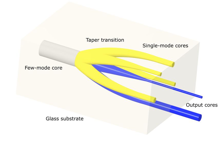
Figure 3 shows the contribution of each mode to coupling
aperture of the telescope, D, and the seeing condition gauged
into a 6 modes waveguide as the turbulence strength D/r0 is
by Fried’s parameter r0 [24]:
increased for both, the uncorrected and the AO-corrected cases.
π 2 D2 For this computation, 20 seeing-limited PSFs, ψE , at each D/r0
p≈ . (2)
4r02 point are calculated from Kolmogorov’s phase screens [26] and
the overlap with the LP modes of a weakly-guiding, step-index
A 4 m telescope at median seeing conditions, r0 = 20 cm, in circular waveguide, ψi , is evaluated to find the coupling contri-
the NIR would require ∼ 1000 channels to couple the light effi- butions ηi
ciently into a multiplexed single-mode integrated optic. To fully
correct such a wavefront, an AO system that has a comparable |hψi |ψE i|2
∼ 1000 degrees of freedom, i.e. count of the wavefront sensor ηi = . (3)
hψi |ψi i hψE |ψE i
(WFS) subapertures and the deformable mirror (DM) actuators,
is required. However, a partial correction with only a ∼ 100 actu- To compute the LP modes analytically, an ansatz that sat-
ators low-order system can already boost the coupling efficiency isfies the symmetry boundary conditions of the cylindrical,Research Article Applied Optics 4
Fig. 3. Contribution of the modes to coupling from an unobscured circular aperture at the optimum f /# = 4.83 at λ = 1550 nm as
D/r0 is increased for a six-mode waveguide. Left: Without AO correction. Right: with partial AO correction.
Fig. 4. Normalized optical power at the single-mode output cores as turbulence strength increases for unobscured circular aper-
tures. Insets show the cores arrangement at the output. Top: 1 × 6 MSPL. Bottom: 1 × 15 MSPL. Left: No correction. Right: With AO
correction
step-index waveguide is substituted in the Helmholtz equation, simulating a Shack-Hartmann WFS and a DM that has 97 actua-
∇2 ψ + n2 k20 ψ = 0 [22]. The resulting differential equations have tors [27]. A modal reconstruction is performed to calculate the
solutions in the family of Bessel functions. Imposing the weak wavefront from the local slopes sensed by the WFS and find the
guidance condition, ∆
1, a characteristic equation is obtained commands for the DM [3].
that may be solved graphically to determine the parameters of
the modes and subsequently their spatial distribution. For the uncorrected case, the contributions of LP01 and LP02
are initially highest, but drop for increasing turbulence, with
AO correction is applied to the distorted phase screens by higher-order modes quickly contributing similar amounts. InResearch Article Applied Optics 5
ratio is improved by requiring the stacking of fewer signals in
post-processing after detection [2]. The MSPL is selective across
the H-band where the modal count of both ports remains the
same.
Several methods can be considered to fabricate MSPLs. For
the simulations presented here, we have assumed the ULI tech-
nique. With ULI, 3D structures can be written into bulk glass
by moving the substrate in all three dimensions relative to a
focused short-pulse laser beam. The refractive index is modified
at the focus, thereby producing waveguide structures. By com-
bining laser parameters, focusing optics, and sample movement
Fig. 5. Share of light contained in the two LP0m cores for appropriately, the position, shape, and size of each waveguide
the 1 × 6 MSPL. Curves are shown for obscuration ratio can be changed. ULI has already been used to write single-
= 0%, 12.5%, 20%, and 50%. mode waveguides, directional couplers and interferometers [29],
Bragg-gratings [30], photonic reformatters [31, 32], as well as
photonic lanterns [19, 20]. MSPLs, however, have not yet been
fabricated using ULI. High positional precision and repeatabil-
the case where partial AO correction is applied on the distorted
ity will be required to shape the individual waveguides, espe-
wavefronts, contributing the most are the LP01 and LP02 modes.
cially for the lowest mode field diameter (MFD) difference of
The same calculation was performed for the 1 × 15 MSPL, where
200 nm between mode-selective waveguides in our simulations.
we still find LP01 and LP02 carry the largest fraction of light.
Here, the substrate motion will be crucial. For systems utilizing
LP03 , however, does not contribute.
air-bearing translation stages, (e.g. [30, 32]), hardware specifi-
cations from the manufacturers state positioning repeatability
4. STARLIGHT COUPLING INTO MSPLS of ±25 − 100 nm. While we expect the precision to be suffi-
To demonstrate the MSPL ability to convert the multimode cient, experimental tests should be conducted to verify MFD
starlight to a few of its single-mode outputs, focal fields of AO- and selective coupling of ULI-manufactured devices. The ef-
corrected wavefronts at the optimum coupling f /# are com- fect of position uncertainty might be mitigated when using the
puted and launched into the multimode waveguide of a model multiscan technique, where the combined index change of sev-
of a 1 × 6 MSPL. The beam propagation method is then used to eral displaced scans accumulates to form the final waveguide,
evolve the launch field along the MSPL and calculate the output e.g. [30].
fields at the tips of the single-mode waveguides. Figure 4 shows Furthermore, photonic lanterns can be produced by tapering
the dependence of the power at the outputs on D/r0 for the stacks of optical fibers. Many single-mode fibers fuse together
corrected and the uncorrected cases at λ = 1550 nm. to form the multi-mode waveguide [11]. MSPLs can be pro-
As the overlap of the corrected PSF with the LP01 mode is duced by this method, either by using optical fibers of varying
higher than the overlap with LP02 , the 1 × 6 MSPL will always sizes [23], with similar cladding diameters but different cores [4],
redistribute the light unequally between the two output waveg- or using a multicore fiber [10].
uides. Without further scrambling, this may prove problem- With a fabricated device, the simulation results reported here
atic for certain applications, e.g. high-resolution spectroscopy, can be verified on an AO testbed where D/r0 , the degree of
and would require a redistribution among the channels using a correction, and the obscuration ratio can be changed [33]. Af-
scrambling device for the outputs. ter initial proof-of-concept experiments in the lab, subsequent
Of the total optical power coupled from free space into the on-sky tests would be required. As losses in the laser-written
1 × 6 MSPL, > 99% is delivered to the two cores associated with devices can accumulate to cancel any signal advantage from the
LP0m at the diffraction limit. The preference for the light to steer MSPL, the throughput has to be evaluated. Optimization might
toward those cores decreases as turbulence strength is increased be required to reduce losses. However, if the throughput is too
but the share of the power remains > 85% at all D/r0 < 20 for low, a similar MSPL could be fabricated from a fiber stack for
the unobscured telescope. Figure 5 shows how the share of the testing on an astronomical telescope. Both techniques can be
power in the two LP0m cores of a 1 × 6 MSPL depends on D/ro used complementally to find suitable MSPL configurations for
and the obscuration ratio of the telescope. At the diffraction different telescopes and AO systems in order to improve light
limit, a central obscuration effectively redistributes part of the coupling in photonic devices under the effect of turbulence.
power from the Airy disk into the rings and thus increases the
coupling into the higher-order LP0m modes. The total share of
Funding. German Federal Ministry of Education and Research
the power remains the same in these circularly symmetric modes (BMBF) (03Z22AN11).
as seen in Fig. 5.
Acknowledgments. The authors thank the Photonic Instrumenta-
5. CONCLUSION AND FUTURE OUTLOOK tion (PHI) Group at Heriot-Watt University, especially Aurélien Benoit,
We have run simulations to demonstrate the potential of MSPLs for fruitful discussions on the ULI technique.
to coupling starlight into the single-mode regime upon intro-
ducing AO correction to atmospherically distorted wavefronts. Disclosures. The authors declare no conflicts of interest.
MSPLs can reduce the number of output beams that one needs
to consider as compared to conventional photonic lanterns for Data Availability. Data underlying the results presented in this
an equal total flux delivered. For multiplexed photonic de- paper are not publicly available at this time but may be obtained from
vices [28], fewer channels also mean that the signal-to-noise the authors upon reasonable request.Research Article Applied Optics 6
REFERENCES Optical Society of America.
17. N. K. Fontaine, R. Ryf, J. Bland-Hawthorn, and S. G. Leon-Saval, “Geo-
1. S. G. Leon-Saval, T. A. Birks, J. Bland-Hawthorn, and M. Englund,
metric requirements for photonic lanterns in space division multiplexing,”
“Multimode fiber devices with single-mode performance,” Opt. Lett. 30,
Opt. Express 20, 27123 (2012).
2545 (2005).
18. Synposys and RSoft Design Group, RSoft, CAD & BeamPROP, Syn-
2. M. Diab, A. N. Dinkelaker, J. Davenport, K. Madhav, and M. M. Roth,
opsys Inc, CA, USA (1993-2018).
“Starlight coupling through atmospheric turbulence into few-mode fi-
19. R. R. Thomson, T. A. Birks, S. G. Leon-Saval, A. K. Kar, and J. Bland-
bres and photonic lanterns in the presence of partial adaptive optics
Hawthorn, “Ultrafast laser inscription of an integrated photonic lantern,”
correction,” Mon. Notices Royal Astron. Soc. 501, 1557–1567 (2021).
Opt. Express 19, 5698–5705 (2011). Publisher: Optical Society of
3. J. W. Hardy, Adaptive Optics for Astronomical Telescopes (Oxford
America.
Series in Optical & Ima, New York, 1998), new edition ed.
20. I. Spaleniak, N. Jovanovic, S. Gross, M. J. Ireland, J. S. Lawrence, and
4. S. G. Leon-Saval, N. K. Fontaine, J. R. Salazar-Gil, B. Ercan, R. Ryf,
M. J. Withford, “Integrated photonic building blocks for next-generation
and J. Bland-Hawthorn, “Mode-selective photonic lanterns for space-
astronomical instrumentation II: the multimode to single mode transi-
division multiplexing,” Opt. Express 22, 1036–1044 (2014). Publisher:
tion,” Opt. Express 21, 27197 (2013).
Optical Society of America.
21. J. Tepper, L. Labadie, R. Diener, S. Minardi, J.-U. Pott, R. Thomson,
5. J. Bland-Hawthorn, S. C. Ellis, S. G. Leon-Saval, R. Haynes, M. M.
and S. Nolte, “Integrated optics prototype beam combiner for long
Roth, H.-G. Löhmannsröben, A. J. Horton, J.-G. Cuby, T. A. Birks,
baseline interferometry in the L and M bands,” Astron. & Astrophys.
J. S. Lawrence, P. Gillingham, S. D. Ryder, and C. Trinh, “A complex
602, A66 (2017). Publisher: EDP Sciences.
multi-notch astronomical filter to suppress the bright infrared sky,” Nat.
22. A. W. Snyder and J. Love, Optical Waveguide Theory (Springer Science
Commun. 2, 581 (2011). Number: 1 Publisher: Nature Publishing
& Business Media, 2012). Google-Books-ID: DCXVBwAAQBAJ.
Group.
23. S. Yerolatsitis, I. Gris-Sánchez, and T. A. Birks, “Adiabatically-tapered
6. X. Zeng, Y. Li, L. Feng, S. Wu, C. Yang, W. Li, W. Tong, and J. Wu,
fiber mode multiplexers,” Opt. Express 22, 608–617 (2014). Publisher:
“All-fiber orbital angular momentum mode multiplexer based on a mode-
Optical Society of America.
selective photonic lantern and a mode polarization controller,” Opt. Lett.
24. S. Minardi, R. Harris, and L. Labadie, “Astrophotonics: astron-
43, 4779–4782 (2018). Publisher: Optical Society of America.
omy and modern optics,” arXiv:2003.12485 [astro-ph] (2020). ArXiv:
7. S. Wittek, R. B. Ramirez, J. A. Zacarias, Z. S. Eznaveh, J. Bradford,
2003.12485.
G. L. Galmiche, D. Zhang, W. Zhu, J. Antonio-Lopez, L. Shah, and
25. J. Baudrand and G. Walker, “Modal Noise in High-Resolution, Fiber-fed
R. A. Correa, “Mode-selective amplification in a large mode area Yb-
Spectra: A Study and Simple Cure,” Publ. Astron. Soc. Pac. 113, 851–
doped fiber using a photonic lantern,” Opt. Lett. 41, 2157–2160 (2016).
858 (2001). Publisher: [The University of Chicago Press, Astronomical
Publisher: Optical Society of America.
Society of the Pacific].
8. A. V. Newkirk, J. E. Antonio-Lopez, A. Velazquez-Benitez, J. Albert,
26. B. M. Welsh, “A Fourier series based atmospheric phase screen gen-
R. Amezcua-Correa, and A. Schülzgen, “Bending sensor combining
erator for simulating anisoplanatic geometries and temporal evolution,”
multicore fiber with a mode-selective photonic lantern,” Opt. Lett. 40,
in Proc. SPIE, vol. 3125 (1997), pp. 327–338.
5188–5191 (2015). Publisher: Optical Society of America.
27. K. V. Gorkom, K. L. Miller, J. R. Males, O. Guyon, A. T. Rodack, J. Lum-
9. B. Huang, N. K. Fontaine, R. Ryf, B. Guan, S. G. Leon-Saval,
bres, and J. M. Knight, “Characterization of deformable mirrors for the
R. Shubochkin, Y. Sun, R. Lingle, and G. Li, “All-fiber mode-group-
MagAO-X project,” in Adaptive Optics Systems VI, vol. 10703 (Interna-
selective photonic lantern using graded-index multimode fibers,” Opt.
tional Society for Optics and Photonics, 2018), p. 107035A.
Express 23, 224–234 (2015). Publisher: Optical Society of America.
28. F. G. Watson, “Multifiber waveguide spectrograph for astronomy,” in
10. A. Benoit, S. Yerolatsitis, K. Harrington, T. A. Birks, and R. R. Thom-
Fiber Optics in Astronomical Applications, vol. 2476 (International
son, “A focal-ratio-degradation resistant multimode fiber link using
Society for Optics and Photonics, 1995), pp. 68–74.
mode-selective photonic lantern,” in Advances in Optical and Mechan-
29. S. Piacentini, T. Vogl, G. Corrielli, P. K. Lam, and R. Osellame,
ical Technologies for Telescopes and Instrumentation IV, vol. 11451
“Space Qualification of Ultrafast Laser-Written Integrated Waveg-
R. Navarro and R. Geyl, eds. (SPIE, 2020), pp. 408 – 413. Backup
uide Optics,” Laser & Photonics Rev. n/a, 2000167 (2020). _eprint:
Publisher: International Society for Optics and Photonics.
https://onlinelibrary.wiley.com/doi/pdf/10.1002/lpor.202000167.
11. J. J. Davenport, M. Diab, A. Tripathi, K. Madhav, and M. M. Roth,
30. G. Brown, R. R. Thomson, A. K. Kar, N. D. Psaila, and H. T. Bookey,
“Optical fibre pseudo-slits for astronomy,” in Advances in Optical and
“Ultrafast laser inscription of Bragg-grating waveguides using the mul-
Mechanical Technologies for Telescopes and Instrumentation IV, vol.
tiscan technique,” Opt. Lett. 37, 491–493 (2012). Publisher: Optical
11451 R. Navarro and R. Geyl, eds. (SPIE, 2020), pp. 422 – 427.
Society of America.
Backup Publisher: International Society for Optics and Photonics.
31. F. A. Pike, A. Benoit, D. G. MacLachlan, C. A. Ross, R. J. Harris,
12. J. Bland-Hawthorn, J. Lawrence, G. Robertson, S. Campbell, B. Pope,
S. Y. Haffert, I. Gris-Sánchez, T. A. Birks, and R. R. Thomson, “Multi-
C. Betters, S. Leon-Saval, T. Birks, R. Haynes, N. Cvetojevic, and
core fiber–fed integral field spectrograph (MCIFU) – III: an ultrafast
N. Jovanovic, “PIMMS: photonic integrated multimode microspectro-
laser inscribed photonic reformatter and mask,” in Advances in Optical
graph,” in Ground-based and Airborne Instrumentation for Astronomy
and Mechanical Technologies for Telescopes and Instrumentation IV,
III, vol. 7735 (International Society for Optics and Photonics, 2010), p.
vol. 11451 (International Society for Optics and Photonics, 2020), p.
77350N.
1145166.
13. S. Minardi, “Photonic lattices for astronomical interferometry,” Mon Not
32. D. G. MacLachlan, R. J. Harris, D. Choudhury, R. D. Simmonds, P. S.
R Astron Soc 422, 2656–2660 (2012).
Salter, M. J. Booth, J. R. Allington-Smith, and R. R. Thomson, “Develop-
14. M. Diab and S. Minardi, “Modal analysis using photonic lanterns cou-
ment of integrated mode reformatting components for diffraction-limited
pled to arrays of waveguides,” Opt. Lett. 44, 1718–1721 (2019). Pub-
spectroscopy,” Opt. Lett. 41, 76–79 (2016). Publisher: Optical Society
lisher: Optical Society of America.
of America.
15. S. G. Leon-Saval, A. Argyros, and J. Bland-Hawthorn, “Photonic
33. M. Diab, A. N. Dinkelaker, J. Davenport, K. Madhav, and M. M. Roth,
lanterns: a study of light propagation in multimode to single-mode
“Testbed for coupling starlight into fibers and astrophotonic instruments,”
converters,” Opt. Express 18, 8430–8439 (2010). Publisher: Optical
in Advances in Optical and Mechanical Technologies for Telescopes
Society of America.
and Instrumentation IV, vol. 11451 (International Society for Optics and
16. L. Shen, L. Gan, L. Huo, C. Yang, W. Tong, S. Fu, M. Tang, and
Photonics, 2020), p. 114516G.
D. Liu, “Design of highly mode group selective photonic lanterns with
geometric optimization,” Appl. Opt. 57, 7065–7069 (2018). Publisher:You can also read