System transfer speed test - Application Note - Teledyne SP Devices
←
→
Page content transcription
If your browser does not render page correctly, please read the page content below
System transfer speed test
                                  Application Note

Author(s):        Teledyne SP Devices
Document ID:      19-2245
Classification:   Open
Revision:         A
Print date:       2019-03-01
Classification Revision
Open A
Document ID Print date
19-2245 2019-03-01
Contents
1 Introduction 2
1.1 Definitions and Abbreviations . . . . . . . . . . . . . . . . . . . . . . . . . . . . . . . . . . 2
2 What to expect 2
2.1 Performance . . . . . . . . . . . . . . . . . . . . . . . . . . . . . . . . . . . . . . . . . . . 2
3 Code overview 4
3.1 Digitizer mode of operation . . . . . . . . . . . . . . . . . . . . . . . . . . . . . . . . . . . 4
3.2 Code parts . . . . . . . . . . . . . . . . . . . . . . . . . . . . . . . . . . . . . . . . . . . . 4
3.2.1 Source files . . . . . . . . . . . . . . . . . . . . . . . . . . . . . . . . . . . . . . . . 4
3.2.2 Flow . . . . . . . . . . . . . . . . . . . . . . . . . . . . . . . . . . . . . . . . . . . . 4
3.3 Tools . . . . . . . . . . . . . . . . . . . . . . . . . . . . . . . . . . . . . . . . . . . . . . . . 4
4 Running the application 5
4.1 Configurable parameters . . . . . . . . . . . . . . . . . . . . . . . . . . . . . . . . . . . . 5
4.2 Test case setup report . . . . . . . . . . . . . . . . . . . . . . . . . . . . . . . . . . . . . . 7
4.2.1 Default setup . . . . . . . . . . . . . . . . . . . . . . . . . . . . . . . . . . . . . . . 7
4.2.2 Configured setup . . . . . . . . . . . . . . . . . . . . . . . . . . . . . . . . . . . . . 8
4.3 Reporting during run . . . . . . . . . . . . . . . . . . . . . . . . . . . . . . . . . . . . . . . 9
4.3.1 Status flow . . . . . . . . . . . . . . . . . . . . . . . . . . . . . . . . . . . . . . . . 9
4.3.2 Periodic report . . . . . . . . . . . . . . . . . . . . . . . . . . . . . . . . . . . . . . 9
4.3.3 Indications . . . . . . . . . . . . . . . . . . . . . . . . . . . . . . . . . . . . . . . . 9
4.4 Interpretation of final results . . . . . . . . . . . . . . . . . . . . . . . . . . . . . . . . . . . 11
4.4.1 Passed test . . . . . . . . . . . . . . . . . . . . . . . . . . . . . . . . . . . . . . . . 11
4.4.2 Failed test . . . . . . . . . . . . . . . . . . . . . . . . . . . . . . . . . . . . . . . . . 12
Document History
Revision Date Section Description Author
PA1 2019-02-25 - Initial revision SA
A 2019-02-25 - Released revision SA
System transfer speed test - App Note www.teledyne-spdevices.com Page 1 of 12Classification Revision
Open A
Document ID Print date
19-2245 2019-03-01
1 Introduction
This document describes an application intended for testing the transfer link between the host PC and
the digitizer with respect to achievable and sustainable performance. It can also act as a code example
for guidance on how to write an application for triggered streaming acquisitions with the digitizer. The
code is written for the ADQ14 digitizer family.
1.1 Definitions and Abbreviations
Table 1 lists the definitions and abbreviations used in this document.
Table 1: Definitions and abbreviations used in this document.
Item Description
Triggered Streaming The mode of acquisition used in the application
PXIe PXI Express form factor (chassis)
PCIe PCI Express form factor (PC-based)
USB USB form factor (USB3 or USB2)
xNgM PCIe enumeration result (N lanes, generation M)
std out Standard output (to the console)
std in Standard input (from the console, typically the user)
MB MegaByte (1,048,576 bytes)
2 What to expect
2.1 Performance
The performance is limited in different steps of the path from the digitizer to the host PC.
• Interface specification Limits the maximum capacity of link of the raw number of transferred bytes.
• Host PC infrastructure limitations Can the host PC slot used support the correct number of
lanes and link lane speeds intended? Are there any bottlenecks when using the board further up
the infrastructure where bandwidth may be shared with other units?
• Host PC CPU and memory bandwidth limitations The parsing of records relies on the CPU to
interpret and perform copying of the data to the user space. The memory bandwidth of the host
system must support the intended transfer performance.
• Data overhead There is a difference between effective transfer rate and the raw number of trans-
ferred bytes. For a record from the digitizer there are record headers, and the internal packet
generation also adds some overhead.
System transfer speed test - App Note www.teledyne-spdevices.com Page 2 of 12Classification Revision
Open A
Document ID Print date
19-2245 2019-03-01
• Application overhead The application can be written in a thousand different ways, providing dif-
ferent levels of performance.
• Enumeration The enumeration result depends on the host system capabilities. The ADQ14 (in
form factors PCIe/PXIe) supports up to x8g2 and ADQ14-FWDT (in form factor PCIe) supports up
to x8g3. ADQ7 supports up to x8g3. Check that the used slot supports the intended enumeration
of the board.
• Digitizer transfer settings The host PC uses transfer buffers to get data from the digitizer. These
are configure (number of buffers and size of buffers) through the API SetTransferBuffers. Higher
transfer speeds will require higher number and higher size for these buffers. The buffers are allo-
cated in contiguous kernel memory of the host.
Table 2: Maximum interface performance.
Interface Enumeration Maximum transfer speed
PXIe/PCIe x1g1 200 MB/s
PXIe/PCIe x4g1 800 MB/s
PXIe/PCIe x4g2 1600 MB/s
PXIe/PCIe x8g1 1600 MB/s
PXIe/PCIe x8g2 3200 MB/s
PXIe/PCIe x8g3 6400 MB/s
MTCA x4g2 1600 MB/s
MTCA x4g3 3200 MB/s
USB USB2 25 MB/s
USB USB3 300 MB/s
10GbE 10GbE 800 MB/s
System transfer speed test - App Note www.teledyne-spdevices.com Page 3 of 12Classification Revision
Open A
Document ID Print date
19-2245 2019-03-01
3 Code overview
3.1 Digitizer mode of operation
Table 3: Used digitizer mode
Category Used mode
Acquisition mode Triggered Streaming
Trigger mode Internal trigger (periodic trigger)
3.2 Code parts
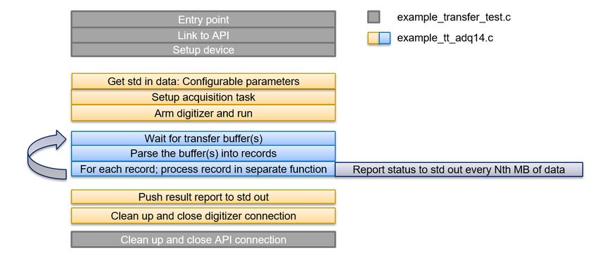
3.2.1 Source files
• example_transfer_test.c - Holding the main() entry point and the ADQAPI connection setup.
• example_tt_adq14.c - The code performing the test.
• ADQAPI.h - The header file for the installed API (contains all API commands)
3.2.2 Flow
3.3 Tools
The application is written in the programming language C and requires an appropriate C compiler to be
used. In Windows it can be used with for instance Visual Studio from Microsoft and in Linux it is typically
compiled with the gcc components.
System transfer speed test - App Note www.teledyne-spdevices.com Page 4 of 12Classification Revision
Open A
Document ID Print date
19-2245 2019-03-01
� Note
Make sure that you have selected the appropriate 32-bit/64-bit target selection for the OS you intend
to run the application on.
4 Running the application
4.1 Configurable parameters
There are a number of parameters that can be chosen to provide the test you desire to perform. These
are chosen run-time by the user in the console.
� Tip
These parameters can also be inserted automatically with redirecting a file into standard input. There is
a file params.txt in the example directory that contains the default run-time parameters. The example
is run with taking these parameters from the file by issuing ”ADQAPI_transfer_test_example.exe <
params.txt” from the command window
• Configuration Mode This sets the way to configure the test. 0 will just run with default settings,
1 will enable test configuration and 2 will enable test configuration and the advanced settings.
• Parsing Mode This sets the mode of parsing. 1 is full parsed mode (DEFAULT), 2 is non-user
parse mode and 3 is raw mode. Full parsed mode generates records to the user, the other two
does not parse into records. Raw mode can be used together with offline parsing methods. Mode
3 will have the highest performance, mode 2 slightly less and mode 1 the least performance - due
to the host PC load inferred by the different modes.
• Desired run time This sets the number of seconds for the test to run. 0 is a 30 second run (DE-
FAULT). Using -1 will make it an infinite run. However, infinite runs will not generate any final
reports, as when interrupted it will break immediately.
• Desired transfer speed to test. Sets the test data generation speed in MB/s. 1024 MB/s (DE-
FAULT). The test will auto-configure from this parameter and the trigger rate to select a record size
and amount of channels that will produce the correct amount of data.
• Desired trigger rate to use. Sets the trigger rate in Hz to use. 1 kHz (DEFAULT). The test will
auto-configure from this parameter and the desired transfer test speed to select a record size and
amount of channels that will produce the correct amount of data.
� Note
A higher trigger rate will use shorter records to provide the amount of data generation requested.
As a consequence this will create more records and thus also more data overhead.
• Number of kernel buffers. [Advanced] Sets the number of kernel buffers to use. 32 is DEFAULT.
• Size of kernel buffers. [Advanced] Sets the size of kernel buffers to use for allocation (in MBytes).
4 MB is DEFAULT.
System transfer speed test - App Note www.teledyne-spdevices.com Page 5 of 12Classification Revision
Open A
Document ID Print date
19-2245 2019-03-01
� Warning
On Linux systems contiguous memory area may be very limited by the system configuration.
One some Linux versions CMA settings may be changed to support higher allocations.
• Periodic report interval. [Advanced] Sets the amount of data in Mbytes transferred for the periodic
report to be output. 1024 MB is DEFAULT.
System transfer speed test - App Note www.teledyne-spdevices.com Page 6 of 12Classification Revision
Open A
Document ID Print date
19-2245 2019-03-01
4.2 Test case setup report
The test auto-configures from the set parameters and reports back the chosen settings and some vali-
dation and warnings are provided for checking that the test case is reasonable.
4.2.1 Default setup
Here is what it looks like using the default configured test.
The application will make a rough self-assessment of the expected capability vs the configured test
case and report whether it expects the test to pass OK or not. If everything looks OK, press ENTER to
start the test.
System transfer speed test - App Note www.teledyne-spdevices.com Page 7 of 12Classification Revision
Open A
Document ID Print date
19-2245 2019-03-01
4.2.2 Configured setup
Here is what it looks like, when configuring it for Full parse mode / 30 seconds of run-time / 1024 MB per
second / 500 Hz trigger rate:
The application will make a rough self-assessment of the expected capability vs the configured test
case and report whether it expects the test to pass OK or not. If everything looks OK, press ENTER to
start the test.
System transfer speed test - App Note www.teledyne-spdevices.com Page 8 of 12Classification Revision
Open A
Document ID Print date
19-2245 2019-03-01
4.3 Reporting during run
4.3.1 Status flow
A ’W’ character is written each time the application calls waitingfortransferbuffers. For each time there
is more than zero buffers, that number is printed. If it exceeds 9 buffers, a ’N’ character is printed. This
repeats for the extent of the test, these printouts are only interrupted by any periodic reports or indications
produced.
4.3.2 Periodic report
For every PRINT_EVERY_N_MBYTES_DEFAULT MBytes passed (default is 1024 MB) an intermediate
report on results are produced. Can be configured to other value in advanced mode. It looks like this:
4.3.3 Indications
• Streaming overflow detected
[ERROR] Streaming overflow detected.
This means that there has been an overflow in the system and data has been lost. The test will
terminate as unsuccessful and produce a final report.
• Maximum kernel buffer fill level detected
[WARNING] Maximum buffer fill level detected.
This means that kernel buffers are exhausted. Overflow is imminent to occur.
• High kernel buffer fill level
[WARNING] High buffer fill level detected.
This means that kernel buffers are on the limit of getting exhausted. All data is currently OK but
this is an indication that long-time operation may not be robust with these settings.
• High DRAM buffer usage
[WARNING] High DRAM usage.
System transfer speed test - App Note www.teledyne-spdevices.com Page 9 of 12Classification Revision
Open A
Document ID Print date
19-2245 2019-03-01
This means that FPGA DRAM buffers are used to more than 75% . This is an indication of that
application is not emptying the transfer buffers fast enough and an overflow may be the result soon.
• Significant DRAM buffer usage
[WARNING] Significant DRAM usage.
This means that FPGA DRAM buffers are used to more than 25%. This is an early indication of
possible robustness issues - host not emptying buffers fast enough, but if they stay at this level
there is no problem.
System transfer speed test - App Note www.teledyne-spdevices.com Page 10 of 12Classification Revision
Open A
Document ID Print date
19-2245 2019-03-01
4.4 Interpretation of final results
Before the final report is issued the application will read out the maximum DRAM fill level during the test.
4.4.1 Passed test
The passed result is shown by the line
[RESULT] Test OK. All data transferred without detected problems.
System transfer speed test - App Note www.teledyne-spdevices.com Page 11 of 12Classification Revision
Open A
Document ID Print date
19-2245 2019-03-01
4.4.2 Failed test
In this case we select, by intent, a configuration that will fail (too high transfer rate for the interface and
host controller).
The failed result is shown by the line
[RESULT] Test FAILED. Transfer errors occurred.
System transfer speed test - App Note www.teledyne-spdevices.com Page 12 of 12Worldwide Sales and Technical Support
www.teledyne-spdevices.com
Teledyne SP Devices Corporate Headquarters
Teknikringen 6
SE-583 30 Linköping
Sweden
Phone: +46 (0)13 645 0600
Fax: +46 (0)13 991 3044
Email: spd_info@teledyne.com
Copyright © 2019 Teledyne Signal Processing Devices Sweden AB
All rights reserved, including those to reproduce this publication or parts thereof in any form without permission in writing from Teledyne SP Devices.You can also read