Taking Apart an iPod Touch 2nd Generation
←
→
Page content transcription
If your browser does not render page correctly, please read the page content below
Taking Apart an iPod Touch 2nd
Generation®
By R. G. Sparber

Copy left protects this document1.

Disclaimer: Although I’ve done my best to create an accurate and safe procedure
for opening an iPod Touch, I cannot be held responsible for any damage. There is
no substitution for experience. I broke the frame, display, and put the battery in
backwards the first time I tried replacing the battery. My goal here is to help you
avoid these mistakes and hopefully bring your iPod Touch back to full
functionality without mishap.

Background
Having just recovered from mangling my beloved iPod Touch, I felt compelled to
document what I should have done. All of the instruction I found online gave the
overall procedure but none had enough detail to keep me out of trouble. I just
wanted to replace the battery. After 1 ½ years of charging cycles, it was failing to
hold a charge. I ended up breaking the frame of the digitizer, cracking the
digitizer, and shattering the LCD. The good news is that my iPod is back in working
order now and it only cost me $6 for the battery and $15 for the LCD. For now I
am living with the hairline crack in the digitizer. A new one cost about $15. A bit
of Superglue fixed the frame.

Hindsight
I’m not so sure I would go this route again. Apple charges $80 to replace the
battery plus $7 for S/H. Say it cost me $7 to ship it to them. We are talking about
$94 total. If my local Apple store can do it, the cost might be less. By replacing the
battery myself with no better luck, I’m looking at $36 (battery, LCD, and digitizer)
not counting my time nor the un-definable risk factor.
1
    You are free to copy and distribute this document but please do not modify it.
                                Page 1 of 20 July 9, 2010 R.G. Sparber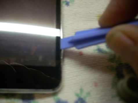
If I did change another battery, I would assume that I would need to replace the
battery, LCD, and digitizer. This would make it a lot easier to open the case since I
wouldn’t have to be as careful.

Opening the case does involve cutting the rubber seal between faceplate and
shell. I made no effort to restore this seal so any excessive moisture on the
faceplate might find its way inside and do permanent damage.

I do wonder if the reason Apple charges so much is because they have similar
problems.

I recommend that before you buy any replacement parts, read over this
procedure and decide for yourself if the benefit outweighs the risk. My wife’s iPod
Touch will need a new battery soon and I told her to take it to Apple.

                      Page 2 of 20 July 9, 2010 R.G. Sparber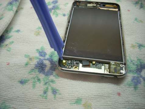
The Crux of the Problem
Before I get into the sequence needed to safely open the iPod Touch, let’s look at
the way the front frame attaches to the shell. I will go into more detail during the
procedure.

Buried deep inside the iPod Touch is this metal tray. Along the left and right sides
                                                 are the square clips. There are 4
                                                 clips on the right side and 3 on
                                                 the left.

                                                  These clips are very difficult to
                                                  see when viewed from above
                                                  because they are rather thin.

                     Page 3 of 20 July 9, 2010 R.G. Sparber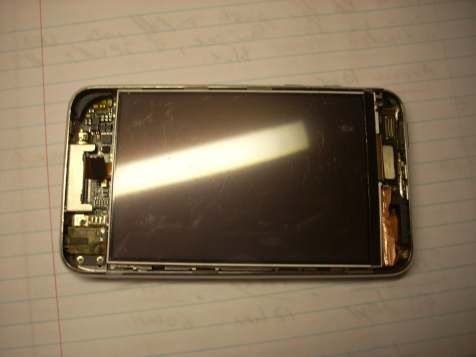
These
 hese clips engage the front frame
                             frame. Note the square recess with the tiny ledge
outlined with the red box below
                          below.. You are looking from outside of the frame.

When the frame is pressed into the square clips, the two lock together.

The trick when opening the iPod Touch is to find each of these clips and release
them one at a time. Any other prying is both futile and potentially damaging. I
should know, I did a lot of damage.

Overview
The general steps are

   1.   Sync the iPod Touch and turn off its power
   2.   Breakk the seal between front frame and body
   3.   Release the clips and lift up the frame (the hardest step)
   4.   Disconnect the cable from front frame to circuit board and lay the front
        frame with its digitizer aside
   5.   Remove one screw which is not under the display
   6.   Lift up LCD display enough to access the screws holding the metal tray
   7.   Remove all screws under the display
   8.   Lift out metal tray

   At this point you have access to the battery, the digitizer, and display.

   Replacement of the battery involves heating a ribbon cable with a small
   soldering iron and lifting it off of the circuit board. There is no connector. I
   recommend using very thin rosin core solder plus have some Solder Wick   Wick® in
   hand. If you don’t recognize these terms, I suggest you don’t learn on your
   iPod Touch.

                      Page 4 of 20 July 9, 2010 R.G. Sparber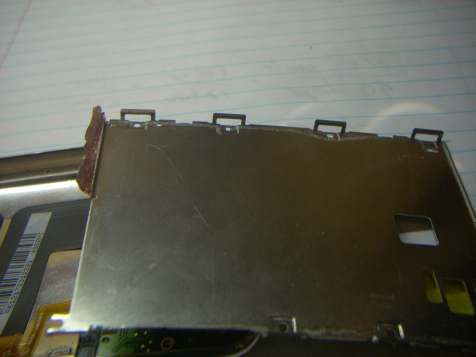
Replacing just the digitizer involves separating it from the front frame. The
   frame is very delicate and I broke it while trying to open my iPod Touch.
   Fortunately, a bit of Crazy Glue® enabled me to make the needed repair. I have
   seen digitizers that come with the frame. I suggest you buy it that way.

   Replacing the LCD display involves peeling off a small piece of metal foil and
   disconnecting a ribbon cable. Care must be taken when lifting up the LCD
   because any bending will crack the glass.

I replaced the battery and the display.

Before starting, I suggest you watch a few of the videos on YouTube related to
this subject. Although they lack detail, they do give you a general idea of what to
do.

                     Page 5 of 20 July 9, 2010 R.G. Sparber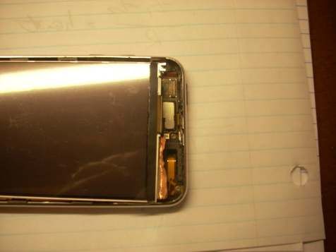
Detailed steps
I assume you are opening your iPod Touch in order to replace something. In the
package with that “something” should be a plastic pry tool. The tool I received is
good for opening a gap in the case but cannot survive prying. You will need a tiny
screwdriver for the screws and you can use it to release the clips.

   1. [ ] sync the iPod Touch
   2. [ ] set up your workplace
          a. find a place with good light
          b. put down something soft to prevent scratching but avoid anything
             that will generate lint that might get onto the glass surfaces of the
             iPod
          c. work at a comfortable height
          d. keep your hands very clean at all times
   3. [ ] remove any screen protector plastic from front of iPod Touch and throw
      it away
   4. [ ] hold down the button in the upper left corner until you see a prompt to
      turn off power. Slide the arrow over to the right to turn power off.

                     Page 6 of 20 July 9, 2010 R.G. Sparber
5. [ ] using the plastic tool, work it into the gap between front frame and
   body near the volume control button. Only push straight down and slide it
   along the gap to cut the rubber seal. Do not twist the tool as this can break
   the frame and even the display. I speak from experience here. Bummer.
6. [ ] With patience, you will eventually be able to slide the tool around the
   entire perimeter of the front frame. At all times the wedge should point
   straight down into the gap.

                  Page 7 of 20 July 9, 2010 R.G. Sparber
7. Overview: Rather than try to take a picture of how the clip engages the
      faceplate frame, here is an exploded drawing.

                                                         Starting at the outside is the
                                                         metal shell outlined in blue.
                                                                          Then we have
                                                                          a metal clip
                                                                          marked in red
                                                                          and also
                                                                          shown in the
                                                         picture here. The metal clip
                                                         sits in the clip recess molded
into the faceplate frame.

I have drawn the view you would see if the metal shell was transparent. In this
drawing you see the metal clip, in red, captured by the clip recess shown in green.
The recess is part of the faceplate frame shown in black. By prying the metal clip
out of the recess, you release the frame. With the frame released, you can pry it
up enough to keep the clip out of the recess. When all clips have been released,
the frame will come up. Lift it just enough to clear all clips. We still have a cable to
disconnect.

                      Page 8 of 20 July 9, 2010 R.G. Sparber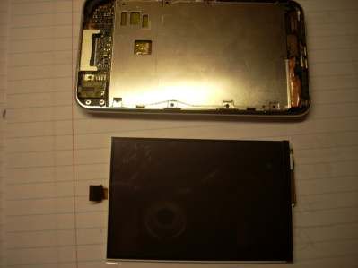
8. [ ] Time to do the task:
                                              Near each clip location shown
                                              here with an arrow, push down
                                              on the plastic pry tool enough to
                                              see the top of the clip. Then use
                                              a small flat screwdriver to very
                                              slightly bend the clip toward the
                                              outside perimeter. At the same
                                              time, gently pry up to raise this
                                              area of the frame just enough so
                                              the clip does not re-engage. You
                                              have to look very close to see
                                              the edge of each clip.

                                              This step is by far the hardest
                                              one to complete.

9. [ ] After you have release all seven clips and raised up the frame, you can
   pivot the frame up by lifting the bottom end while keeping the top end
   down. There is a cable that goes from the frame to the top left corner of
   the circuit board attached to the body.

                                                                      top

   I have drawn a white box around this connector. With the cable
   disconnected, you can completely remove the front frame with its attached

                  Page 9 of 20 July 9, 2010 R.G. Sparber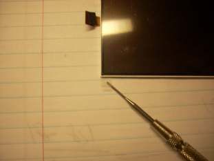
digitizer. I recommend you do not touch the glass. I put mine in a clean
   plastic sandwich bag and sealed it up. Inspect the frame for damage. If torn,
   you may be able to repair it with Crazy Glue®.
10.[ ] Near the connector, find a screw that holds the metal tray to the body.
   See arrow above. Remove this screw with a “000” Philips head screwdriver
   and put it in a safe place. These screws are amazingly small and easily lost.
   The iPod Touch has been carefully designed for lowest cost so understand
   that every screw is essential.
11.[ ]

   The LCD can now be pivoted up. You can use the plastic pry tool to lift it up
   a little but then hold it in your fingers. Take care not to bend the display as
   this will crack it. I found thin strips of double sided tape holding the display
   to the metal tray. There is a strip of copper foil glued to the upper right
   edge. It is marked above with the blue box. This foil acts as a hinge. It tears
   easily so take it slow.
                  Page 10 of 20 July 9, 2010 R.G. Sparber
12.[ ] Under the display you will find seven screws, one at each clip. Remove
all of them.
top
You can see at the arrows the screw holes that are under the metal tray.
The white arrows are the screw under the display while the red arrow is
that odd one you removed before raising the display.
13. [ ] With all screws removed, you can lift the tray enough to see two cables.
One cable is soldered to the board. You can see this connection in the
above picture inside the white box. The other cable terminates on a
connector shown inside the red box. Gently pull on this connector by
pulling on its cable and it will come off.
14. [ ] It will now be possible to pivot the tray up being careful not to stress
the power cable.
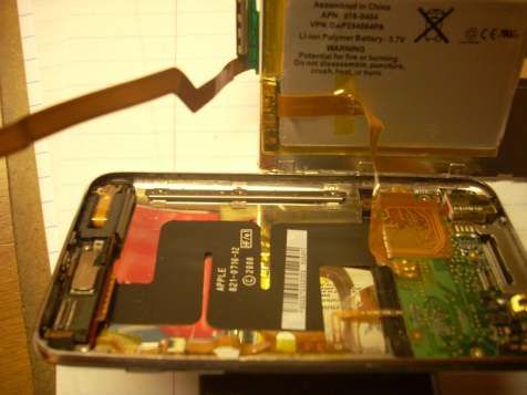
15. [ ] If you are not replacing the battery, just skip these steps.
a. [ ] The battery is held on the back of the metal tray with two strips of
double sided tape. Using the plastic pry bar, gently separate the
battery from the tray.
b. [ ] You will find very tiny text printed on the cable nearer where it is
soldered to the board. Mine read “PAP-29-X”. Record this text for
future reference: __________________________.
Page 11 of 20 July 9, 2010 R.G. Sparberc. [ ] There is a square of Kapton® tape over the soldered end of the
cable. Remove the tape and put it in a safe place.
d. [ ] Under the tape are three square lands with solder on them. As
shown above, the top and middle lands connect to much less copper
than the bottom one. This means that it won’t take much heat to
reflow the solder and peal the top and middle pads up from the
board. The bottom one connects to a ground plane and will take a lot
more heat/time to desolder. Take care not to short the outer two
lands together since that will short out the battery.
e. [ ] With the power cable removed, used the Solder Wick to clean up
and re-tin the pads on the circuit board.
f. [ ] take the new battery and position it over the tape that is stuck to
the metal tray. Note in the picture below how the battery is centered
side to side on the tray with the left edge lined up with the left
bottom edge of the metal tray. The text should be showing and the
power cable exposed. Be careful not to run this cable between the
tray and the battery.
Page 12 of 20 July 9, 2010 R.G. Sparbertop
g. [ ] Verify that you have the correct text (see step b) facing up before
soldering on the power connections. On my battery, there is a “P+”
and “P-“ on the side of the power cable that faces the circuit board.
Tin these pads that will face the board. Hopefully you will be able to
follow these instructions and not solder the cable in up-side-down. If
you do, you may not blow up the iPod but I have found that it does
damage the battery. I recommend you toss the battery and buy a
new one.
h. [ ] Align the power cable so the white line closest to the 3 pads is
even with the edge of the circuit board. Then apply heat to the
center pad while pushing down with a small wooden rod (something
non-conductive yet able to stand the heat). When the solder flows,
remove the heat but keep pressure with the rod. Once the solder has
cooled, remove the rod and verify that the cable is still in proper
alignment. Reheat as necessary.
Page 13 of 20 July 9, 2010 R.G. Sparberi. [ ] Apply heat and pressure to the top pad. The solder should reflow
about as easy as the center pad.
j. [ ] Apply heat and pressure to the bottom pad. This is the one
connected to ground and will take a lot more heat and time. When
the solder flows, remove the iron but keep pressure on until it cools.
k. [ ] When the pads are cool to the touch, replace the square of
Kapton tape over them.
Page 14 of 20 July 9, 2010 R.G. Sparber16. [ ] If you are not replacing the LCD display, skip these steps.
top
a. [ ] There is a strip of copper tape seen inside the white box above.
Using your plastic pry tool plus a tweezers, tease this tape off of the
display while leaving it attached to the metal tray. Do not touch the
adhesive on the tape. Be gentle, the copper tears easily. I know
because I tore it little.
Once the tape has been
lifted, you can remove
the display from the
metal tray.
Page 15 of 20 July 9, 2010 R.G. Sparberb. [ ] My new display came with a plastic sheet stuck to its mirrored
back. Leave this plastic in place for now. Place the display in the tray
with the cable under the tray and not between the display and the
tray. The connector should be visible on the left side as shown above
inside the green box.
c. [ ] Using your fingers, form the copper tape around the display until
it sticks.
d. [ ] align the connector over the board-mounted socket shown inside
the red box below, and press down. You should be able to feel it snap
into place.
top
e. [ ] If the battery is correctly positioned on the back of the metal tray,
the tray should snap down onto its rails and you should see the screw
holes through the tray. If necessary, reposition the battery so the
tray seats properly.
Page 16 of 20 July 9, 2010 R.G. Sparber17.[ ] Take a close look at the screws you removed. There should be one that
is longer than the rest. I’m not positive, but I believe this one goes into the
hole in the bottom right corner of the tray near the sound jack. Select one
of the other screws and screw it partially down in the area shown below
with the white circle.
top
Page 17 of 20 July 9, 2010 R.G. Sparber18.[ ] Pivot the display up being careful not to tear the copper tape. Here is a
picture of the metal tray removed but it does show you screw locations.
top
Loosely screw in the long screw at the location marked with the white
arrow.
19.[ ] Loosely screw in the remaining short screws into the rest of the holes.
20.[ ] Tighten all seven screws.
21.[ ] Before lowering the display down for the
last time, remove the plastic cover, if present,
from its back. You can barely make it out at
the tip of my screwdriver.
22.[ ] Using a small quantity of glass cleaner and
a lintless cloth, carefully clean the display.
Use a strong light to verify there are no
specks of dust or debris on the surface.
Page 18 of 20 July 9, 2010 R.G. Sparber23. [ ] Locate the top frame with attached digitizer. Clean both sides of the
glass taking care not to press too hard. Inspect for dust and debris with a
strong light.
24.[ ] Being careful not to touch the glass, stand the frame on end such that
the digitizer cable is near its socket outlined below with a white box.
top
25. [ ] Press down on the connector until it snaps in place.
26. [ ] Before buttoning things up, we need to be sure the iPod works. Push
down on the power button in the upper left corner. The iPod Touch should
spring to life. If you get nothing, it might be that the new battery is dead.
Before tearing it open again, try attaching a USB cable to furnish power. If
the iPod Touch is still dead, retrace your steps to be sure all cables are
plugged in and all power connections are sound. Assuming that all is well,
let’s continue.
27. [ ] Hold down the power button until you get the power off prompt again.
Use the slider to turn off power.
28. [ ] Gently press down on the frame as it engages those square clips. Press
evenly all around to prevent twisting of the frame. Now is not a good time
to break this extremely fragile frame.
29. [ ] With the frame fully engaged, do a final check that the iPod Touch is
operational. Congratulations! You have mastered the disassembly and
reassembly of the iPod Touch 2nd generation.
Page 19 of 20 July 9, 2010 R.G. SparberWhat next?
You will, no doubt, find errors and bits of confusion in this procedure. Please send
me your insights so I may improve this document for the next person needing to
replace a battery or display.
Rick Sparber
rgsparber@AOL.com
Page 20 of 20 July 9, 2010 R.G. SparberYou can also read