THE BEST-SELLING ENGINE OF ALL TIMES IN AVIATION HISTORY - 8.92 MB
←
→
Page content transcription
If your browser does not render page correctly, please read the page content below
ISSUE
The Periodical of TUSAS Engine Industries, Inc. (TEI).

TEI IS NOW GLOBALLY THE BIGGEST SUPPLIER OF “LEAP” ENGINE,
THE BEST-SELLING ENGINE OF ALL TIMES
IN AVIATION HISTORY
The ÖRS project blaze a trail
for our country and industry

We all together have had great
time at TEI's picnic organization

TEI continues to establish new
cooperation with universities
İŞ SAĞLIĞI VE GÜVENLİĞİ

           02
TEI POST

   03
TABLE OF CONTENTS                                                   EDITORIAL

05 / MESSAGE FROM THE PRESIDENT & CEO                               Dear TEI Post Readers,

06 / COVER STORY                                                    We are happy to meet you with our 131st issue in early
         TEI IS NOW GLOBALLY THE BIGGEST SUPPLIER OF “LEAP”         2017.
         ENGINE, THE BEST-SELLING ENGINE OF ALL TIMES IN
         AVIATION HISTORY                                           Our "Cover Story" in this new issue features Advanced
                                                                    Manufacturing Technologies Building, which was
09 / ACTIVITIES & PROJECTS                                          inaugurated on September 21, 2016.
         PROJECTS
                                                                    We appreciate your valuable participation in "TEI Post
         HR PROCESSES
                                                                    Satisfaction Survey" which was held for the first time to
13 / NEWS ABOUT TEI                                                 learn about your opinions on our magazine. We remain
                                                                    committed to improving our magazine in light of the
20 / TECHNICAL ARTICLE                                              feedback from you.
26 / NEWS ABOUT THE AVIATION INDUSTRY
                                                                    In this issue, we have covered Eskisehirspor, the football
32 / NEWS ABOUT OUR EMPLOYEES                                       team of our city, based upon your requests. In addition, as
                                                                    per your requests, we present posters with this issue for
35 / VISITORS                                                       the first time in our history.
38 / EXHIBITIONS AND ORGANIZATIONS
                                                                    Burak Balci and Mujdat Aslan again will take part in
40 / ENVIRONMENTAL AND OCCUPATIONAL SAFETY                          this issue with articles on sports and aviation safety on
                                                                    our column “By TEI Staff”; we would like to take this
42 / EVENTS                                                         opportunity to thank them once again and remind you all
                                                                    that all TEI staff are welcome to contribute our magazine
46 / SOCIAL RESPONSIBILITY
                                                                    with their articles.
48 / BY TEI EMPLOYEES
                                                                    See you in our 132nd issue...
56 / HOBBIES OF OUR EMPLOYEES
         ILKER KURTULUS - “MUSIC REPRESENTS MY IDEA OF LIFE”
         SEMIH KOSEOGLU - PALUDARIUM BRINGS NATURE INTO
                                                                    For and On Behalf of TEI             Head Office Address
         YOUR HOME!
                                                                    Prof. Mahmut F. Aksit                TUSAS Engine Industries, Inc.
58 / ACHIEVEMENT BOARD                                              Executive Editor
                                                                                                         Esentepe Mah. Cevreyolu Bulvari
                                                                                                         No: 356 26003
59 / SOCIAL CLUBS                                                   K. Levent Tufekci
                                                                                                         Tepebasi / Eskisehir - Turkey
                                                                    Managing Editor                      Tel: +90 (222) 211 21 00
60 / TRAVEL
                                                                    Duygu Gokduman Pilatin               Fax: +90 (222) 211 21 01
         LET'S TAKE A HISTORY, CULTURE AND NATURE TOUR                                                   www.tei.com.tr
                                                                    Editorial Board
         IN THE BALKANS BY SAMET ASLAN                              Senay Dortkasli                      Publisher
         GOYNUK, TARAKLI, YEDIGOLLER BY FATIH OZCAKIL               Doruk Kocer                          Dumat Ofset Matbaacilik San. Tic. Ltd. Sti.
                                                                    Tugba Onder                          Bahcekapi Mah. 2477 Sok. No: 6
70 / PERSONAL DEVELOPMENT                                           Erkan Balk                           Sasmaz / Ankara
         PROF. ACAR BALTAS - CAREER SUCCESS, SATISFACTION,          Editor
                                                                                                         Tel: +90 (312) 278 82 00
         HEALTH AND LONGEVITY                                       Kadriye Yuzeroglu                    Edition Period
                                                                                                         Jan - June 2017
73 / HEALTH                                                         Visual Director
                                                                    Emre Ergul                           Publication Type
          ACIBADEM INSURANCE - NECK PAIN MAY BE A SIGN OF                                                Regional Periodical
                                                                    Production
          CERVICAL DISC HERNIATION!
                                                                                                         Published Date
75 / ANNOUNCEMENTS FROM TEI                                                                              24 Nisan 2017

                                                                    All rights are reserved on behalf of TUSAS Engine Industries, Inc.

                                                               04
MESSAGE FROM THE PRESIDENT & CEO

TEI: THE LEADING

SUPPLIER OF LEAP ENGINE
I
   'm happy to meet you again with the 131st issue of               projects at a quick pace. As we sustain the TEI
   our corporate magazine TEI Post. First, I would like             Intelligence Workshops project, which was launched in the
   to thank all TEI employees for their contributions               first half of 2016, we have also entered the second term of
   throughout 2016, which turned out to be successful               Vocational High School Coaching Program, a collaborative
year on our way to accomplish our vision of "To be                  initiative with Private Sector Volunteers Association. I
globally competitive, original power systems OEM". In               would like to thank all TEI employees who volunteered to
the second half of 2016, we saw numerous significant                support these projects.
achievements and developments, including inauguration
of our Advanced Manufacturing Technologies Building in              Besides all these good news, we also experienced a
particular. Thanks to this investment, we are now one of            deep sorrow in 2016 at TEI family. Our beloved colleague
the two facilities, manufacturing blisk parts of the LEAP           Serhan Kurt passed away. I extend my sincerest
engine, along with GE. Furthermore, we have become                  condolences to all TEI staff and his family.
the largest global supplier for the LEAP engines, the most
preferred next generation commercial engine to power                With your invaluable supports, I believe that 2017 will be
Boeing 737Max and Airbus 320Neo commercial aircraft.                a milestone for our company. I have absolute faith that
                                                                    our success in parts manufacturing will be reinforced
Also, during this period, we attended the Farnborough               with our successful initiatives in R&D projects, which
International Airshow, one of the most prestigious trade            will contribute, to the targets of our company, and we
shows in global aviation industry, and Istanbul Airshow,            move forward with firm steps toward being a globally
the most prominent aviation organization in Turkey, to              competitive company and the one in the national market.
display the 1:1 scale models of Turkey’s first indigenous
TS1400 turbine engine to power the Original Turkish                 I hope 2017 turns out to be a year of happiness, health
Helicopter and PD170 engine being developed for                     and well-being for the entire TEI family.
Medium-Altitude Long-Endurance (MALE) unmanned
aerial vehicles.                                                    Greetings and best regards,

In addition to the achievements we demonstrated in our              Prof. Mahmut F. Aksit
activity areas, we also maintained our social responsibility        President & CEO, TEI

                                                               05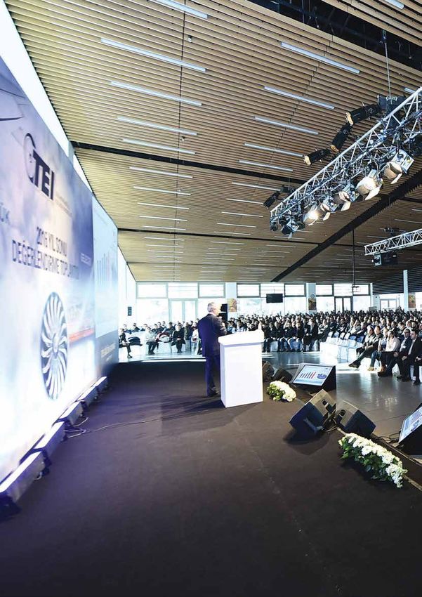
COVER STORY

TEI IS NOW GLOBALLY THE BIGGEST SUPPLIER OF "LEAP" ENGINE,

THE BEST-SELLING ENGINE OF ALL
TIMES IN AVIATION HISTORY

T
        EI, the leading aviation engines manufacturer in            "Next generation" digital building
        Turkey, inaugurated its Advanced Manufacturing              TEI President and CEO Prof. Mahmut F. Aksit gave the
        Technologies Building with an opening ceremony on           keynote speech at the opening ceremony, underlining
        September 21. Fikri Isik, Minister of Defense, Nabi         TEI's position as the leading supplier of LEAP engine
Avci, Minister of Culture and Tourism, Azmi Celik, Governor         parts globally thanks to this new investment in Advanced
of Eskisehir, General Hasan Kucukakyuz, Commander                   Manufacturing Technologies Building. He also noted
of Combatant Air Force, Harun Karacan, AKP Member                   that the building, which cost USD 110 million in total
of the Parliament for Eskisehir, Prof. Yilmaz Buyukersen,           including the manufacturing equipment it accommodates,
Metropolitan Mayor of Eskisehir, Ferhat Kapici, Chief Public        is a "next-generation" digital building, and it features
Prosecutor of Eskisehir, Prof. Naci Gundogan, President             a software system, which enables monitoring lighting,
of Anadolu University, Lt. Gen. (R) Orhan Akbas, Director           heating and cooling system as well as all machines
General of Turkish Armed Forces Foundation, Koksal Liman,           through a network.
Chairman at TEI, Muharrem Dortkasli, former CEO of TAI,
Mike Wilking, Chief Marketing Officer for Military Systems          In his keynote speech, Aksit also shared that exports
and Business Development at General Electric Aviation and           revenue of USD 2 billion is expected from the parts to be
many high profile delegates attended the ceremony which             produced at the Advanced Manufacturing Technologies
represents a significant milestone for both TEI and the             Building over the next two decades, and reminded that at
industry.                                                           least one in every two civil aircraft currently in operation

                                                               06
TEI POST

  Advanced Manufacturing Technologies Building is put into
  service with a ribbon-cutting ceremony at the stage.

                                                                     Fikri Isik, Minister of Defense,
                                                                     Nabi Avci, Minister of Culture and Tourism.

TEI, the leading supplier of LEAP engine parts globally,
inaugurated its Advanced Manufacturing Technologies Building
with a splendid ceremony. Export revenue of nearly USD
2 billion is expected by 2035 from the engine parts to be
produced at this "next generation" building.

worldwide is equipped with the parts produced by TEI.                                                          Prof. Mahmut F. Aksit
He also briefly mentioned about TEI's targets, noting:
"We aim to increase this ratio to 3/5 and 4/5 from 1/2 and
position TEI at the top place in global aviation industry.
We also aim to double and triple our total sales revenues,
which was USD 260 million as of the year-end of 2014,
in the next 10 and 20 years, respectively. Currently the
total value of the firm orders we received is around USD 3
billion. Considering that our total revenues for the previous
year realized at USD 300 million, we can say that we have
guaranteed our company's future for the next 30 years.
We are going to make a giant leap thanks to our new
investments."

"Future investments are on the way"
Mike Wilking, Chief Marketing Officer for Military Systems
and Business Development at General Electric Aviation
spoke after Prof. Mahmut F. Aksit, expressing their

                                                                07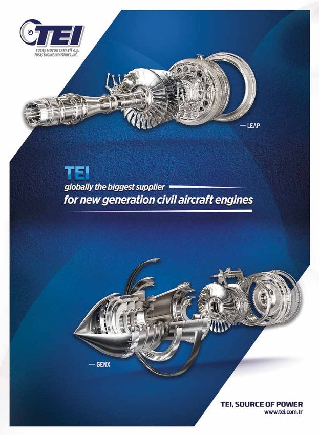
COVER STORY

happiness to see TEI become a leading engine part                     At the opening ceremony, company ID cards were presented
manufacturer globally during their partnership for over 30            to 31 new employees who completed the On-the-Job Training
years, and noting that future investment are on the way.              Program conducted by TEI in coordination with the Ministry
Nabi Avci, Minister of Culture and Tourism and Member                 of Education and Ministry of Labor and Social Security and
of the Parliament for Eskisehir was also present at the
                                                                      joined TEI.
ceremony and gave a short speech, highlighting the
importance of TEI to Eskisehir. He underlined that besides
its valuable contributions to the industry, TEI also created           ADVANCED MANUFACTURING TECHNOLOGIES
a great value for social life in Eskisehir with the social and
educational projects it undertook.
                                                                       BUILDING FOR THE FUTURE OF
                                                                       MANUFACTURING
"TEI is a source of pride for Turkey"
Minister of Defense Fikri Isik gave the final speech at the            • One of the two plants capable of producing compressor
opening ceremony, underlining TEI's achievements so                      blisks for the LEAP engine worldwide,
far: "TEI is a source of pride for Turkey as it has become
                                                                       • USD 10 million invested in building. Investments in 100
a leading global engine part manufacturer and turned
                                                                         machines with a total cost of USD 100 million to be
Eskisehir into an important center in this area.
                                                                         completed by 2019,
Companies which have faith in Turkey always win; and                   • 300 people will be employed,
General Electric represents a good example of this fact,"              • More digital application for paperless manufacturing,
he noted and went on to say: "This opening ceremony
                                                                       • Sales revenue of around USD 2 billion by 2035.
marks a very important milestone. We are also engaged
in some good and promising investments. We have
built a fully indigenous diesel engine for our national
unmanned aerial vehicles. Now, we aim at a production of
an indigenous aircraft engine, which will not be subject to
any restrictions by third parties and exported worldwide.
Turkey will have built a fully indigenous original aircraft
engine within the next five years. And TEI will make it
happen in Eskisehir."

Minister Isik congratulated TEI President & CEO Prof.
Mahmut F. Aksit and all TEI managers and employees on
their outstanding efforts before ending his speech.
Finally, the Advanced Manufacturing Technologies Building
was put into service with a ribbon-cutting ceremony at the
stage. Minister of Defense Fikri Isik and Minister of Culture
and Tourism Nabi Avci visited the manufacturing site and
together they pushed the button to launch production of
blisk parts for use in next generation engines.

                                                                 08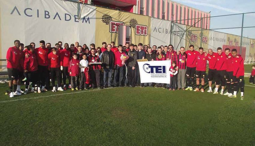
ACTIVITIES
                                      TEI POST
                                          AND PROJECTS

ACTIVITIES IN THE SECOND HALF OF 2016
PROJECTS                                     LEAP ENGINE BLISK MANUFACTURING

                                             TEI continues its activities under LEAP engine blisk
                                             manufacturing project. The following works were
                                             completed in the second half of 2016 or are still in
                                             progress as part of the project:
                                             • B1000 Building, which has been designed by using lean
                                               manufacturing principles and supported with digitization
                                               applications under industry 4.0 scope to provide high
                                               level productivity, was opened in September 21, 2016.
                                             • As part of the project, new part introduction processes
                                               have been completed for all blisk stages and serial
                                               production started in B1000 building.
                                             • Inertia welding, vertical turning, 5-axis milling, CSM
                                               (Curved Slot Mill), grinding, balancing and CMM
                                               machines were installed and put into service as part of
                                               the project.

LEAP Engine Stage 1-5 Blisks                 Advanced Manufacturing Technologies Building - LEAP Blisk Line

                                        09
ACTIVITIES AND PROJECTS

DEVELOPMENT PROJECT FOR THE TITANIUM                                 The national forging industry in Turkey supplies over 150 K
AND NICKEL SUPER ALLOY FORGING                                       tons of forged parts per year to domestic and international
                                                                     companies, operating mainly in automotive industry. The
TECHNOLOGIES IN AVIATION (ÖRS)                                       ÖRS Project will enable the establishment of a competitive
                                                                     supply network for titanium and nickel-based superalloy
                                                                     forged parts that can serve national and international
The ÖRS Project was launched on March 17, 2016 under                 engine programs in the mid- and long-term, and thus
the sponsorship of the Undersecretariat for Defense                  dependence on foreign sources will be significantly
Industries (UDI) with the aim of gaining titanium and nickel         reduced in national aviation industry.
super alloy forging technologies, which are not currently
available in Turkey despite their frequent use in gas turbine
engines worldwide.                                                   FULL AUTOMATION AND FAILURE PREVENTION

                                                                     Robot-aided marking application has been introduced
                                                                     with the Full Automation and Failure Prevention Project
                                                                     in "dot peen" marking operation, the most widely used
                                                                     part marking method in manufacturing. The project was
                                                                     designed by leveraging on TEI's know-how and realized
                                                                     in collaboration with a local company, providing 65%
                                                                     average reduction of operation hours.
                                                                     The following applications, classified in four main groups,
                                                                     were also put in place under the project.

                                                                     Occupational Safety
                                                                     • Security fence meeting applicable standards
                                                                     • Security door w/ automatic locking system
                                     Hot-Forged Sample Part          • Light barriers

                                                                     Failure Prevention Systems
Impellers made from Ti6Al4V (UNS R56400) and
                                                                     • Fully automated data entry with QR code
prototypes of turbine disks made Inconel718 (UNS
                                                                     • Part verification system
N07718) will be produced within the scope of project. In
                                                                     • Automatic program retrieval system
that respect, these materials will be forged by conventional
                                                                     • Positioning of workpieces at loading stations w/ high-
closed die hot forging, heat treated after forging and
                                                                       precision servo-controls
machined to get ultrasonic envelope geometries.
                                                                     • Pneumatic actuators for angular alignment of
Following the production processes, prototypes will
                                                                       workpieces
be subjected to mechanical and metallurgical tests
                                                                     • Identification of previously marked serial numbers
and inspections to determine whether the required
                                                                     • Record retention of the person performing the marking
specifications are achieved or not. Impeller and turbine
                                                                       process
disk geometries, belonging to TEI Turboshaft engine
                                                                     • Record retention of alarms
design, are selected as project target.
                                                                     • Probe system for marker pin length verification
Prime Contractor TEI
TEI taking the lead position as the prime contractor
for the project, subcontractors will be responsible for
development of hot forging and heat treatment processes
for the impeller and turbine disk. Metal Forming Center of
Excellence of Atilim University will also be supporting the
project team as project consultant on process modeling
and raw material characterization for prediction of forging
parameters.

With the ÖRS Project, titanium and nickel-based
superalloy forging capabilities will be acquired by national
industry for the production of aforementioned turboshaft
engine parts first, then other similar parts in different gas
turbine engines.                                                     Robotic Part Marking Station

                                                                10
TEI POST
Traceability ON-THE-JOB TRAINING PROGRAM
• All marked serial numbers stored in database
• Alarm function if same serial number marked previously This first phase of the on-the-job training program,
• Database containing operator, date and time records which was launched in January 2016 under the
• Password-authenticated administrator authorization for collaboration of TEI and Turkish Employment Agency to
special setting and program changes help inexperienced individuals gain some professional
and work experience, was completed. The second
Productivity phase was launched in August with 45 trainees from six
• Smart and common fixture design for loading of branches. Covering a six-month period, the program
different parts ended on December 31, 2016. The trainees will undergo
• Quick connection systems between fixture and loading an assessment process for recruitment based on their
station performances and current vacancies.
• One operator-double loading station configuration Furthermore, 27 trainees were selected as part of the
• Diameter, top surface and bottom surface marking of "Qualified Airmen" program launched in July under the
workpieces in one set-up leadership of Sabiha Gokcen Vocational and Technical
Anatolian High School, and the trainees started to attend
on-the-job training after completing the theoretical training
HR PROCESSES sessions at school. These trainees will be assessed for
recruitment based on their performances in 2017.
"TURBOSHAFT ENGINE DEVELOPMENT
PROJECT" RECRUITMENT PROGRAM TITLE-BASED PERSONAL DEVELOPMENT
TRAINING PROGRAMS
Program posters were hung on the notice boards of
relevant departments of universities to attract new-
graduates and experienced engineers to take part in
Turboshaft Engine Development Project and join TEI and
applications are collected under the theme "My National
Helicopter Engine".
A personal development training program was designed
for all white-collar employees in 2016. All personal
development processes were planned by title, matching
the competencies to be acquired as a result of the
trainings with the competency level required for each title.
7781 hours of training were delivered in total under the
program. An Outdoor Training was organized for leaders
as an outdoor activity called the "Future in the Skies" to
encourage teamwork and increase motivation.
11ACTIVITIES AND PROJECTS
TEI DEVELOPMENT CENTER PROJECT up a more fair and transparent system. A performance
committee, consisting of volunteering white- and blue-
TEI Development Center, a project for high-performing collar employees, has been formed for the project, and the
senior employees, continues with 3 modules and 72 relevant actions are executed by the senior management
trainees between October 2016 - February 2017. The and the committee in coordination. The project is expected
"Assessment Center" is applied at the beginning and end to be completed by 2017 including the software process.
of the program.
AWARD-APPRECIATION-RECOGNITION
A new Award-Appreciation-Recognition system was put
in place in 2016 with a special budget. In this respect,
Management and Employee Awards were defined and
put into practice. With the new system, the award and
recognition practices have shown a significant increase
across the company compared to previous years.
EXECUTIVE TRAINING
The Mini MBA program organized for our senior
management and executives ended and the participants
received their certificates. Personal development and
outdoor training programs were also organized for our
executives.
ORGANIZATIONAL RESTRUCTURING
OF WORKSHOPS
In 2015, lean manufacturing cells were created with
the part groups transferred under the responsibility of
Manufacturing Management and the engineers from other
relevant managements; and distribution of blue-collar
personnel was organized accordingly. In 2016, in addition
to this structure, a reorganization process was initiated to
enable monitoring of the workshop in a more controlled
LIFE COACHING manner and elaborate annual targets and performances
We have put in place a half-day long "life coaching" of blue-collar personnel. As part of the process, current
program to be organized two times a week to support technical assistance specialists were assigned as
employees professionally. As part of the program, an workshop supervisors so that six workshop supervisors
expert psychiatrist continues to provide consulting will be present in total in every shift. Supervision of
services at our On-Site Physician's Office. six blue-collar personnel has also been vested in six
technical leads working at Manufacturing Managements in
CONTINUOUS IMPROVEMENT PROJECT addition to their existing responsibilities. Technicians and
workstations under the responsibility of Manufacturing
We have rolled out the "Continuous Improvement Managements have been revised accordingly to reinforce
Project" to improve the performance system and set the workshop-based restructuring process.
12NEWS ABOUT TEI
MAIN ENGINE PROGRAMS
USING PARTS MADE BY TEI
GEnx
TEI produces 42 different parts including disks, spinners, seals, bearing
housings, casings and blisks for GEnx engines. The GEnx is the fastest-selling,
high-thrust jet engine in GE Aviation history with more than 1600 engines on
order. In addition to powering the four-engine Boeing 747-8, the GEnx engine
is also the best-selling engine for the Boeing 787 Dreamliner.
The GEnx engine represents a giant leap forward in propulsion technology,
using the latest materials and design processes to reduce weight, improve
performance and deliver a more fuel-efficient commercial aircraft engine.
The GEnx engine is also the world's first commercial jet engine with both a
front fan case and fan blades made of carbon-fiber composites.
TEI produces 18 different parts including shafts, disks and seals for the CFM56 engine, the best-selling
CFM56 jet engine in the world. The CFM56 engine set the standard for single-aisle commercial jet engines. With
more than 30,000 engines delivered to date, it powers Airbus A318, A319, A320 and A321 aircraft for
more than 550 operators worldwide.
F110 The F110 engine, which has a special meaning for TEI, currently continues to power best-in-class fighter
aircraft in 13 countries. TEI produces 60 different parts for this engine family including seals, disks, shafts,
mixing ducts, augmenter liners and flame holders. The F110 family provides industry-leading power for
F-15 and F-16 fighter aircraft and continuously infuses state-of-the-art enhancements for added mission
accomplishment.
13NEWS ABOUT TEI
GE90
TEI produces 20 different parts including seals, disks, impingement rings and seal supports for the
GE90, world’s largest turbofan engine built exclusively for Boeing 777 aircraft. The GE90 engine is
also the first-ever commercial aircraft engine using carbon-fiber composite fan blades.
LEAP
TEI produces 41 different parts, notably disks and blisks, for the new generation LEAP engines. The
LEAP delivers a 15% improvement in fuel consumption, compared to today’s most fuel-efficient engine
and will replace CFM56 engines as the most preferred commercial engine by airline operators. The
LEAP engine will power Airbus A320 Neo, Boeing 737 Max and COMAC 919.
CF6
For more than 40 years, the CF6 engine family has established an impressive operational record and
compiled nearly 400 million flight hours since they first entered commercial revenue service. TEI produces
34 different parts for this engine family, including spools, disks and shafts.
14TEI POST
TP400
TP400 is the most powerful Western turboprop engine producing 11,000
LM2500
shp. TEI not only contributed to the design process, but also produces
five main parts including FBS module, exhaust cone, primary nozzle and
The LM2500 is the most widely applied gas turbine,
IMC for the TP400 engine.
derived from CF6-6 aircraft engines, to power marine
platforms and for industrial applications. For the
LM2500 engine, TEI produces 36 different parts in total
including shafts, dome plates and torque shafts.
CF34
In early 1990s, the CF34 opened a new period in regional aviation; and recording over 100
million flight hours and more than 80 million flight cycles since then, it sets the standards
for performance, durability and reliability in this area. 8 different parts for CF34 jet engines,
including shafts and seals are produced by TEI. Considering the increasing demand, CF34
engines are expected to power more than 7500 regional aircraft by 2020.
GP7200
The GP7200 engine design comes from the
historic collaboration of two industry giants,
General Electric and Pratt & Whitney to power
Airbus A380. TEI produces 3 parts for this
engine including casings and stub shafts.
15NEWS ABOUT TEI
DESIGN, MANUFACTURING AND ITERATIVE METHODOLOGY OF CATHODE
TOOLS DEVELOPED FOR ELECTRO-CHEMICAL MILLING PROCESS
Parametric modeling technique has been developed for but cause pitting due to irregular electrolyte flow, should be
design and geometric adjustment of the cathode tool used smoothed by experience.
in processing of final geometry for the fan blades of the
blisks adapted to Electro-Chemical Milling (ECM) process.
After taking cross-sections of the fan blade, modeling
process for the immeasurable sections of cathode is
completed, enabling supply of a smooth electrolyte flow to
Figure 3. Set up for
the fan blade through the most outer platform. (Figure 1)
part and ECM cathode
Figure 1A Figure 1B positioning on the machine.
ECM process is a highly fast process; processing a blisk
with 70 fan blades takes around six hours. Following ECM,
vibratory finishing is applied to smooth the surface and
remove the layer of mud to make the part ready for shot peen
process. Then, the material of the surfaces where the part
contacts the ECM fixture is removed by a turning process
after the ECM; seal holes should also be drilled after final
Figure 1A: Cross-sections from fan blade geometry turning operation.
Figure 1B: Core modeling of the gap between the cathodes in the
Proper fan blade sizes and measures are obtained with ECM
cross-section taken.
process, and generally, no additional processing is necessary.
However, there might be some uneven surfaces on platform
A solid-state model is obtained through surface modeling
profile, which need additional processing. These areas
by using all the cross-sections. This model is used to
should be smoothed with robotic deburring process. Robotic
develop the concave and convex surface geometries of the
deburring is more repetitive compared to manual deburring as
fan blade.
it is more precise and programmed, and it is used to achieve
Once the fan blade geometry is developed, the platform the designed measurements for the platform profile.
surface between two fan blades and the radius of the
concave and convex bottom surfaces where the fan blade The cathodes are tried in ECM process and the measurement
meets the platform, are also modeled, giving the model its results obtained are assessed, and if any revisions are to
final form. be made on the cathode, the preset parameter values are
changed and the cathode model is updated. The cathode
Minimum 5-axis milling machines should be used for of the new project is not ready for production after the first
cathode manufacturing. The machine should have a fast- revision but requires several revisions for the adjustment of
rotating spindle, a high positioning repeatability and angular the fan blade geometry and correction of the platform profile.
milling capability. (Figure 2) After each revision, a trial cut should be performed and the
measures should be verified with CMM measurements. This
Figure 2A Figure 2B new method assigns 20 parameters to check concave and
convex profile of each cross-section and modify other length
and thickness measures. Considering that fan blade geometry
involves 12-15 measurable and 6-8 measurable cross-
sections, it is clear that there are at least 300 parameters to
check. All these parameters are recorded in a built-in sheet
and every iteration is also recorded on another sheet to create
Figure 2A: Machine set up for milling. a macro where all iterations are complied to check the model
Figure 2B Concave and convex cathodes processed by milling. geometry.
Cathodes produced by milling should be rubbed with felt Process development of stage-5 blisks for LEAP 1A/C and 1B
and sandpaper for deburring and edge finishing. Especially is completed was completed with this methodology before
those areas, which cannot be read through measurements proceeding to mass production.
16TEI POST
PRODUCT LIFE CYCLE MANAGEMENT PRACTICES
Product Lifecycle Management (PLM) is the process of just like operating system managing numerous software
managing all data and processes for a product throughout that we upload on it to use, PLM software manages
its the entire lifecycle from inception to end-of-life. The term various data by associating them with each other through
PLM originally comes from the design process of Rockwell integration with all software used across the company.
International's B-1B bomber, while its first application was
in 1895 at American Motors Corporation (AMC). [1] A common database is the main component of PLM
solutions. It creates a common database for all the data
The global PLM market has generated revenue of USD 40 generated for the same product by different teams within
billion as of 2015 and is projected to reach a market size the company. Thus, all the data for that product are
of USD 75 billion by 2022. [2] generated once in a single database and all teams can
access such data through a single platform whenever they
Globally, many leading companies in aircraft, aerospace need it.
and automotive industry, including General Electric,
Boeing, Daimler-Chrysler, General Motors, BAE Systems, PLM systems enables data generation, management and
Agusta Westland and Lockheed Martin apply PLM association through all processes including requirement
solutions. In Turkey, on the other hand, PLM is widely management, design, product identification, Bill of
used in by large companies operating in white goods and Material (BOM) management, change management,
defense industries. [3] production planning, CAM, equipment and human
resources management, project and time management,
Advantages of PLM purchasing and procurement and MRO operations.
Studies show that a typical engineer spends almost 25- It manages such processes by enabling access by
20% of his or her time in search of part details. Nearly teams to the required data only on a shared database
80% of the works done in an engineering department integrated with other software such as CAD, CAM, CAE,
consists of the same and similar works that have been ERP, through management of access authorizations
done before. Product data management addresses by following necessary workflows for approval. [4] To
these issues by enabling that all data are kept in a single give an example, it manages all data regarding a part
location structured with robust and flexible methods and designed in line with a client's request including for which
can be searched. [3] requirements the project was created during late stages,
its CAD model and technical drawing, purchase orders,
for which engine assemblies it is used, CAM program, the
machines and tools used for its production, the changes
made on it and which client used it for how long etc.
Figure 1. Results of PLM practices [3]
PLM represents the digital backbone of a company Figure 2. PLM System [5]
Computers we use everyday can serve as a good example
to understand PLM system. In a computer, various PLM at TEI
subsystem, each having a different function, such as TEI Design Engineering Directorate used Teamcenter, a
power supply, processor, memory, cooling system etc. PLM software by Siemens with nearly 165 licenses. The
are combined to serve one specific purpose through a system was put in place in 2010 and has been used for
operating system software and enables the user operate many projects to date with many improvements made
it through an interface. Likewise, PLM system creates on it since then. Currently, it is mostly used for product
an infrastructure for data management between all data management, as it is only available within Design
departments of a company, providing employees with an Engineering Directorate. The CAD program used by TEI is
interface to access this management system. Besides, integrated with Siemens NX software. 2D and 3D models
17NEWS ABOUT TEI
developed under Design Engineering Directorate and the
technical reports, engineering communication sheets, testing
and installation process and documentation, interface control
CONTINUED COLLABORATION
documents etc. issued under product data management WITH UNIVERSITIES
are created on this system and released after following
the respective workflow for approval. Engineering change
management is also managed through PLM system, enabling
traceability among all iterations realized in design process.
PLM system, which enables time and cost saving, reduces
failure rates and use of time for non-engineering purposes and
serves development of TEI's know-how in its activities in line
with its vision of "having globally competitive, original power
systems", which is highly important also for our country,
is used at TEI in a basic sense. We are planning to make it
much more efficient by making necessary improvements and
integrations. As PLM system is put in place in other operations
across TEI, transition to product lifecycle will become possible The Researcher Development Program for Defense
in real terms and the system will function as a digital spine. Industries (SAYP) has been launched in 2011 in lead
of Undersecretariat for Defense Industries in order to
References: establish a more systematic transfer of knowledge
[1]https://en.wikipedia.org/wiki/Product_lifecycle
between defense companies and universities, and to
[2]http://www.prnewswire.com/news-releases/product-lifecycle-management-
plm-market---global-industry-analysis-and-forecast-to-2022-for-the-75-billion-
ensure that the postgraduate dissertations studies of
industry-300109518.html employees from defense companies are structured
[3]http://www.makinamagazin.com.tr/haber/urun-yasam-dongusu/3270 so as to support the companies R&D requirements
[4]https://www.plm.automation.siemens.com/en_us/products/teamcenter/plm- and focus on the priority areas in the industry. TEI and
platform-capabilities/index.shtml
several other defense companies executed separate
[5]https://en.wikipedia.org/wiki/Product_lifecycle
protocols with Anadolu University, Gebze Technical
University, Atilim University, Kirikkale University
and Uludag University as part of the program. The
CONSTRUCTION MAINTENANCE negotiations are also ongoing for execution of a
protocol with Sabanci University, Sakarya University,
LEADERSHIP NOW ADDRESSES TOBB and Eskisehir Osmangazi University. In addition,
OFFICE NEEDS TEI identified the technical subjects than can be
addressed with universities under SAYP and shared
Construction Maintenance Leadership unit of TEI Facilities & them with SAYP-member universities. Currently,
Logistics Services Management has set to work to meet the various project proposals received from several
need for office furniture across the company for the first time. universities are under assessment process.
To that end, production of some of the furniture to be used in
B1000 Advanced Manufacturing Technologies Building, which
was inaugurated on September 21, 2016, has been completed.
As the production process goes on, nearly 55% savings have
ISTANBUL CUSTOMS OFFICE
been achieved with the completed furniture. The need for ENTERS INTO SERVICE
furniture that arose when TEI Engineering Office in Ankara was
TEI Istanbul Customs Office entered into service in the
moved to Hacettepe Teknokent has been met by spending
second half of 2016 at Turkish Airlines Agencies Block
60% less than expected. Renovation of the apartments in near Atatürk Airport Customs Management, where over
the mass housing facilities at TEI Eskisehir Premises is also 90% of customs clearance operation are carried out, to
performed by Construction Maintenance Leadership staff. enable performance of customs clearance processes of the
company through direct representation. 3 staff members,
including one with a license (assistant customs broker), were
recruited for the Office which started operations on April
4, 2016. At the same time, TEI Customs Office in Eskisehir
started to issue customs declaration forms to support TEI
Customs Office in Istanbul so that it can perform customs
clearance procedures. TEI Customs Office performs over
40% of customs clearance procedures for import, which
provided cost savings for the company in the commission
fees paid for customs brokerage.
18TEI POST
“WE WEAR OUR NEW BUSINESS UNIFORMS
WITH PLEASURE AND COMFORT”
We have mentioned in our last issue that new business clothes have been designed to ensure that TEI's
employees work with comfort and that corporate identity is achieved in an integrated manner. In this
issue, you can find the remarks of our employees who are working with their new business clothes.
Halime Ozkaya serving as CNC Kazim Topuz serving as Senior
Technician at Manufacturing Technical Leader at Quality
Management (Turning): Management:
“We work with comfort thanks to "This is the first time for white-collar
cotton and soft texture of our new employees to be provided with corporate
business clothes. Our coats well clothes. So, I think it filled a huge gap.
protect us from cold weathers. We I show ultimate attention to wear my
can use our waistcoats for several T-shirt, sweatshirt and shirt by turns
purposes; for example, while we are every other day. These clothes provide a
working inside the workshop or while great convenience. I should also say that
we go out for a break or lunch. I think designs of the clothes are very pretty,
the colors of these designs and the so I wear them with a great pleasure.
business clothes are in an excellent What is more, I think they provide great
harmony, and I wear them with love." contributions to the corporate culture."
“COMFORT OF USE AND HIGH-QUALITY BECAME OUR KEYWORDS”
New business clothes, designed dedicatedly for TEI's employees, bear the signature of SUR
CORPORATEWEAR. We have interviewed with Cem Kaprol, General Manager of SUR CORPORATEWEAR,
to learn what has happened in the design process of the new business clothes which have been
delivered in three months and acclaimed by our white-collar and blue-collar employees.
Which processes have you gone through while What were the other consideration points you
designing the clothes dedicatedly for TEI's employees? addressed while designing the clothes?
We set off to work by getting to know TEI more closely. As I have said shortly before, we have attached our priority to
We examined the clothes of employees, and determined design corporate clothes that fit well the corporate identity.
the needs. Then, we prepared a new collection with the But of course, we have considered several things such as
inspiration we drew from the corporate identity and logo corporate departments and appropriateness of the clothes
of TEI. “Comfort of use" and "high-quality" became our for these departments, as well as the weather conditions,
keywords while preparing the collection. We managed geographical location and comfort of employees.
to ensure a healthy communication, resulting in a highly
pleasant preparation process. How many different clothes were designed for
white-collar and blue-collar employees?
What were the expectations and priorities of TEI with We have worked on 44 different models for white-collar and
respect to the clothes? blue-collar employees of TEI.
Cem Kaprol
TEI expected us to prepare a comfortable, high-quality
and modern collection to emphasize its corporate Are you satisfied with the outcome and the feedback
identity without any deviation from this identity. Thanks you get?
to the industry-wide confidence we have proved, the size We are quite satisfied with the outcome and the feedback we
determination processes were left to our expertise. We get. As we have carried out this project with TEI on mutual
came up with these processes with the size samples we have satisfaction basis, we keep on working together on the new
prepared together with our expert team. projects.
19TECHNICAL ARTICLE
COUPLED CFD AND HEAT TRANSFER ANALYSIS FOR
A SMALL SCALE GAS TURBINE COMBUSTOR
ABSTRACT
Gas turbine combustor design process has significant
number of complex design phenomena, one of the most
complicated parameters of which is the heat transfer
process of combustor liners. Heat transfer studies are
performed in preliminary design phase by the help of
one-dimensional tools; however, in the detail design
phase, use of 3D CFD analysis is required. In that sense,
conjugate heat transfer stands out as a powerful but
computationally expensive analysis method. On the other
hand, coupled analysis of Finite Element Analysis (FEA)
and Computational Fluid Dynamics (CFD) can provide a
quick alternative solution. Coupled analysis offers faster
results with lower mesh size, which provides an advantage
iterative design process.
In this study, a series of coupled CFD and heat transfer
analyses were conducted for a small scale gas turbine
combustor, and the results were presented and compared
with relevant rig test thermal paint results.
ALTUG PISKIN
Senior Engineer
INTRODUCTION
Chief Engineering Office Coordination - TEI
Coupled heat transfer analysis is briefly based on
sequential analysis between CFD and FEA models. The
AHMET TOPAL limit determined in such analyses is solved through
Staff Engineer exchange of data between these two models. Near
Aerothermal Engineering Management - TEI liner gas temperatures, obtained through CFD analyses
is transfered to FEA model to compute liner metal
temperatures. The liner metal temperatures computed is
resent to CFD model and line wall temperature is defined
a limit condition. The analysis process is ended depending
The article is the summary of the
on the convergence of the metal temperatures monitored
research paper numbered GT2016-
at certain positions during iterations.
57944 which was presented at
"TurboExpo 2016".
NUMERICAL ANALYSES
Flow chart of the overall analysis process is provided
in Figure 1. As it can be understood from this chart,
CFD model starts with the definition of a baseline wall
temperature for liners. Combustion model is analyzed
based on these wall temperatures, and the wall edge gas
temperature results are transfered to thermal model. Wall
temperatures obtained through analysis of the thermal
model is re-converted into CFD model, and this sequential
process continues until a convergence is obtained, after
which the solution is completed.
20TEI POST
Table 2 Numerical Results for Thermocouple Positions
Model TK-1 (K) TK-2 (K) TK-3 (K) Hot Spot (K)
1 533.3 610.5 858.7 865.7
2 622.5 718.3 982.1 998.6
3 688.6 793.2 1052.7 1076.9
4 572.7 636.5 746.9 750.2
5 723.6 756.9 794.4 803.0
6 611.3 692.5 927.9 946.2
7 693.0 711.4 733.5 744.3
8 710.0 782 997 1015.6
9 691 749 940 960.0
10 762.1 830.3 1026.1 1055.4
Outer liner temperature distribution for Model-10 is
provided in Figure 2. The temperature value points defined
here correspond to respective thermocouple positions.
830.3 K
Figure 1. Coupled Analysis Flow Chart
After the computation method is determined, analyses 762.1 K
1026.1 K
on conductivity, emissivity and gas radiation effects,
two different heat transfer correlations and numerical-
experimental model comparison and matching were
performed for the study. 10 different analyses were Figure 2. Outer Line Temperature Distribution for Model-10
performed to that end. The analysis matrix is provided in
Table 1, where cf means heat transfer correction factor,
hf represents heat flux factor, and ɛ represents the outer
EXPERIMENTAL STUDY
surface emissivity of the liner. Liner meal temperatures were measured in TEI
atmospheric combustor test rig. Figure 3 shows
Table 1 Analysis Matrix the design model of the test part, thermal paint
instrumentation on outer liner and a thermal paint-applied
Model No. HTC Correlation cf hf ɛ combustor.
1 Channel 0.5 0 0.5
2 Channel 1 0 0.5
3 Channel 1.5 0 0.5
4 Lefebvre 1 0 0.5
5 Lefebvre 1 1 0.5
6 Channel 1 0 0.9
7 Lefebvre 1 1 0.9
8 Channel 1 1 0.5
9 Channel 1 1 0.9
10 Channel 1.7 1 0.9
Matrix on Table 2 shows the analysis results for the models. Figure 3. Test Part and Thermal Paint-Applied Combustor
21TECHNICAL ARTICLE
Thermal paint results including temperature gradients and Considering the results obtained from Model 10, it was
maximum temperature positions as well as Figure 4 for observed that maximum temperature value was nearly
the outer liner indicate that outer liner metal temperatures 70 K lower than test results.
reach 1123 K. (10)
Table 3 Measurement Results for Control Points
TK1 (K) TK2 (K) TK3 (K) Hot Spot (K)
TP 763-843 1023-1123 883-1023 ~1123
T/C 812 915 863 -
Model-10 762.1 830.3 1026.1 1055.4
Figure 4. Thermal Paint Color Distribution
SYMBOLS
RESULTS
To summarize, the study focused on the effects of heat CFD Computational Fluid Dynamics
surface emissivity and gas radiation based on analysis FEM Finite Element Model
results. In addition, it analyzed different heat transfer HTC Heat Transfer Coefficient
correlations and finally, results of the coupled analysis was
T/P Thermal Paint
compared with the test results of a small scale combustor
by using the best numerical model. Table 3 shows a T/C Thermocouple
comparison of the analysis model (Model 10) through ɛ Emissivity
experimental values obtained as a result of the study. Tg Gas Temperature
The paint sequence on the table represents the minimum
k Thermal Conductivity
and maximum temperatures for the color scale obtained
as a result of the test. The other sequences indicate cf Correction Factor
thermocouple measurements and analysis results. hf Heat Flux Factor
REFERENCES
(1) Fitzpatrick, J. N. (2013). “Coupled thermal-fluid analysis with flowpath-cavity interaction in a gas turbine engine.” MSc
Thesis, Purdue University.
(2) Sun, Z., Chew, J. W. and Hills, N. (2008) “Use of CFD for thermal coupling in aeroengine internal air systems
applications.” The 4th International Symposium on Fluid Machinery and Fluid Engineering, NO. 4ISFMFE-IL07.
(3) Sun., Z., Chew, J. W. and Hills, N., Volkov, K. N., Barnes, C. J., “Efficient finite element analysis computational fluid
dynamics thermal coupling for engineering applications.” Journal of Turbomachinery, JULY 2010, Vol. 132 / 031016-9.
(4) Javiya, U., Chew. C., Hills, N., Scanion, T., “Coupled FE-CFD thermal analysis for a cooled turbine disk.” Journal of
Mechanical Engineering Science, Part C, Proc. IMechE.
(5) Verdicchio, J. A., Chew, J. W., Hills, N. J., (2001) “Coupled fluid solid heat transfer computation for turbine discs.”
(6) Sieder, E. N., Tate, G. E. (1936) “Heat Transfer and Pressure Drop of Liquids in Tubes”. Industrial Engineering Chemistry,
28, 1429.
(7) Lefebvre, A. H., (1998) “Gas turbine combustion.”, Taylor & Francis, 2nd Edition.
(8) Poinsot T., Wolf P., Staffelbach G., Gicquel L.Y.M., Muller J.D. (2011) “Identification of azimuthal modes in annular
combustion chambers.”, Center for Turbulence Research Annual Research Briefs.
(9) Kadoya, K., Matsunaga, N., Nagashima, A., (1985) “Viscosity and thermal conductivity of dry air in the gaseous air.”, Keio
University, Department of Mechanical Engineering.
(10) Topal, A., Catori, C., Cagan, L., Uslu, S., Turan, O., Piskin, A., (2014). “One dimensional heat transfer analysis and
experimental investigation of a gas turbine combustor.”, International Symposium on Convective Heat and Mass Transfer.
(11) C.Bates, Stephen, (1997). “High Temperature Transparent Furnace Development”, NASA Technical Reports.
22TEI POST
AERODYNAMIC OPTIMIZATION OF A TRANSONIC FAN BLADE
ABSTRACT
This study aims to obtain the optimum aerodynamic axial
symmetric design of a transonic aero-engine fan blade
and flow path. Angle distribution and fan bypass field
flow path geometry is optimized using genetic algorithm
principle, which is an optimization method inspired by
evolutionary processes. A 2D axial-symmetric design tool
and optimization software, developed by TEI employees,
are used for the study.
INTRODUCTION
Quasi three-dimensional through-flow modeling (Figure
1) is one of the most critical steps in of turbomachinery
design. Using detailed 3D analysis models, the design is
only possible by trial-and-error, and takes much longer
time, whilst 2D axial-symmetric methods enable direct
and fast designs.
An axisymmetric solver includes two components. The
first component consists of a solver which works in
axis-symmetric swirl mode (in the present study, the
streamline-curvature method). The second component
comprises theoretical and experimental correlations taking
DR. ORCUN KOR into account the local pressure, temperature and swirl-
Lead Engineer increasing/decreasing effects of 3D blades on the said
Aerothermal Engineering Management - TEI 2D (quasi 3D) rotational flow. To estimate these effects,
results of the experiments performed on standardized
2D blade cascades are used and the code verification is
ASSIST. PROF. SERCAN ACARER demonstrated in references [Acarer, Ozkol, 2016].
Izmir Katip Celebi University
ASSIST. PROF. UNVER OZKOL
Izmir Institute of Technology
This article is a summary of the
research paper presented at
"National Aerospace
Figure 1. Two-dimensional Modeling of Turbomachinery Flow
Conference 2016".
Optimization of aerodynamic objective functions such as
efficiency, standard deviation of total pressure distribution
etc. is essential in 2D axisymmetric design stage. This
study focuses on optimization of these quantities.
23TECHNICAL ARTICLE
The problem addressed by the 2D axisymmetric flow IMPLEMENTATION
solver, which constitutes the subject of this study, consists Genetic algorithm (GA) is used as the optimization method
of high order, non-linear set of equations. The suggested in this study. Operating principles of GA are available in
mathematical model is non-differentiable in local points the references in detail [Kor, 2016]. Tournament method is
since it has many singularities. Therefore, gradient- used as selection mechanism in genetic algorithm. Design
based methods cannot provide an optimum global result variables are represented with chromosomes, and a 4
[Rao, 1996], [Verstraete, 2012]. On the other hand, the point crossover operation is implemented while creating
genetic algorithm method, which imitates the evolutionary new designs. Mutation rate is determined as 1% as
processes, is observed to provide significant objective recommended in the literature [Verstraete, 2012].
function improvements in many aerodynamic optimization
studies [Shahpar, 2000], [Joly, Verstraete and Paniagua,
2010]. Generic engine geometry addressed in the study is
provided in Figure 2. In optimization process, the tip
region of fan flow path, hub region of the bypass area
To the authors’ best knowledge, the available literature and twist factor are modified with genetic algorithm
lacks a study on aerodynamic design optimization of principle, and the objective function given in Equation
turbofan blades and bypass region. This study aims to (2) is minimized. In equation (2) w1 and w2 are weight
shed light on this untouched area in the literature. factors which are taken as 0.5. η represents fan isentropic
efficiency and it is tried to be maximized; and ,
SYMBOLS represents the normalized value of the standard deviation
of total pressure distribution at section B, which is tried to
TF Twist factor
be minimized.
Fq Blade force on quasi-orthagonals (N)
H Total enthalpy (kJ/kg)
(2)
Km Streamline curvature (1/m)
m Flow direction
o Design Variables
P Pressure
Figure 2 shows the control points of the Bézier curves
q Quasi-orthagonal direction
constituting the fan flow path, which take different values
Angle between quasi-orthagonal and streamline (o) during optimization. Another design parameter is twist
r radius (m) factor (TF), which plays a critical role in axisymmetric
s Entropy (kJ/kg K) design. This parameter defines span-wise tangential
Vm Meridional velocity (m/s) velocity distribution of the flow leaving the blade. The
angle between the tangential velocity component and
Vθ Tangential velocity (m/s)
engine axis, on the other hand, gives the blade's flow
w Weight factor angle at that point. The formulation of speed distribution is
T Temperature (K) given in Equation (3).
η Efficiency
METHODOLOGY (3)
The 2D axial-symmetric design tool is described by Acarer
and Özkol (2016) in detail. Full radial equilibrium equation The term in equation (3) represents the
(Equation (1)) is solved by means of 2D axisymmetric tangential velocity value at meanline ( ). This
design tool. quantity is derived from one-dimensional thermodynamic
cycle analysis and it is assumed to be known in this study.
(1)
TF - Twist Factor
The software is based on inverse design: tangential
velocity (Vθ) distribution at the trailing edge of the blade
is provided as input and the corresponding flow field is B
solved. Losses for compressible and incompressible flow
regimes are modeled by means of correlations. By this
mean, results that are compatible with the actual physics A
of the flow can be accurately demonstrated.
Figure 2. Generic Turbofan Geometry and Design Parameters
24TEI POST
Design variables (geometric parameters) are allowed to CONCLUSION
take values within the space restricted by the dashed Aerodynamic design of a generic turbofan engine’s fan
line. No changes are made on solid lines provided in module is performed and optimized to provide optimum
Figure 4. The twist factor is modified within the range of aerodynamic performance by using the design and
. optimization tool developed by TEI. The objective function
improved by 4.5% as a result of the optimization process.
Outputs
Computations are stopped at 13th generation due REFERENCES
to time restriction. Figure 3 shows the normalized Acarer, S., Ozkol, U., 2016, An Extension of the Streamline Curvature
objective function values of the optimum design for each Through-Flow Design Method for Bypass Fans of Turbofan Engines,
generation. The formula for the normalized objective Proc IMechE Part G: Journal of Aerospace Engineering, pp.1-14.
Aungier, R. H., 2003, Axial Flow Compressors: A Strategy for
function is as follows:
Aerodynamic Design and Analysis, ASME Press.
Boyer, K. M., 2001, An Improved Streamline Curvature Approach for
(4) Off-Design Analysis of Transonic Compression Systems. Dissertation,
Virginia Polytechhnic Institute and State University, ABD.
Bullock, R. ve Johnsen, I., 1965, Aerodynamic Design of Axial Flow
Compressors, NASA SP-36.
Creveling, H., 1968, Axial-Flow Compressor Computer Program for
Calculating Off-Design Performance, NASA CR-72472.
Cetin, M., Ucer, A. S., Hirsch, C., and Serovy, G. K., 1987, Application
of Modified Loss and Deviation Correlations to Transonic Axial
Compressors, AGARD R-745.
Joly, M.,Verstraete, T., Paniagua, G., 2010, Attenuatıon Of Vane
Dıstortıon In A Transonıc Turbıne Usıng Optımızatıon Strategıes, Part I –
Methodology, ASME TurboExpo, Glasgow, United Kingdom, July 14-18.
Joly, M.,Verstraete, T., Paniagua, G., 2012, Full Design Of A Highly
Loaded Fan By Multi-Objective Optimization Of Throughflow And
High-Fidelity Aero-Mechanical Performances, ASME TurboExpo,
Copenhagen, Denmark, July 11-15.
Kleppler, J., 1998, Technique to Predict Stage-by-Stage, Pre-Stall
Compressor Performance Characteristics Using a Streamline Curvature
Code with Loss and Deviation Correlations, Dissertation, University of
Tennessee, USA.
Koch, C., and Smith, L., 1976, Loss Sources and Magnitudes in Axial-
Flow Compressors, J. Eng. for Power, Volume. 98(3), pp. 411-424.
Kor, O., 2016, Aerodynamic Optimization of a Transonic Aero-Engine
Figure 3. Improvement through Generations by Genetic Algorithm Fan Module, Dissertation, Izmir Institue of Technology, Turkey.
Lieblein, S., 1960, Incidence and Deviation-Angle Correlations for
Figure 3 shows that normalized objective function is Compressor Cascades, Trans ASME Journal of Basic Engineering,
improved by 4.5% through the generations. Constraint Volume 82, pp. 575-87.
functions are kept within range of predetermined limits Miller, G., Lewis Jr., G., and Hartmann, M., 1961, Shock Losses in
during the optimization period. Figure 4 shows the Transonic Compressor Blade Rows, J. Eng. for Power, Volume. 83(3),
pp. 235-241.
optimum flowpath for the generic turbofan geometry,
Pachidis, V., 2006, Gas Turbine Advanced Performance Simulation,
which is obtained at the end of optimization. Dissertation, University of Cranfield, United Kingdom.
Petrovic, M., Wiedermann, A., and Banjac, M., 2009, Development
and Validation of a New Universal Through Flow Method for Axial
Compressors, ASME Turbo Expo, Orlando, USA, June 8-12.
Petrovic, M.V., Dulikravich, G.S., Martin, T.J., 2000, Optimization of
Multistage Turbines Using a Throughflow Code, ASME TurboExpo,
Munich, Germany, May 8-11.
Rao, S., 1996, Engineering optimization, theory and practice, John
Wiley and Sons Inc., New York.
Shahpar S., 2000, A comparative study of optimization methods or
aerodynamic design of turbomachinery blades, ASME TurboExpo,
Munich, Germany, May 8-11.
Sullivan, T. J., Younghans, J. L., and Little, D. R., 1976, Single Stage,
Low Noise Advanced Technology Fan. Volume 1: Aerodynamic Design,
NASA CR-134801.
Figure 4. Optimum Geometry Verstraete T., 2012, Introduction to optimization and multidisciplinary
design in aeronatics and turbomachinery, von Karman Institute for Fluid
Dynamics Course Book Series. - Rhode St. Genése, Belgium.
Wennerstrom, A. J., 2001, Design of Highly Loaded Axial-Flow Fans or
Compressors, Concepts Eti.
25You can also read