An Ultra-Compact X-Ray Free-Electron Laser - arXiv.org
←
→
Page content transcription
If your browser does not render page correctly, please read the page content below
An Ultra-Compact X-Ray Free-Electron Laser
                                                         J. B. Rosenzweig1 , N. Majernik1 , R. R. Robles1 , G. Andonian1 ,
arXiv:2003.06083v3 [physics.acc-ph] 14 Aug 2020

                                                         O. Camacho1 , A. Fukasawa1 , A. Kogar1 , G. Lawler1 , Jianwei
                                                         Miao1 , P. Musumeci1 , B. Naranjo1 , Y. Sakai1 , R. Candler2 , B.
                                                         Pound2 , C. Pellegrini1,3 , C. Emma3 , A. Halavanau3 , J.
                                                         Hastings3 , Z. Li3 , M. Nasr3 , S. Tantawi3 , P. Anisimov4 , B.
                                                         Carlsten4 , F. Krawczyk4 , E. Simakov4 , L. Faillace5 , M.
                                                         Ferrario5 , B. Spataro5 , S. Karkare6 , J. Maxson7 , Y. Ma8 , J.
                                                         Wurtele9 , A. Murokh10 , A. Zholents11 , A. Cianchi12 , D. Cocco13 ,
                                                         S. B. van der Geer14
                                                         1
                                                           Department of Physics and Astronomy, University of California, Los Angeles, 405
                                                         Hilgard Ave., Los Angeles, CA 90095, USA
                                                         2
                                                           Department of Electrical Engineering, University of California, Los Angeles, 405
                                                         Hilgard Ave., Los Angeles, CA 90095, USA
                                                         3
                                                           SLAC National Accelerator Laboratory, 2575 Sand Hill Rd, Menlo Park, CA 94025,
                                                         USA
                                                         4
                                                           Los Alamos National Laboratory, Los Alamos, NM 87545, USA
                                                         5
                                                           Laboratori Nazionali di Frascati, INFN, Via E. Fermi, 00044 Frascati RM, Italy
                                                         6
                                                           Department of Physics, Arizona State University, Tempe, AZ 85287, USA
                                                         7
                                                           Department of Physics, Cornell University, Ithaca, New York, USA
                                                         8
                                                           School of Engineering, University of California, Merced, 5200 North Lake Rd.
                                                         Merced, CA 95343, USA
                                                         9
                                                           Department of Physics, University of California, Berkeley, CA 94720, USA
                                                         10
                                                            RadiaBeam Technologies, Santa Monica, CA 90404, USA
                                                         11
                                                            Argonne National Laboratory, 9700 S. Cass Ave., Lemont, IL 60439, USA
                                                         12
                                                            Dipartimento di Fisica, Universit degli Studi di Roma “Tor Vergata”, Via della
                                                         Ricerca Scientifica 1, 00133 Roma RM, Italy
                                                         13
                                                            Lawrence Berkeley National Laboratory, 1 Cyclotron Rd., Berkeley, CA, 94720,
                                                         USA
                                                         14
                                                            Pulsar Physics, Burghstraat 47, 5614 BC Eindhoven, The Netherlands
                                                         E-mail: rosen@physics.ucla.edu
                                                         March 2020

                                                         Abstract. In the field of beam physics, two frontier topics have taken center stage
                                                         due to their potential to enable new approaches to discovery in a wide swath of
                                                         science. These areas are: advanced, high gradient acceleration techniques, and x-
                                                         ray free electron lasers (XFELs). Further, there is intense interest in the marriage of
                                                         these two fields, with the goal of producing a very compact XFEL. In this context,
                                                         recent advances in high gradient radio-frequency cryogenic copper structure research
                                                         have opened the door to the use of surface electric fields between 250 and 500 MV/m.
                                                         Such an approach is foreseen to enable a new generation of photoinjectors with six-
                                                         dimensional beam brightness beyond the current state-of-the-art by well over an order
                                                         of magnitude. This advance is an essential ingredient enabling an ultra-compact XFEL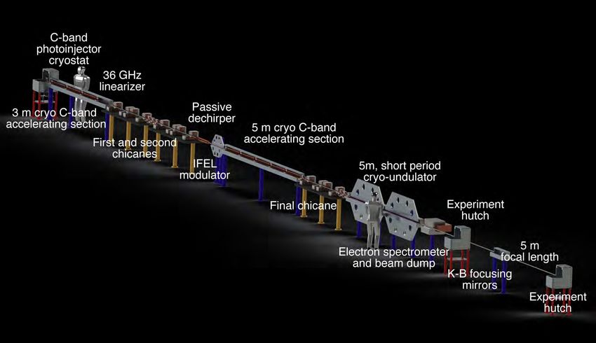
An Ultra-Compact X-Ray Free-Electron Laser                                                           2

              (UC-XFEL). In addition, one may accelerate these bright beams to GeV scale in less
              than 10 meters. Such an injector, when combined with inverse free electron laser-
              based bunching techniques can produce multi-kA beams with unprecedented beam
              quality, quantified by 50 nm-rad normalized emittances. The emittance, we note is
              the effective area in transverse phase space ((x, px /me c) or (y, py /me c) occupied by
              the beam distribution, and it is relevant to achievable beam sizes as well as setting
              a limit on FEL wavelength, as discussed below. These beams, when injected into
              innovative, short-period (1-10 mm) undulators uniquely enable UC-XFELs having
              footprints consistent with university-scale laboratories. We describe the architecture
              and predicted performance of this novel light source, which promises photon production
              per pulse of a few percent of existing XFEL sources. We review implementation issues
              including collective beam effects, compact x-ray optics systems, and other relevant
              technical challenges. To illustrate the potential of such a light source to fundamentally
              change the current paradigm of XFELs with their limited access, we examine possible
              applications in biology, chemistry, materials, atomic physics, industry, and medicine
              – including the imaging of virus particles – which may profit from this new model of
              performing XFEL science.

Keywords: free-electron laser, high accelerating gradient, cryogenic RF, IFEL, high
brightness beams

1. Introduction

The x-ray free electron laser (XFEL) is a transformative instrument, producing coherent
x-ray pulses with peak brightness 10 orders of magnitude greater than preceding
approaches [1]. The existence of a coherent Å-wavelength source with femtosecond
pulses has changed the landscape of science. After only a decade of operation of
the first hard x-ray FEL, the LCLS at SLAC, its unprecedented source parameters
and associated instruments have combined to form an invaluable tool for research
in chemistry, biology, materials science, medicine, and physics [2]. As such, XFELs
are laboratories with an inherent and deep multi-disciplinary flavor. The LCLS and
the other hard x-ray FELs [3, 4] worldwide are based on two enabling technologies:
conventional or superconducting RF accelerating structures and magnetic undulators
with periods of at least 1.5 cm. These each contribute to the footprint ( km scale, with
the smallest instruments near 0.7 km in length) and cost of recent generation XFELs.
This combination of unique research significance and high cost means user demand
significantly outstrips supply. As a concrete example there exists only a single XFEL
facility in the US, the LCLS, which is able to satisfy the beam-time requests of less
than 20 percent of the proposed experiments. The types of science that can be engaged
in this constrained model are limited there can be little cross-checking and iteration
based on empirical feedback. There are also few opportunities for translational research
in industry, medicine and other applied fields. Smaller, less expensive XFELs have
been built with more constrained X-ray production. To illustrate this point, we look to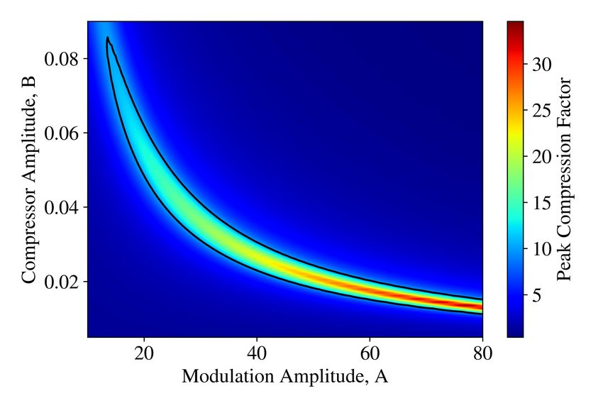
An Ultra-Compact X-Ray Free-Electron Laser                                              3

two examples, SwissFEL and SACLA, with their shared emphasis on high brightness
electron beams and high gradient acceleration techniques. They have footprints of 550
m and 600 m in total length, and comprehensive total costs of approximately 400 million
dollars.
     The current generation of XFELs has greatly exceeded performance expectations.
The progressive successes of XFELs has made a case that next-generation XFELs are
essential. This interest in expansion is manifested in the soft x-ray regime by LCLS-II
[5], a billion-dollar-class facility aimed at exploitation of coherent, ultra-fast photons
at longer wavelength, where new opportunities in spectroscopy await. There is also
compelling interest in harder x-rays, above 40 keV, to perform imaging in dense, high-
Z, mesoscale systems, such as the MaRIE XFEL proposed at LANL [6, 7, 8].
     While x-ray free-electron lasers have attracted multiple billions of dollars in
cumulative investment, they still number only a handful worldwide [9, 10, 11, 12, 13, 14].
Despite the scientific success and tremendous demand from the user community, the
XFEL in its present range of configurations, due to the expense and user limitations
involved, has stimulated competitive, alternative approaches to appear. These seek
to preserve the extraordinary flexibility and temporal advantages of an XFEL while
dramatically reducing the size and cost of the instrument. An XFEL that is both highly
capable and miniaturized has the power to resolve the issue of access that is currently
constraining scientific discovery. To develop an ultra-compact XFEL, however, one must
reinvent the approach to creating x-rays using the free-electron laser mechanism. Given
this history and current status, it is notable that the birth of the XFEL was based
on proof-of-principle physics experiments in previous decades that were carried out by
small research teams working in an innovative, exploratory fashion [15]. To reinvent the
XFEL we seek to profit from the same approach.
     Previous proposals on realizing very compact XFELs have concentrated on the use
of advanced accelerator techniques [16, 17] to minimize the length of the accelerator,
thus achieving 10 GeV-level beams in a length in the 10s of meter range or below. This
class of instrument is seen as a step beyond the XFEL, which is termed a 4th generation
light source – thus the miniaturization of the XFEL with an advanced accelerator is
termed a 5th generation light source. These proposals, at present emphasizing a range
of techniques from existing high gradient radio-frequency linear accelerators (linacs), to
plasma-based acceleration, have not profited from potentially transformative changes in
magnetic undulator design. As we shall see in the following, this is due, particularly
in the case of plasma acceleration, to the lack of advances in beam quality needed to
use accelerators with lower energy, employed in tandem with advanced, short-period
undulator methods.
     In this paper, we will present the details of a new approach that exploits multiple
scientific advances to realize the design of an ultra-compact XFEL (UC-XFEL). We
emphasize first the fundamental performance aspects of the XFEL, to ascertain the
approach to an optimized design. Instead of adapting the FEL to the acceleration
technique used, we employ a comprehensive design philosophy that is derived from
An Ultra-Compact X-Ray Free-Electron Laser                                                4

simultaneously examining multiple aspects of the FEL system. Given the decade
of dedicated research relevant to components of the 5th generation light source, this
integrated approach can now be crystallized; the concept for an ultra-compact x-ray FEL
presented here utilizes a recipe based on dramatic advances in the critical component
ingredients of the FEL, with the key aspect being the use of an electron beam with
unprecedentedly high six-dimensional brightness.
     On this basis, we propose here a new class of UC-XFEL sources that can be
implemented at the university level, at size and cost diminished more than ten-fold.
Despite this down-scaling, we project that this type of UC-XFEL may produce photon
fluxes per pulse that yield several percent of existing full-scale XFELs, in both the soft
and hard x-ray regions. This model of affordable, distributed x-ray lasers will make
intense, coherent, ultra-fast sources available to the broad scientific community in a
ubiquitous way, similar to the optical lasers now employed at university labs in many
diverse fields. Present XFEL experiments, by their nature, have a certain metric for
success, which is found in producing one-of-a-kind results in a short period of running
on the scale of days. Relaxing this constraint will inevitably lead to new scientific
results, much like the explosion of scientific activity in the early days of synchrotron
radiation sources, with the subsequent, rapid development of hundreds of beamlines
worldwide [18]. It is similarly envisioned that the UC-XFEL, which has a predicted cost
that is similarly less than five percent of existing XFELs, will permit wide availability
of coherent x-rays to a significantly broadened user community.
     We discuss below a recipe for taking the km-scale XFEL and miniaturizing it to fit
inside the footprint of a university building. To inform the discussion that follows, and to
aid in visualization, we show in Figure 1 a conceptual layout of the UC-XFEL, including
its major components at scale. It can be appreciated that the total longitudinal footprint
of the instrument is below 50 m. The rationale for the choices made in the UC-XFEL
are motivated in what follows. The discussion in this paper is quite detailed, examining
many advanced aspects of the UC-XFEL’s physical and technological properties. The
depth of this discussion is demanded by the challenging nature of the cutting edge
techniques proposed for use, and by the intricate physical coupling of various subsystems
in the UC-XFEL. Critically, this detailed discussion shows how it is possible to balance
the myriad of advantages and limitations attendant with the suite of advanced methods
employed, and mesh them together into a high-performing, functioning whole. Through
this discussion it is shown that a highly credible path to realizing this paradigm-changing
instrument, the ultra-compact x-ray free-electron laser, exists.
An Ultra-Compact X-Ray Free-Electron Laser                                                5

              Figure 1. To-scale conceptual layout of the soft x-ray (SXR) UC-XFEL, marking
              major component systems, with an end-to-end length of approximately 40 meters.
              Human figures shown for size comparison.

2. A Recipe for an Ultra-Compact XFEL

As noted above, there has been considerable existing effort aimed at imagining, in detail,
an ultra-compact XFEL, without definitive result. To shed light on this challenge, we
review a number of relations that one should introduce to quantify the task of realizing
the UC-XFEL. The most important gives the dependence of the resonant, on-axis lasing
wavelength, λr , on the beam and magnetic undulator parameters:

                                      λu        1 2
                                λr = 2 1 + Ku .                                       (1)
                                     2γ         2
Here γ = Ue /me c2 is the beam energy, Ue , normalized to the rest energy, me c2 , and the
planar undulator parameter

                                            eB0
                                      Ku =         ,                               (2)
                                           ku me c
where the magnetic field in the undulator’s symmetry plane is taken to be of the form

                                    By = B0 cos(ku z).                                  (3)
An Ultra-Compact X-Ray Free-Electron Laser 6
For present-day undulators, with period λu = 2π/ku of a few cm, the parameter Ku
slightly exceeds unity in most devices. The physical significance of Ku is that it indicates
the vector potential amplitude, normalized to the measure of relativistic momentum,
me c. Further, one may note that it measures the coupling of the electromagnetic wave
in the FEL to the electron’s undulating motion, as the maximum angle found in the
oscillating design trajectory is θmax = Ku /γ. This angle reflects the degree with which
the electrons can exchange energy with the FEL light.
The present authors have examined in some detail the mitigation of beam energy
demands in the XFEL through a significant shortening of the undulator period from
λu,> to λu,< , to the millimeter level or below [19]. This period-shortening has the effect
of reducing the beam energy demanded, γ< , from a reference design, γ> , by a factor
s
λu,< 1 + 12 Ku,<
2
γ<
Rγ = = . (4)
γ> λu,> 1 + 12 Ku,>
2
With peak fields B0 near the 1 T level, scaling to mm-period reduces Ku,< to below
unity. This reduction factor in the beam energy demanded is significant;q in the limit
λu,>
of small (relative to unity) Ku,< and large Ku,> it is approximately K . It
2λu,< u,>
is clear from this relation that one may decrease the energy needs of the FEL in this
manner by as much as an order of magnitude, dependent on the details of the undulator
parameters chosen. We will in this paper discuss various options for employing short-
period undulators, and progress in their realization. The examples chosen will have
energies in the 1 to 1.6 GeV range, to be compared with 4.3 GeV and 5.8 GeV in the
cases of LCLS-II and SwissFEL [12], respectively.
We note that the use of shorter undulator period also inherently shortens the
undulator length required to achieve FEL saturation. This is explicitly seen through
the expression for the exponential gain length of the FEL instability [20],
λu
Lg = √ . (5)
4π 3ρ
In a single pass, unseeded XFEL which relies self-amplification of spontaneous emission
(SASE), this instability typically proceeds to saturation within 20Lg , indicating that
the undulator length is shortened proportionally to λu , without consideration of the
variation of other parameters. This expression also introduces the Pierce (dimensionless
gain) parameter, given by
I γKu2 [JJ]2 (Ku2 )
ρ3 = , (6)
4IA (1 + Ku2 /2)2 (kr σx )2
where [JJ]2 (Ku2 ) is a Bessel-function dependent parameter that is near unity for Ku2 < 1,
I is the beam current, IA is the Alfvén current, IA = ec/re ≈ 17.045 kA, where re is the
classical electron radius, kr = 2π/λr and the transverse beam rms spot size is σx . It can
be seen that ρ3 ∝ I/σx2 , the beam current density. Its maximization, or alternatively the
minimization of the gain length, is accomplished through high current (kA-level), smallAn Ultra-Compact X-Ray Free-Electron Laser 7
emittance, n (i.e. the rms size of the beam distribution in transverse phase space), and
tight focusing of the beam. It is often stated that the ρ3 is proportional to the five-
dimensional beam electron brightness, B5D ≡ 2I/2n . We will, in the following section,
give a more direct, quantified analysis of the dependence of the gain parameter on beam
quality, using the six-dimensional beam brightness
2I
B6D ≡ , (7)
2n σγ
where σγ = σUe /me c2 is the electron beam’s normalized rms energy spread. We note
that this energy spread also is directly related to ρ, in that we require σγ /γ < ρ in order
achieve lasing – larger energy spreads cause Landau damping to extinguish the FEL
instability. Further, one may relate the efficiency of beam energy extraction to FEL
radiation with the Pierce parameter, ηFEL = Nγ h̄ωr /Nb Ue ' ρ.
One may also note that the gain parameter is dependent on the efficacy of the
focusing applied to the beam. Innovative approaches to this focusing, using advanced
high field quadrupoles, may be needed to provide an optimal spot size σx ; these methods
are discussed below. This spot size is limited from below by betatron motion induced
slippage and diffraction effects, which require that the radiation Rayleigh range as
approximated by Zr = 4πσx2 /λr is notably larger than Lg . For XFELs, this effect is
often ignorable due to the short wavelength of the lasing photons. Finally, the emittance
should also be small to obey the coherence requirement termed the Pellegrini criterion,
n < γλr /4π, which guarantees the overlap of the radiation of individual electrons in the
beam with each other to coherently add and create the lasing mode [21]. Quantitatively,
as we are attempting to strongly lower the beam energy by the use of short-period
undulators, a very low normalized emittance is demanded.
Much recent progress has been made in understanding how to improve the emittance
and attendant brightness of electron beams. The introduction of the high field RF
photoinjector approximately 30 years ago [22] was a critical step forward in this regard,
an advance that yielded an order of magnitude increase in beam brightness. This
improvement, which was based on the use of large accelerating fields and optimized
beam optics (emittance compensation) techniques was a key element in the realization
of the SASE FEL [23]. Recently, it has been shown by a SLAC-UCLA collaboration that
one may strongly increase the peak operating surface field in copper RF cavities from the
nominal current value of E0 =120 MV/m by a factor of up to four. This is accomplished
by cryogenically cooling the copper, to enter into the anomalous skin effect (ASE) regime
[24]. The combination of resulting lower dissipation due to diminished surface resistivity
with increased material yield strength and mitigation of thermal expansion are the
physical effects underpinning this remarkable advance. Applying increased fields in the
photoinjector should have profound implications for beam brightness, which stands to
be increased 50-fold over the original LCLS design [25, 26, 27], and similarly advance
the recent state-of-the-art [28]. We discuss the expected performance of such a high field
photoinjector, operated at E0 = 240 MV/m below, and deepen previous discussions toAn Ultra-Compact X-Ray Free-Electron Laser 8
examine the implications of more advanced RF designs.
This new approach to high field RF acceleration also permits a dramatic reduction
in length of the accelerator needed for the UC-XFEL. A cryogenically-cooled C-band
linear accelerator structure is now being developed for linear collider applications at
SLAC and UCLA [25, 26], with operation at an average accelerating gradient of
eEacc = 125 MeV/m; this entails using a peak surface field of 250 MV/m, nearly
identical to that found in the photoinjector. To put this gradient in perspective, it is
over a factor of six larger than that employed at LCLS [3] and LCLS-II. To reach Ue =1
GeV (for our soft x-ray example) one would need eight meters of active length with this
approach. Between the reduction in energy needed and enhanced gradient employed,
the accelerator is shortened by a factor of over 25. The proposed accelerator sections are
of an innovative design where the coupling is achieved independently through a wave-
guide manifold; there is negligible cell-to-cell coupling in this standing wave design. As
such, the accelerating structure may be optimized to have a very high power efficiency
[29], as measured by the shunt impedance.
The approach described above yields, in simulation, a beam from the photoinjector
having 20 A peak current and n ' 50 nm-rad. This extremely low emittance must
be preserved during both high field acceleration and pulse compression, which entails
enhancing the current to several kA to achieve strong XFEL gain. We explore this
process in detail, identifying a compact (total lengthAn Ultra-Compact X-Ray Free-Electron Laser 9
design is therefore attractive in our case.
With the above-listed ingredients, a beam capable of using 1 to 10 mm period
undulators, reaching hard and soft x-ray FEL operation, may be envisioned. In this
context, we discuss the present state-of-the-art in sub-cm period undulators, and identify
paths to extend current designs (existing down to λu = 7 mm) to the 1 mm level. We
show through start-to-end simulation analysis, that the saturation length for producing
multi-10’s of gigawatt XFEL power is 4 m at 1 nm, and 6 m at 1.5 Å operation,
respectively. The per-pulse photon flux predicted is nearly five percent of current LCLS
operations, in an instrument with a total footprint below 30 m in length.
Such a compact system demands, for consistency, x-ray optics and experimental end
stations which are scaled down in size in a similar fashion, to less than 10 m in length.
We discuss approaches to such optics which take advantage of several notable differences
between the UC-XFEL and current generation full-scale XFELs: the reduction in peak
power and integrated fluence, and increased divergence in the radiation. This analysis
is informed by a discussion of a variety of experimental opportunities opened by the
realization of an ultra-compact XFEL based on these emergent technologies discussed
above, and associated advances in physics design principles.
3. Six-dimensional Brightness Scaling in SASE FELs
While the recipe introduced above explains the conceptual dependencies connecting the
suite of ideas introduced that enable the UC-XFEL, it is more direct and intuitive to
describe the XFEL in the order in which the electron beam encounters the component
systems. This begins with the electron source, which plays a central role in enabling
the needed performance of the UC-XFEL.
Arguments in favor of the advantages of high brightness beams for driving SASE
FELs have traditionally been based on the 5D brightness, B5D . This viewpoint is
problematic, however, as B5D is not a conserved quantity. On the other hand, the
Liouville theorem indicates that the six-dimensional brightness B6D is conserved in a
local sense. We thus present here an analysis of the Pierce gain parameter, ρ, that
seeks to reveal its dependence on B6D . Here we assume that there are no correlations
in the 6D phase space after the beam is prepared for lasing, and that dilution of B6D (a
measure based on rms quantities) may be ignored.
We begin by noting that for values of the undulator strength parameter Ku < 1 as
encountered in the UC-XFEL, the expression for the Pierce parameter can be simplified
to read approximately
I γKu2
ρ3 ' . (8)
4IA kr2 σx2
We have written ρ in terms of the radiation wave-number, as we will aim to reveal
scaling of parameters while holding the FEL wavelength fixed.
To relate the gain to the beam brightness, we first write the emittance in termsAn Ultra-Compact X-Ray Free-Electron Laser 10
of the Pellegrini criterion x ' n /γ = η /2kr , i.e., where η is less than or equal to
unity. When it takes the value 1, the electron and photon beam emittances are equal.
Additionally, we will assume the peak undulator fields to be fixed by design limits at
B0 ' 1 T and thereby rewrite the undulator parameter in the following way,
eB0 1 2γ 2
Ku = ≡ = , (9)
ku me c ku rB rB kr
where the parameter rB = 1.7 mm can be understood as the radius of curvature of
the trajectory an electron having momentum me c follows in a uniform field of strength
1 T. In the last equality we have approximated the FEL resonance condition valid to
lowest-order in Ku , ku = kr /2γ 2 .
To optimize the focusing of the electron beam, we additionally take the average
Twiss β-function of the electron beam to be near to the FEL gain length,
Lg 1
βx = = √ (10)
ηβ 2ηβ ku 3ρ
where we have introduced another factor, ηβ . This tuning factor is near to, but generally
slightly smaller than unity, depending on final FEL optimization. This scaling is due
to the need to avoid excessive transverse angles in the beam. We insert these scaling
relations into the expression for ρ3 , thus eliminating one power of ρ,
√ 5
√
3 2I η ηβ γ 3 η ηβ γ 5
ρ2 = 2 4
= B5D 2 4
. (11)
4IA 2n rB kr 4IA rB kr
In this last equality the 5D brightness is used. We now pass to a description of the scaling
which employs the six-dimensional rms brightness which, in the absence of transverse
and longitudinal emittance growth or beam loss, may be conserved. We relate the 5D
and 6D brightness by introducing the normalized rms energy spread σγ , and indicate
the familiar energy spread requirement as
σγ
= ηγ ρ, (12)
γ
where ηγ is another optimization factor, similarly limited above by unity. In this case
we can rewrite the expression for ρ utilize the 6D beam brightness,
B6D = B5D /σγ (13)
to obtain √
3 η ηβ ηγ γ 6
ρ= 2 4
B6D . (14)
4IA rB kr
From this analysis we see that the Pierce parameter, which dictates the gain length
and efficiency characteristics of the XFEL, has linear scaling with the six-dimensional
electron beam brightness. This is much more striking than the commonly quoted
1/3
dependence on 5D brightness ρ ∝ B5D . The scaling with energy also appears asAn Ultra-Compact X-Ray Free-Electron Laser 11
quite strong, depending as γ 6 . Conversely, if one includes the implicit variation of
kr (γ), holding the undulator period constant (as is more often the case in FEL design
strategies), this reverses, and ρ ∝ γ −2 . However, in the UC-XFEL, we are concerned
with achieving a certain kr = 2π/λr through increasing ku and thus using smaller γ.
This strong energy dependence indicates that we must, in order to operate at smaller γ,
dramatically increase the electron beam 6D brightness. The approach to the electron
source yielding this critical advance is discussed in the next section.
Before introducing the approach to the initial production of high beam brightness,
we note that the factors η , ηβ ,and ηγ can be analyzed with sophisticated optimization
procedures. These procedures are aided by theoretical work that has been based, as
is presented here, on an analysis based on 6D brightness [37]. Similarly, design trade-
offs are necessary to include the effects of non-one-dimensional phenomena such as
diffraction. This type of optimization has been studied in the context of the well-known
Xie analysis, found in Refs. [38, 39], and extended to include space-charge in Ref. [40].
4. High Gradient Cryogenic Photoinjector
The approach to photoinjector for UC-XFEL has been chosen by extending several
previous studies of the potential use of cryogenic cooling of the RF cavities [25, 26].
These studies, along with experimental investigations of the breakdown and dark-
current emission performance of cryogenic cavities [41], have yielded in previous work
an optimized surface electric field on the photocathode E0 = 240 MV/m. This field,
obtained in a high shunt-impedance RF structure geometry, is a factor of two below the
measured breakdown limit in cryogenic copper [42], and also well below the threshold
(300 MV/m) of large dark current emission. The novel shape of the structure, inspired
by the optimized linear accelerator structure discussed in the next section, is indicated
in Figure 2. Even with derating of the maximum field, the brightness obtained by this
new generation of RF photoinjector should significantly increase over current values.
This is due to, above all, the increased beam density at emission. As discussed in
Ref. [26], the five-dimensional brightness is expected to scale as B5D ∝ Ein , where Ei
is the amplitude of the initial launch field, and the exponent n is between 1.5 and 2,
depending on the beam shape. In the regime where we intend to operate, n ' 1.5. The
six-dimensional brightness, including the effect of space-charge on slice energy spread
(∝ Ei−0.5 ) [43, 44, 45], the scales as B6D ∝ Ei2 . The proposed high field cryogenic C-
band RF photoinjector source takes advantage of this scaling. We will see that this step
forward must also be accompanied by innovative approaches to brightness preservation
during beam manipulations after the injector.
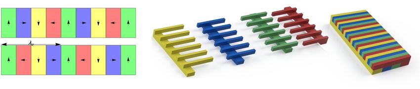
As illustrated, the proposed photoinjector RF structure is a 1.6 cell C-band gun
with an optimized shape that minimizes the magnetic field on the surfaces. This is a
new geometry, with many different features from previously studied photoinjectors [25].
The chosen form of the cavity, having pronounced re-entrant irises, permits lower input
power and mitigates dissipation at cryogenic temperatures. With an expected overallAn Ultra-Compact X-Ray Free-Electron Laser 12
Figure 2. Geometry of 1.6 cell C-band cryogenic photoinjector, without coupling.
Overlaid with the longitudinal electric field, illustrating significant higher spatial
harmonics.
repetition rate of 100 Hz, and nominal 300 nsec RF pulses, at the foreseen operating
temperature of 27 K this dissipation is 11 W, requiring over 0.5 kW cooling power. This
operating point is chosen, in part, to take advantage of the faster response times and
associated mitigation of power considerations in the UC-XFEL, as well as its possible
utility for application in the MaRIE XFEL.
This optimized RF structure has several potentially important impacts on the
performance of the photo-emitted beam. The significant higher spatial harmonic content
(see Figure 2) in the RF profile arising from optimizing the shunt impedance (to over
400 MΩ/m) through re-entrant features provides a beneficial effect: enhancement of
the second-order RF transverse focusing experienced by the electrons [46]. These
spatial harmonics may also introduce a nonlinear radial dependence of the focusing andAn Ultra-Compact X-Ray Free-Electron Laser 13
Parameter Units Value
π-mode cells − 1.6
Peak axial field, E0 MV/m 240
Charge per pulse pC 100
Peak solenoid field, Bpeak T 0.55
Spot size on cathode, σx µm 75
Thermal emittance at cathode nm-rad 38
Pulse length psec 5
Energy after acceleration MeV 153
Final normalized emittance, n nm-rad 55
Table 1. Parameters of the ultra-high brightness RF photoinjector for UC-XFEL used
in GPT simulation.
defocusing fields in the gun cavity which could, for beams with non-trivial radial extent,
lead to rms emittance growth. This has been found to not be the case for the parameters
of the UC-XFEL photoinjector. This has been shown through simulations in which the
full, nonlinear, 3D form of the transverse fields are used. They are observed to differ
from those where the fields are are linearly extrapolated off-axis from the on-axis field
behavior in producing emittances which increase by no more than one nanometer-radian.
In this regard, we note that beam dynamics simulations of the injector using the code
GPT [47] include modeling of the following physical effects: cathode emission properties;
3D electromagnetic fields; 2D solenoid fields; and space-charge forces (including image-
derived) obtained from placing the charge and current on a 3D grid. The effects of
intra-beam scattering (IBS) are included in an analytical estimate discussed below.
Figure 3. Emittance evolution from a C-band cryogenic RF photoinjector, with final
value reaching n = 55 nm-rad.An Ultra-Compact X-Ray Free-Electron Laser 14
These effects have thus been studied along with the overall performance of the
photoinjector, and found to yield beam brightness further enhanced over that reported
in Ref. [25]. This study includes solenoid focusing similar to that of a scaled LCLS
gun with a 1.05 meter drift to the first post-acceleration linac (described in the next
section). Designs of a newly-conceived compact, cryogenic high field (Bpeak =0.55 T)
solenoid have been employed in the beam dynamics simulations. Results from these
studies include the evolution of the rms emittance and beam size during the focusing
and accelerating process, yielding emittance compensation, as shown in Figure 3. The
final emittance after acceleration to Ue = 153 MeV is excellent: n = 55 nm-rad (at
z = 4.4 m). This is achieved with Qb =100 pC charge, and 5 psec FWHM pulse length,
with peak current Ip = 20 A. As we shall see, this value of emittance is near to the
value which can be preserved in accelerating, transporting, and compressing the beam
to its final current of 4 kA. As we are interested in the 6D brightness of the source,
which is at best preserved in acceleration and transport, it is important to evaluate
the longitudinal slice energy spread which, after including IBS, is near 1.6 keV. In this
case, the achieved 6D brightness is B6D = 5 × 10¹⁸ A/(m-rad)2 . This can be compared
to the value associated with the LCLS design, at B6D = 5.1 × 10¹⁶ A/(m-rad)2 , which
is two orders of magnitude smaller. Advances in 6D brightness have been noted since
the LCLS design was introduced; recent experiments in generating very low emittance
beams at SwissFEL have given a 6D source brightness of 5.5 × 10¹⁷ A/(m-rad)2 [28].
Thus there is an order of magnitude improvement of the high field cryogenic source in
this parameterization of beam quality over a current state-of-the-art value.
The characteristics of the beam longitudinal phase space at the injector exit are
shown in the GPT simulation results displayed in Figure 4. Use of a stronger solenoid
(0.64 T) can result in a beam with lower emittance, (n = 50 nm-rad) through control of
the transverse beam oscillation amplitudes. The decrease in beam size, however, yields
some pulse length expansion from longitudinal space-charge effects, to 6.2 psec. For the
remainder of this paper, we utilize the shorter beam option, as it stresses the sensitive
downstream compression processes less.
We note that the beam dynamics and emittance compensation process have been
optimized in this case considering a copper photocathode with nominal “thermal” rms
normalized emittance [48] given by 0.5 mm-mrad/mm [49]. This can be improved
upon in principle by using advanced methods involving novel cathode materials, or by
taking advantage of the cryogenic state of the emitting surface [50]. This approach
permits the maintenance of a small emittance at larger emitting spot sizes, while
giving shorter pulses and higher peak current. Studies of this optimization path in
the zero-thermal-emittance limit have shown notably higher brightness [51]. While
this potentially advantageous approach remains under study (in simulation [51] and in
current experiments at UCLA), the predicted performance of the UC-XFEL as presented
here does not depend on its implementation. In this regard, it should be stated that
introduction of novel photo-cathodes would also have an effect on the challenge of
operating in a large field-emission (dark current) environment [41], which remains a keyAn Ultra-Compact X-Ray Free-Electron Laser 15
153.6 20.0 1.0
153.4 0.9
153.2 15.0 0.8
Energy Spread (keV)
Energy (MeV)
153.0 0.7
Current (A)
152.8 10.0 0.6
152.6 0.5
152.4 5.0 0.4
152.2 0.3
152.0 -1.0 -0.5 0.0 0.5 1.0 0.0 -1.0 -0.5 0.0 0.5 1.00.2
Longitudinal Position (mm) Longitudinal Position (mm)
Figure 4. (Left) Longitudinal phase space at the exit of the photoinjector and (right)
plots of the current profile and slice energy spread. The beam head is to the right.
issue in the experimental realization of this high field, high brightness photoinjector.
Similarly, potential problems in managing emission characteristics are found in a large
laser fluence environment [52], as may be necessary in the high-field photoinjector, with
its emphasis on small emitting areas.
The photoinjector system functionally consists of the very high field RF gun,
focusing optics, and post-acceleration cryogenic linacs operated at an average
acceleration gradient of 125 MeV/m. A first version of both the cryogenic C-band
RF gun and linear accelerator (linac) structures are now under development by a
UCLA-Stanford-LANL-INFN collaboration, with an initial emphasis on linear collider
applications [53]. In the experimental work relevant to linear colliders, the RF gun
beam dynamics concentrate on the case of a magnetized photocathode, which is used
with skew quadrupoles after post-acceleration in the linac to produce highly asymmetric
emittances after removal of the angular momentum in the beam [54]. The symmetric,
unmagnetized beam case relevant to UC-XFEL is also to be examined using the same
experimental infrastructure. The design of the linac structure used in these experiments,
and in the UC-XFEL, are described in the next section.
5. Linear Accelerating Structure
The linac structures proposed for the UC-XFEL, as noted, also rely on use of cryogenic
C-band copper cavities. Their design is based on a similar philosophy as the RF gun
cavities, with a highly optimized shape. At cryogenic temperatures, this optimized
structure yields a shunt impedance of 460 MΩ/m. This quite high value is obtained by
eliminating cell-to-cell coupling through the irises, in favor of a re-entrant geometry. In
applications such as the linear collider or XFEL, this geometry has notable advantages
over previous generations of X-band linacs, where such a re-entrant structure would
provoke transverse wakefields that are very challenging to manage. As the re-entrant
design isolates each cavity, the linac section design thus exploits a new coupling scheme,An Ultra-Compact X-Ray Free-Electron Laser 16
with independent coupling from a wave-guide manifold to each individual cell [29]. The
resulting form of the linac structure is shown in Figure 5.
Figure 5. Rendering of 40-cellcryogenic copper linear accelerator structure, with
individual cell coupling from wave-guide manifold.
These structures are now under development and initial testing at SLAC and
UCLA. The initial goal of these studies is the investigation, introduced above, into
the production of linear collider-quality, asymmetric emittance beams through the
use of a magnetized photocathode [54], and the demonstration of subsequent high
gradient acceleration, at both 27 K and 77 K operating temperatures. While the
design and innovative realization of these cryogenic structures is rapidly maturing, there
are compelling issues left to address. Prominent among these topics is the control
of transverse field effects, including multi-bunch beam break-up (BBU), through the
damping of higher order modes (HOM) [55, 56]. Simulation and optimization studies
are now underway to consider the addition of mode damping and frequency detuning
to address BBU in this novel geometry. Experimentally, peak accelerating gradients of
up to 140 MeV/m, consistent with the design parameters demanded here, have been
demonstrated in X-band linac prototypes based on this design [29]. It should also be
noted that multi-cell cryogenic copper accelerating sections are now being fabricated
by creating two pieces split along the midplane, and then joining these pieces using
innovative techniques such as electron-beam welding. In such a way, one may create
intricately shaped cavities for optimizing the shunt impedance, as well as HOM damping,
effectively and at lower cost.
One of the essential advantages of using high gradient cryogenic RF linacs is to yield
acceleration giving the beam energy needed for UC-XFEL on a 10 m length scale. This
serves the goal of making a compact system in its own right. The compactness of the
linac (as well as the unique approach to final beam compression) also yields a secondary,
but critically important advantage: it suppresses the micro-bunching instability (MBI).
As this instability is particularly worrisome for high brightness beams, its mitigation,
discussed further below, is essential for the UC-XFEL.
In the longer term, research and development into cryogenic RF acceleration has
other fundamental subjects to address. First, one should understand the dramatic
increase in breakdown fields in more detail, to push demonstrated, useful performance
of cryogenic RF cavities to >500 MV/m surface fields. To do so, it is essential to
understand the dynamics of surface breakdown, and field emission currents, as well as
their mitigation. These investigations have been initiated, and are enabled through a
first-principles simulation effort using molecular dynamics codes developed at LANL [57]An Ultra-Compact X-Ray Free-Electron Laser 17
for advanced materials investigations. These studies should permit an understanding of
the potential role of copper alloys and other materials in extending breakdown towards
the theoretical limit dictated by material stress. Further, the use of coatings such as
graphene and silicon oxynitride [58] is now under study for mitigation of field emission.
These efforts, while not critical to the vision of the UC-XFEL presented here, are
directed towards large long-term projects such as compact linear colliders [53, 59] and
next generation full-scale XFELs such as MaRIE [33].
5.1. Alternative Approaches for High Brightness Beam Production
The push towards an ultra-compact XFEL using advanced accelerators has taken
place predominantly in the context of plasma accelerators. Particularly, laser-plasma
accelerators (LPAs) that can produce, by injection of electrons from the background
plasma, a beam that is accelerated up to multi-GeV [60] energies in a few cm distance,
are very attractive to apply in the XFEL context. Indeed, due to this fortuitous energy
reach, LPAs have been vigorously examined as candidates for ultra-compact FELs [61].
Further, the beams produced by LPAs possess parameters that are competitive with
certain classes of present day injectors. As such, much research has been focused recently
on radiation production by LPA-produced beams, not only from FELs [62, 63], but also
including hard photon emission from Compton scattering sources [64], and from betatron
radiation [65].
Progress, despite notable efforts, has been incremental in the field of LPA-based
XFELs. As a concrete example of the level of beam quality presently achievable by LPAs,
consider the parameters reported in Ref. [66], which explicitly cites the 6D brightness
achieved. It is given, in the units of this current paper, by B6D ' 1 × 10¹⁵ A/(m-rad)2 .
This is a surprisingly small value, but one must keep in mind that, for similar charge,
while the pulse length is notably shorter in the LPA, the beam emittance is an order
of magnitude larger, and energy spread exceeds that of the photoinjector by two orders
of magnitude. Thus one can see from the scaling given by Equation 14, that use of
lower energy beams and/or short FEL wavelengths will be very challenging with such
a source. Stated another way, the approach adopted here gives a much more robust
solution to the challenge of making a compact XFEL.
There are two possible paths forward in plasma-based XFELs that arise from
current research trends. The first is that one may utilize beams that are stretched
either transversely, using a transverse gradient undulator [67], or longitudinally through
a chicane transformation [68, 69], to mitigate the influence of energy spread on the gain
of the FEL. These approaches produce only modest advantages in the gain performance
of the FEL [70]. A more definitive solution is found in changing the approach to particle
injection, to emphasize the creation of a much higher 6D-brightness beam. For example,
one may employ the plasma photocathode (or “Trojan Horse”) ionization scheme, to
produce beams with much lower emittance, and improved energy spread [71]. Studies
have shown [72] that the 6D brightness obtained from this scheme is at the level ofAn Ultra-Compact X-Ray Free-Electron Laser 18
B6D ' 3.6 × 10¹⁸ A/(m-rad)2 . This value is superior to that found in the current case
of a high field cryogenic photoinjector, and points to the critical role of the injection
field; E0 ' 10 GV/m in this case, and very small source size. This promising approach
to very high brightness beam production is in its experimental infancy, with beams still
near in quality to the LPA-based injectors achieved in first tests [73].
One may also examine the possibility of using a high brightness beam obtained
from an RF photoinjector that is externally injected into a plasma accelerator. While
this solution is not as compact as a plasma-based injection scheme, with an optimized
approach to matching the beam transverse dynamics to the strong plasma focusing, the
brightness needed for driving an FEL may be reached. This is one of the central goals
of the EuPRAXIA project, which has reached the conceptual design phase [74]. This
external injection approach gives up the advantage of creating very high current beams
without compression. As we will see in the next section, this is a key challenge to be
confronted in the present UC-XFEL vision.
6. Electron Beam Acceleration and Compression
The electron beam is to be accelerated in the high gradient linac from 153 MeV (the
photoinjector exit) to the full 1 GeV (soft x-ray, or SXR, FEL) or 1.6 GeV energy (hard
x-ray, HXR, FEL) with two stages of compression taking the 20 A beams obtained from
the photoinjector to Ip = 4 kA. The first stage uses a standard chicane, albeit with
a higher harmonic RF linearization scheme [75, 76] operating in Ka -band [77]. The
need for such a high frequency device for linearization is widespread in the advanced
FEL field, and the dedicated development work is now being carried out at INFN-LNF
in the context of both this initiative and the XLS project [77]. The second stage of
compression employs inverse free-electron laser bunching, in a scheme known as ESASE
[31]. Throughout the beamline, both second-order RF focusing in the linacs [46] and
interspersed magnetic quadrupoles are used to control the beam envelope. We use 10 cm
length quadrupoles placed after each linac with gradients restricted to no more than 20
T/m. We discuss the physics performance of each of these steps below. This discussion is
guided by simulations of the beam performance using the beam dynamics code elegant
[78], using the beam produced by the photoinjector as input for the acceleration and
compression stages. The limitations of elegant in modelling 3D coherent synchrotron
radiation effects are explored using GPT, and found to introduce small, benign changes
in the beam dynamics. The photoinjector simulations were performed using 1.3 million
macroparticles. In moving this beam distribution to elegant, we employed the method
presented in Ref. [79] to estimate an increase in the uncorrelated energy spread of
1.5 keV in the photoinjector from IBS. This value adds in quadrature to the existing,
roughly 500 eV, uncorrelated spread produced by the injector simulations. Since this
value is an estimate and not the result of a rigorous simulation, we also discuss the
general impact of fluctuations in the energy spread on the machine design in Subsection
7.7. After numerically augmenting the energy spread to account for these effects, theAn Ultra-Compact X-Ray Free-Electron Laser 19
number of particles is increased to 34 million using the SDDS program smoothdist6s
to ensure proper modeling collective effects such as the microbunching instability. The
subsequent elegant simulations include the effects of longitudinal space charge in all
linac sections, a one-dimensional model of coherent synchrotron radiation (CSR) in
the bunch compressors, incoherent synchrotron radiation in the bunch compressors, and
intrabeam scattering (IBS) effects. To validate the use of the 1D CSR model, we present
the results of additional simulations of the bunch compressors performed using the 3D
CSR model employed in GPT [80].
6.1. Acceleration to the First Bunch Compressor
The first compression occurs at 400 MeV, an energy chosen to balance the competing
scaling of longitudinal space-charge and coherent synchrotron radiation (CSR). After
the gun, the beam is accelerated in three linac sections up to 416 MeV then slightly
decelerated in a sixth harmonic 34.272 GHz RF cavity [81] to 400 MeV to mitigate
the second-order variation in the beam longitudinal phase space due to RF and
wakefield effects. In this way, one may cancel the effects of the second-order momentum
compaction in the chicane. The sixth harmonic was chosen over a more conventional
11.424 GHz X-band cavity due to RF voltage considerations; the required energy drop
in the harmonic cavity scales with the inverse square of the harmonic number, resulting
in a needed > 100 MeV energy loss using 11.424 GHz. In addition to the increased
length of an X-band cavity relative to a 34 GHz cavity, this would necessitate use of an
additional meter long accelerating structure to maintain the 400 MeV working point.
In Table 2 we list the relevant parameters for the first linac section. This parameter set
represents a functional solution that allows us to preserve the 6D beam brightness well
in the subsequent compressor, but could potentially be further optimized to produce
an even more robust design. During this first acceleration stage the beam accumulates
approximately 200 eV of uncorrelated energy spread from IBS. This value has a small
effect on the optimization of the second linac. The relatively benign effect of IBS is again
owed to the limited interaction length implied by used of a compact, high gradient linac.
Parameter Units C-Band Linac Harmonic Cavity
Frequency GHz 5.712 34.272
Voltage change MeV 266.74 12.36
◦
Phase 75.91 -98.20
Table 2. Parameters for the first linac section and linearizing cavity.
6.2. Dynamics in the Compressor
In the interest of maintaining a compact design, only 5.5 m of the beamline is allocated
to the first compressor, termed BC1. Additionally, to preserve the beam’s 55 nm-rad
emittance as well as possible, we make use of two consecutive smaller chicanes with aAn Ultra-Compact X-Ray Free-Electron Laser 20
quadrupole triplet in the middle arrayed such that the second chicane mitigates the CSR
effects induced by the first chicane [82, 83]. The relevant parameters for the two chicanes
∂ζf
are reported in Table 3. The parameter R56 = ∂(δp/p 0)
is the momentum compaction,
i.e. the final final longitudinal position ζf to the initial fraction momentum deviation
from nominal δpi /p0 .
Parameter Units First Chicane Second Chicane
Magnet length m 0.2 0.2
Drift length m 1.29 0.21
◦
Bend angle 8.3 3.2
R56 mm 59.85 2.15
Entrance βx m 16.25 5.5
Entrance αx 4.1 3.1
Table 3. Parameters for the chicanes of the first bunch compressor.
The projected normalized emittance in elegant simulations grows to 80 nm-rad
after the first chicane but is brought back down to the 65 nm-rad level by the end of
the second. The projected emittance computed using only particles within the full-
width at half-maximum of the current distribution is yet smaller, at n = 60 nm-rad,
indicating only 5 nm-rad effective projected emittance growth in the region of interest.
As expected, the vertical emittance is largely unaffected by the compressor. The slice
emittance in both planes is nearly unchanged by the first bunch compressor, with all
growth resulting from misalignment of the x’ centroids of the longitudinal slices of the
beam.
406.0 600.0 60.0
404.0 500.0 50.0
Energy Spread (keV)
402.0 400.0 40.0
Energy (MeV)
Current (A)
400.0 300.0 30.0
398.0 200.0 20.0
396.0 100.0 10.0
394.0 -40.0 -20.0 0.0 20.0 40.0 0.0 -40.0 -20.0 0.0 20.0 40.0 0.0
Longitudinal Position (µm) Longitudinal Position (µm)
Figure 6. (Left) The longitudinal phase space of the beam after the first bunch
compressor is shown alongside (right) the current profile and slice energy spread. The
beam head is to the right.
To conclude the description of the first compressor we plot in Figure 6 the
longitudinal phase space, current, and energy spread profile of the beam immediatelyAn Ultra-Compact X-Ray Free-Electron Laser 21
following the chicane. There is a ∼45 µm longitudinal region in which the current
lies between 400 and 500 A. The current profile has developed two small peaks at
either end of the flat-top region which in a second bunch compressor might become
excessively large, provoking enhanced collective effects. We will find below that the
IFEL compressor is, however, insensitive to these peaks. The energy spread in the
flat-top region is approximately 34 keV; very little dilution of B6D is observed.
7. Second Bunch Compressor
Immediately following the first bunch compressor a passive dechirping cavity [84] is
employed to remove the remaining energy chirp from the beam. This device is a 1 m
long corrugated pipe structure with inner diameter of 0.77 mm and wall periodicity 0.2
mm. This may be substituted for a Cartesian structure, but the effect of quadrupole
field excitation on the emittance should then be evaluated. The dechirper is followed
by a quadrupole triplet for transverse matching into the modulator. The longitudinal
phase space following this dechirping cavity is shown in Figure 7.
Figure 7. The longitudinal phase space of the beam after dechirping after the first
compressor.
7.1. Overview of IFEL Compression
In order to mitigate as much as possible deleterious collective effects while reaching
a peak current of Ip = 4 kA, the second compressor does not employ an RF and
chicane-based transformation. Instead, it utilizes IFEL compression, introduced by
Zholents and also known as the method of enhanced self-amplified spontaneous emission
(ESASE) [31]. The conventional compressor approach would specifically introduce
several complications: first, as we explore further in the subsequent sections, one of
the primary advantages of using an ultra-high brightness beam is the ability to make
use of several-mm-period, small gap undulators. These undulators naturally reduce theAn Ultra-Compact X-Ray Free-Electron Laser 22
length of the system, but at the cost of enhanced resistive wall wakefields. Further,
a standard chicane compressor would demand a quite large momentum compaction at
the higher 1 GeV energy, which may lead to unmanageable slice emittance growth from
CSR. On the other hand, micro-bunched beams have been demonstrated to mitigate
resistive wall wakefield effects [33], and we confirm (and extend to a new conductivity
regime), and exploit this property in the sections that follow. Additionally, ESASE
allows 4 kA current to be achieved with only a mm-scale momentum compaction, as
we demonstrate below. This small momentum compaction entails notably less bending,
and the attendant challenges in brightness preservation due to CSR are significantly
reduced.
For an ESASE compressor scheme, one first modulates the electron beam energy
periodically in time using an infrared laser. The periodicity is imposed by the laser
wavelength, chosen in our first example as λL = 10 µm, which co-propagates with the
electron beam inside of a short planar undulator. Once this modulation is compressed
in a chicane, the beam is micro-bunched into a train of current spikes, each of which
lases independently of the others in the final undulator. We describe the process using
a sequence of two transformations. Let p = (γ − γ0 )/σγ and θ = kL s where γ0 is the
mean beam energy, σγ is the initial uncorrelated beam energy spread, and kL = 2π/λL .
Then the ESASE process is described by
p1 = p0 + A sin(θ0 ) (15)
θ2 = θ1 + Bp1 (16)
where A = ∆γL /σγ is the modulation amplitude normalized to the uncorrelated
energy spread and B = R56 kL σγ /γ0 is the normalized compression strength. The final
longitudinal particle coordinates are then related to the initial coordinates by
pf = pi + A sin(θi ) (17)
θf = θi + Bpi + AB sin(θi ) (18)
The resulting periodic current profile can be written [31, 33, 85]
∞
!
−n2 B 2 /2
X
I(θ) = I0 1+2 Jn (−nAB)e cos(nθ) , (19)
n=1
where Jn is the nth-order Bessel function of the first kind.
7.2. Choice of Operating Parameters
In the specific case that the ESASE IFEL system replaces a full bunch compressor, it
is designed to achieve four goals: optimization of the peak current at a specified value,
maximization of the micro-bunch full-width at half-maximum (FWHM) length, and
minimization of both the slice energy spread and slice emittance. In general, for a givenYou can also read