NZ Wood Design Guides - POST AND BEAM TIMBER CONSTRUCTION Chapter 9.5 | June 2020
←
→
Page content transcription
If your browser does not render page correctly, please read the page content below

NZ Wood Design Guides

     POST AND BEAM TIMBER CONSTRUCTION
                           Chapter 9.5 | June 2020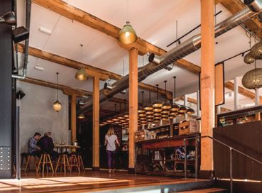
NZ Wood Design Guides is a Wood Processors and Manufacturers (WPMA) initiative
                                           designed to provide independent, non-proprietary information about timber and
                                           wood products to professionals and companies involved in building design and
                                           construction.
NZ Wood Design
Guides                                     ACKNOWLEDGEMENTS
A growing suite of information,
technical and training resources, the      Authors:  Lisa Oliver – Holmes Consulting
Design Guides have been created
to support the use of wood in the                    Ben White – Holmes Consulting
design and construction of the built       WORKING GROUP
environment.
                                           Tobias Smith – PTL I Structural Consultants
Each title has been written by experts     Andrew Dunbar – Structex
in the field and is the accumulated
result of years of experience in working
                                           CONTRIBUTORS
with wood and wood products.               Ben Karalus                  – Holmes Consulting
                                           Yal-el van der Westhuizen    – Holmes Consulting
                                           Luke Williams                – Holmes Solutions
Some of the popular topics covered         Eric McDonnell               – Holmes Structures
by the Design Guides include:
                                           Holmes Consulting for 3D images
● Timber, Carbon and the
  Environment                              NZ WOOD DESIGN GUIDE SUPPORT GROUP
● Seismic Design                           WPMA Project Manager:                         Andy Van Houtte
● Reinforcement of Timber 		               WPMA Promotions Manager:                      Debbie Fergie
  Members                                  WPMA Technical Manager:                       Jeff Parker
● Working Safely with 			                  Design Co-ordinator:		                        David Streeten
  Prefabricated Timber                     http://nzwooddesignguides.wpma.org.nz
● Costing Timber Buildings

                                           IMPORTANT NOTICE
                                           While all care has been taken to ensure the accuracy of the information contained in this publication,
                                           NZ Wood Design Guide Project and all persons associated with it as well as any other contributors make
To discover more, please visit             no representations or give any warranty regarding the use, suitability, validity, accuracy, completeness,
                                           currency or reliability of the information, including any opinion or advice, contained in this publication.
http://nzwooddesignguides.wpma.            To the maximum extent permitted by law, Wood Processors and Manufacturers Association (WPMA)
org.nz                                     disclaims all warranties of any kind, whether express or implied, including but not limited to any warranty
                                           that the information is up-todate, complete, true, legally compliant, accurate, non-misleading or suitable.
                                           To the maximum extent permitted by law, WPMA excludes all liability in contract, tort (including
                                           negligence), or otherwise for any injury, loss or damage whatsoever (whether direct, indirect, special
                                           or consequential) arising out of or in connection with use or reliance on this publication (and any
                                           information, opinions or advice therein) and whether caused by any errors, defects, omissions or
                                           misrepresentations in this publication. Individual requirements may vary from those discussed in this
                                           publication and you are advised to check with authorities to ensure building compliance as well as make
                                           your own professional assessment of the relevant applicable laws and Standards.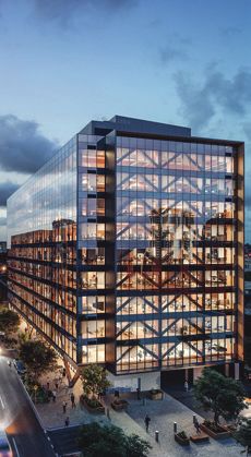
CONTENTS
       Page

        2         OVERVIEW
              Page                                                     Page
              5      Grid Spacing and Element Configuration            13     Post and Beam Construction Components
              8      Building Height

        21        CONSIDERATIONS FOR POST AND BEAM CONSTRUCTION
              21     Project Drivers                                   28     Design for Construction
              24     Performance Requirements

       32         STRUCTURAL DESIGN
              32     Design Steps                                      37     Beam Design
              33     Common Grade and Sizes of Glulam & LVL            40     Column Design
              34     Design Actions                                    43     Lateral Design
              35     Serviceability Design                             44     Connections

ners   53 BUILDING CASE STUDIES
                                                   Partners
  Part58
       nPearBIBLIOGRAPHY
            rstners

                                   Funding for the NZ Wood Design Guides is provided by our partners:

                                                         NZ Wood Design Guides | Post & Beam Timber Building Construction   1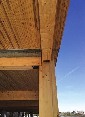
1 OVERVIEW
      Post and beam construction refers to a
      system where a buildings’ vertical support
      is built of beams and columns. Compared
      to conventional light timber framing, timber
      post and beam construction replaces the
      need for load bearing walls, allowing for
      large open spaces.

      Post and beam timber construction dates
      back well over a century in New Zealand
      and around the world. Auckland’s Kauri
      Timber Building Co built in the 1880s is
      a four-storey building with an internal
      post and beam gravity structure. The
      2018 restoration of this heritage building    Kauri Timber Building Co circa 1880s - Auckland.
      highlights the impressive use of Kauri and    New Zealand Historic Places Trust, Auckland.
      demonstrates a time-tested structural system.

      Timber buildings have many advantages beyond the inherent sustainable benefits of using a renewable material.
      Timber construction is light weight compared to other materials, making it easier to transport and crane into
      place, and in some situations requires lighter foundations. Timber can be erected efficiently due to the accuracy of
      prefabrication; this can minimise construction site time and result in a cleaner construction site with less dust, waste
      and noise. Exposed timber structures also provide the end user with a warm and inviting tactile space. Post and
      beam construction allows the creation of open, flexible spaces and creates opportunities for more building types to
      be constructed from timber.

     Ground floor of the restored heritage Kauri Timber Building Co (Photo :Patrick Reynolds).

2   NZ Wood Design Guides | Post & Beam Timber Building Construction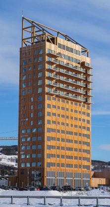
This guide focuses on multi-storey construction that utilises massive timber beam and column elements as the
primary gravity load carrying system. Common mass timber available in New Zealand includes Glue Laminated
Timber (Glulam), Laminated Veneer Lumber (LVL) and Cross Laminated Timber (CLT) panels.

This is an introductory design guide aimed at providing information and guidance on the planning and concept
design of timber post and beam buildings for developers, architects and engineers. References to more detailed
design guidance are provided in the relevant sections.

Around the world, the limits of mass timber are being pushed to create exceptional structures. Post and beam
buildings suit many applications including commercial, educational, residential, public or institutional. New Zealand
is already well on its way in paving the path for timber structures in high seismic zones. In depth case studies of some
New Zealand and international post and beam structures can be found in Section 4.0.

                                                                     Lightweight
                                                                       Frames

                                                                       Massive
                                        Frames                       Timber Post
                                                                       & Beam

                                                                        Post-
                                                                      Tensioned
                                                                       Frames

     Structural                                                         Frames
       Types                                                             Portal

                                      Solid Wood                    Massive Panel
                                       Systems                         Walls

                                                                    Massive Panel
                                                                       Floors

                                        Modular
                                        Systems

Summary of structural timber construction options. WoodSolutions Mid-rise Timber Building Structural Engineering.

                                                    NZ Wood Design Guides | Post & Beam Timber Building Construction       3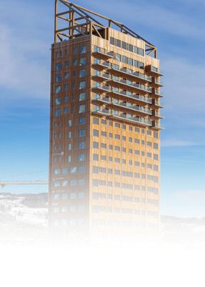
EDUCATION                                                     COMMERCIAL

     Beatrice Tinsley Building, Christchurch.                       Young Hunter House, Christchurch.
     Timber chosen to minimise weight of building, as existing      Timber chosen to minimise construction time and to facilitate a
     foundations were reused. Also chosen to showcase PRES-Lam      low damage design with high seismic performance.
     system pioneered at University of Canterbury.

                         RESIDENTIAL                                                        MEDICAL

     Carbon 12, Portland, US.                                       Hutt Valley Health Hub, Wellington.
     Timber was chosen in this 8-storey luxury apartment building   Timber chosen to facilitate a low damage design with high
     to create a sustainable design.                                seismic performance, and to make the space feel welcoming.

4   NZ Wood Design Guides | Post & Beam Timber Building Construction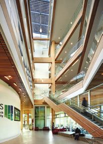
1.1 GRID SPACING AND ELEMENT CONFIGURATION
Determining the grid spacing is a critical design factor for mass timber buildings. There is no simple answer for the
‘best’ grid option as there are benefits and challenges to different layouts. Layouts and member configurations should
be determined with input from the whole design team early in the concept design phase. The overall floor depth is
dependent on the grid spacing and is often deeper for timber buildings than post and beam construction using other
materials.

A regular 5m x 5m or 5m x 6m grid spacing will produce an efficient timber post and beam system. It is recommended
that this close column spacing is considered first. As the beam spans increase, serviceability criteria (such as vibration)
start to govern the designs and the connections between members become more complex. Although possible, achieving
a 9m x 9m grid (as often desired for an office building) significantly increases cost and design complexity.

There are numerous configurations for the layout of post and beam structural elements. This section present some of
these for consideration, as well as providing examples of typical members sizes required for different grid arrangements.

1.1.1 One-way or Two-way Spanning Beams
Two common grid layout options are shown below. The first uses a one-way beam system, and the second a two-way
beam system.

One-way Beam System.

Two-way Beam System.

A one-way spanning beam system is materially efficient when the span of the floor system in one direction is
maximised. A one-way beam configuration also has advantages for the reticulation of services as they can run parallel
to the beam lines.

Two-way spanning beam systems are often chosen to provide fewer columns, especially if a mass timber CLT floor is
to be used.

A typical office mass timber CLT floor can span up to 6m while a cassette or composite floor can have greater spans
up to 10m but will result in a deeper floor build-up. Primary beams can be designed to span up to 9m with satisfactory
serviceability performance.

                                                 NZ Wood Design Guides | Post & Beam Timber Building Construction             5
1.1.2 Continuous Beams and Column
     The continuity of floors, beams, and columns should all be considered early in the concept design phase when
     determining the grid spacing. The logistics of transporting and lifting larger elements should form part of this process.

     Beams are often designed as simply supported members in post and beam structures; however, continuity over
     supports can reduce moments and control deflections. Continuity can be achieved with double beams running either
     side of single columns. Cantilevers in multi-span systems can also be used to reduce member sizes or optimise a single
     beam depth with uneven support spacing. Beam configurations must be considered in conjunction with columns as
     their interaction is key.

     Long continuous beam

     Cantilever beam system with larger beam at centre

     Cantilever beam system with smaller beam at centre

     Columns rearranged to suit single beam depth

     Beam Support Positions Utilising Cantilevers.

     Columns can be single storey, or continuous over 2 or more storeys. Continuous columns mean there are fewer
     elements to install, fewer column-column connections and less complex connection detailing at nodes. The length of
     columns from an erection standpoint must also be considered – a very long skinny element could have stability issues
     during construction.

     Detailing of the beam-column interface is important. Continuous beams will need to pass over the support. This can
     be achieved at the roof level, where the beam can span directly over the column: however, at intermediate levels the
     beams may need to be fixed to the side of the columns or the column area reduced by a notch. It is important that
     the connection detail avoids perpendicular to grain bearing on the beams (refer to Section 3.6 Column Design, for
     more information on perp to grain bearing). A double beam, one each side of the column could be used for continuity;
     however, fire considerations due to the extra surface area where charring can occur (refer to Section 2.2.3 Fire) could
     result in larger members.

     Similar to beams, floors can also be continuous over supports to help with the distribution of moments, deflection and
     can allow for a more efficient installation sequence (fewer elements to lift). The benefit of continuous flooring depends on
     the floor type and build-up requirements of the floor system.

     1.1.3 Examples of Post and Beam Element Sizes
     The following tables provide examples of element sizes for different grid spacing and element configurations. These are
     indicative only and should be used as such.

     Examples are provided for a CLT flooring on Glulam beams, and Cassette flooring supported by LVL beams; however,
     any combination of elements is possible: CLT flooring and LVL beams, Cassette flooring and Glulam beams, hybrid
     combinations, etc. Further possibilities for post and beam components are presented in Section 1.3.

6   NZ Wood Design Guides | Post & Beam Timber Building Construction
APPROXIMATE MEMBER SIZES – CLT FLOORING WITH GLULAM BEAMS

Layout (Grid)                   Secondary Beam        Primary Beam      CLT Panel Size
                                  (mm x mm)            (mm x mm)
5.0m panel x 5.0m beam                  -                180 x 585         5ply/225
5.0m panel x 6.0m beam                  -                180 x 675         5ply/225
5.0m panel x 7.0m beam                  -                230 x 720         5ply/225
6.0m x 6.0m                                                                                      Sec
                                    180 x 585            180 x 765          3ply/135                on
(secondary beams 3.0m crs)                                                                             da                              am
                                                                                                         ry                          Be
                                                                                                              Be               ary
7.0m x 7.0m                                                                                                     am         rim
                                    180 x 765           230 x 900          5ply/165                                       P
(secondary beams 3.5m crs)
8.0m x 8.0m
                                    180 x 855           230 x 1035         5ply/195
(secondary beams 4.0m crs)                                                                The figure shown is for a two-way beam system
                                                                                          where the floor spans between secondary beams.
                                                                                          Where there is no secondary beam, the floor spans
                                                                                          between primary beams.

NOTES:
- All member sizing must be confirmed for the conditions of your project.
- Design to NZS AS 1720.1 and AS/NZS 1170.
- Loading: SDL = 1.5kPa; Imposed, Q = 3kPa (imposed area reduction factor, ψa, included where applicable).
- Floor Panels assumed continuous over supports (1.25 load increase on internal beam).
- Beams assumed to be simply supported Glulam Grade 10 (GL10).
- Beam sizes are based on strength and vibration checks. The floor plate vibration is designed based on an assumed damping of 3% and a
  response factor of approx. 8 in line with guidance from SCI P354 (Smith, Hicks & Devine, 2009) and Concrete Centre CCIP-016 (Wilford & Young
  2006). See Serviceability Design Section for more information.
- Timber size from this table without additional fire protection achieve 30min fire rating which satisfies the usual sprinkler-protected office
  requirements.

APPROXIMATE MEMBER SIZES – CASSETTE FLOORING WITH LVL BEAMS

   Floor Span            Beam Span            Potius Box Beam            LVL Beam
                                            Cassette Depth (mm)         (mm x mm)
                            6.0m                                          178 x 550
      6.0m                                            350
                             7.0m                                         178 x 650
                            6.0m                                          178 x 600
       7.0m                                           450
                             7.0m                                         178 x 650
                             7.0m                                         178 x 700
      8.0m                                            520
                            8.0m                                          178 x 800

NOTES:
- All member sizing must be confirmed for the conditions of your project.
- Design to NZS AS 1720.1 and AS/NZS 1170.
- Loading: SDL = 1.5kPa; Imposed, Q = 3kPa (imposed area reduction factor, ψa, included where applicable). Panel self-weight = 0.4 - 0.6kPa.
- Floor Panels: simply supported based on Potius Box Beam cassette span tables for 30min FRR.
- Beams assumed to be simply supported of LVL13 grade material.
- Beam sizes are based on strength and vibration checks. The floor plate vibration is designed based on an assumed damping of 3% and a
  response factor of approximately 8 in line with guidance from SCI P354 (Smith, Hicks & Devine, 2009) and Concrete Centre CCIP-016 (Wilford &
  Young 2006). See Serviceability Design Section for more information.
- Beam depths have been optimised for strength and serviceability, consult with timber supplier on best beam depth to limit offcut wastage.
- Timber size from this table without additional fire protection achieve 30min fire rating which satisfies the usual sprinkler-protected office
  requirements.

                                                         NZ Wood Design Guides | Post & Beam Timber Building Construction                         7
APPROXIMATE MEMBER SIZES – COLUMNS BASED ON AXIAL LOAD
         Glulam GL10                            LVL13                    Factored Axial Load             Approximate Area Description
         (mm x mm)                            (mm x mm)                   1.2G+1.5ψaQ (kN)

            180x180                              178x180                           150                   4m x 5m x 1 storey = 20m2

            225x225                             222x200                            375                   5m x 6m x 2 storeys = 60m2

            270x270                             222x260                            720                   6m x 7m x 3 storeys = 126m2

            315x315                             267x270                           1145                   6m x 7m x 5 storeys = 210m2

            360x360                             300x300                           1600                   6m x 7m x 7 storeys = 294m2

      NOTES:
      - The above table is based on a column length of 3.3m (Lay=Lax = 3.3m), and the area examples are based on 2.0kPa permanent and 3kPa
        imposed load (office). The imposed action reduction factor, ψa, is included as appropriate. Floors are assumed to be simply supported.
      - Columns are checked for combined axial and bending with bending taken as the imposed load on one beam multiplied by half of the column
        depth.
      - Design to NZS AS 1720.1 and AS/NZS 1170.
      - The characteristic strengths are taken from manufacturer provided strengths (fc’=26MPa for GL10; fc’=38MPa for LVL13).
      - Timber sizes from this table without additional fire protection achieve 30min fire rating which satisfies the usual sprinkler-protected office
        requirements.

     1.1.4 Using every material for its strengths

     This guide focuses on timber post and beam components; however, these timber elements can be used in conjunction
     with other materials. Some examples of hybrid applications are:

        •     Steel or concrete beams incorporated in a timber post and beam structure for longer spans.

       •      Concrete or steel columns may be advantageous when used in combination with different lateral systems.
     		      (Wynn Williams House in Christchurch uses concrete columns with post-tensioned timber beams).

        •     To create open areas in a mass timber wall building (such as in the Otago Polytechnic Student Village).

       •     It is also common for a timber post and beam structure to be used to support a concrete floor (such as in Lucas
     		      House in Nelson and Kahukura CPIT in Christchurch that both use concrete prestressed rib and infill floors).

     1.2 BUILDING HEIGHT
     While New Zealand has no specific limit for the height and size of timber structures, compliance with the Building Code
     must be achieved. The maximum height of timber buildings is dependent on fire performance, as well as practical limits
     due to size of structural elements, cost, seismic performance and wind sensitivity. Exposed structural timber contributes
     to the fire load which is not normally accounted for in non-combustible structures and thus makes the fire design more
     complex. The main limiting factors are safe egress routes and fire fighter access. However, a 2018 case study (SFPE NZ,
     2018), demonstrated how a theoretical 30 storey timber apartment building in Auckland could achieve acceptable fire
     performance. A qualified Fire Engineer with timber building experience should be consulted on this topic.

     Around the globe, timber engineering is pushing new heights. There are many universal similarities; however, every
     country has different building regulations. Australia for instance changed their National Construction Code in 2016
     to allow timber buildings up to 25m high (8-9 storeys). The use of alternative solutions; however, led to the design
     and completion of 25 King Street in Brisbane, which is 10 storeys and 45m tall. Norway currently has the tallest full
     mass timber building in the world, Mjøstårnet, which is 18 storeys, with the top occupied level at 68m and much of the
     structural timber exposed. The Ho Ho Building in Vienna, Austria, is even taller at 24 storeys, 84m tall, and achieves this
     using concrete core shear walls for the lateral system. In the United States, there is a push for acceptance of taller wood
     buildings, and as such the 2021 International Building Code (IBC) includes provisions for up to 18 storeys for business and
     residential occupancies (Breneman, 2019).

8   NZ Wood Design Guides | Post & Beam Timber Building Construction
In New Zealand, seismic design can also be a limiting factor for the size of timber buildings. The building aspect
ratio, seismic loading and lateral load resisting system (LLRS) must be considered early in the concept design when
considering building height. Timber buildings above 4 storeys in New Zealand are likely to be viewed as an alternative
solution and peer review likely requested by Councils. Tall timber buildings are being designed in other seismic regions
of the world; examples include: Carbon 12, an 8 storey mass timber apartment building in Portland, Oregon and Brock
Commons, an 18 storey CLT panel – column point supported structure with concrete core shear walls in Vancouver,
BC. The 2150 Keith Drive project also in Vancouver is expected to be the tallest timber braced frame building in North
America at 10 storeys.
Mjøstårnet, Norway: 18 storey post and beam structure . 25 King Street, Brisbane: 10 storey post and beam structure.
NZ Wood Design Guides | Post & Beam Timber Building Construction 91.3 POST AND BEAM CONSTRUCTION COMPONENTS
During the concept design phase of a post and beam structure, the benefits of different types of floors, beams,
columns and lateral systems should be explored. The architect and structural engineer should collaborate with
other design professionals on the team as well as material suppliers to determine the most suitable options and
material availability for the project. Consideration of fire protection, façade and integration of services within the
structure is also critical at an early stage and can affect the component choice – refer to Section 2 for more on these
topics. An overview of several types of floors, beams and columns are detailed in this section, as well as lateral
systems which can be used with post and beam gravity systems. Foundations, podium levels, roof systems and
façades are also discussed.
1.3.1 Floors
The floor elements in any mass timber building can have a significant impact on the layout, aesthetic, cost and
performance of the structure. Timber floors generally fall into two categories, mass timber floors and timber framing
systems. Both types can be prefabricated off site. There are numerous considerations when deciding which type of
flooring system to use including:
• Span – vibration, strength, deflection.
• Floor depth – impact on floor to floor height, supported on beam or face fixed.
• Topping – carpet, timber flooring, acoustic mats, concrete screed. Consider construction, weight, acoustics,
durability, aesthetics (for example: concrete adds a wet trade and can drip / leach on to other exposed timber if
not protected properly).
• Services Integration – in floor topping or floating floor, within joist depth, below floor or integrated within
beams (see Section 2.2.4).
• Cost – unit cost, transportation, installation, finishing.
• Aesthetics – exposed, covered, coatings, timber visual grade.
• Acoustic performance – required rating, linings, fixings, topping.
• Tolerance – moisture effects, construction tolerance.
• Fire considerations – rating, spread of flame, linings, penetrations.
• Support connections – ease of install, continuous spans, simply supported, durability, fire performance.
• Diaphragm capability – connection between panel units, chords, collector connections, fastener edge
distances.
• Supply – availability, lead time, design advice.
• Prefabrication – built on or off site, controlled environment, transportation restrictions.
• Installation – temporary support, crane size and hook time, access, safety.
Many of the performance requirements listed above are further discussed in Section 2 of this guide. Non-timber
floor systems can also be used in timber post and beam construction. Examples include Ara Kahukura Building in
Christchurch which uses a precast concrete rib and infill system. Floor system suppliers often provide span tables
for their floor systems. Alternatively, the Wood Solutions Guide number 46 “Wood Construction Systems” provides
indicative spans for both floor joists systems and solid CLT floor panels.
Several common timber floor types are discussed in the following table.
10 NZ Wood Design Guides | Post & Beam Timber Building ConstructionFLOOR SYSTEM FEATURES EXAMPLES
✓ Potential for two-way spanning
system (typically spans up to 6m in
principle direction).
✓ Allows for thin floor thickness.
✓ Aesthetics (exposed timber).
✓ Fast installation.
✓ Penetrations for services are easier in
two-way system.
CROSS LAMINATED TIMBER (CLT) ✓ Supplier design advice available.
Engineered wood product made up of several layers ✓ Dimensionally stable compared to
of timber boards stacked at right angles and glued other mass timber panels.
together on their wide faces. CLT is generally made
up of an odd number of laminations from 3 to 7 ✗ Not structurally efficient in terms of
layers with the outer layers parallel to the major span wood fibre.
direction. Panels can be made up to 3.5mx15m but ✗ May need to conceal to meet spread
are typically fabricated up to 3.0m x 12.0m based on of flame requirements in residential
transportation limitations. Panel thicknesses vary and limit fuel for fire design.
from approx. 105mm to 225mm however can be made ✗ Limited supply options in NZ impacts
up to 315mm (XLam 2017). lead times and cost.
NZ manufacturers include:
Red Stag Timber is currently (2020) building a CLT
Plant in Rotorua. XLam (fabrication facilities in
Australia) supply CLT to NZ.
✓ Integration of services in cavities.
✓ Light weight and materially efficient.
✓ Longer span solutions possible.
(Typically spans 5-10m).
✓ Insulation & acoustic linings can be
included in prefabrication.
✓ Refer to NZ Wood Design Guide ‘Floor
and Roof Cassette Systems’ for more
information.
CASSETTES / BOX BEAMS
Prefabricated panels consisting of joists, or truss ✗ Fire protection often required.
beams, blocking and at least one layer of sheathing. ✗ Lifting can be an issue with thin
Cassettes come in several forms including box beam sheathing panels.
floor panels, I-beam or T-beam joists, and timber, steel
or hybrid truss beams.
NZ manufacturers include:
MiTek, Potius Building Systems, Pryda, Concision
Panelised Technology, CleverCore.
✓ One-way spanning system (Typically
spans up to 6m).
✓ Potentially lesser depth than CLT due
to single span direction.
✓ Many supply options in New Zealand.
✗ May require details to accommodate
transverse shrinkage.
GLUE LAMINATED TIMBER (GLULAM) ✗ Reinforcement for penetrations may
be required.
PANELS ✗ Limited width (typ. 900mm) increases
This engineered product is made up of timber boards number of lifts required unless off-site
laminated together on edge with all boards running splice is used.
parallel to the span direction. Typical panel depths ✗ Sheathing or reinforced concrete
90mm to 140mm. topping may be required for
NZ manufacturers include: diaphragm action.
Prolam, Techlam, Timberlab, Woodspan PLT, HTL Group.
Continued next page...
NZ Wood Design Guides | Post & Beam Timber Building Construction 11FLOOR SYSTEM FEATURES EXAMPLES
✓ Longer spanning capacity than
normal mass timber panels.
✓ Stiffer design with higher mass
leading to better vibration and
acoustic performance.
✓ Good diaphragm performance and
easy to connect into a concrete lateral
system.
✓ Increase fire performance with careful
TIMBER CONCRETE COMPOSITE (TCC) design.
TCC utilizes the combined strength of timber floor
panels (or beams) with the added strength of the ✗ Requires additional trade / more
concrete topping for the compression flange. Spans coordination.
up to 12m are possible. ✗ Preparation for topping pour can be
time intensive.
✗ Concrete slurry can leak creating
issues with exposed timber.
✗ Adds weight and seismic mass.
✓ Flexibility in construction.
✓ Transportation of smaller elements
can be easier.
✓ Can be used as “infill” between other
floor systems.
✓ May not require craning.
✗ Does not provide working platform
during construction.
TIMBER FRAMING ✗ Will probably require fire protection.
Traditional timber framing can be used with post and ✗ Additional requirements for acoustic
beam structures. Sawn timber or engineered joists performance.
can bear on the top of beams or be supported with ✗ Limitations on size and capacity for
proprietary brackets similar to light timber frame long spans.
construction.
✓ Easy to fabricate offsite or in place.
✓ One way spanning system (Typically
spans up to 6m).
✗ Moisture expansion must be
considered in design and detailing.
✗ Reinforcement for penetrations may
be required.
✗ Sheathing may be required for
NAIL LAMINATED TIMBER (NLT) diaphragm action.
NLT is similar to GLT however the laminations are
either nailed or screwed instead of glued together.
This economical type of mass timber panel along with
DLT (dowel laminated timber) are common types of
mass timber panels in North America and Europe,
however, are not as common in New Zealand.
✓ Long span solution.
✓ Good diaphragm performance and
easy to connect into a concrete lateral
system.
✓ Low overall floor depth.
✗ Requires additional trade / more
coordination.
✗ Timber is not the primary flooring
HYBRID SOLUTIONS material.
Hybrid floor solutions also work with timber post ✗ Concrete slurry can leak creating
and beam structures. Concrete rib & infill panels, issues with exposed timber.
prestressed concrete panels, or corrugated composite ✗ Adds weight and seismic mass.
steel and concrete flooring are also options.
NZ manufacturers include:
Stalhton, Preco, Stresscrete, Comflor, Tray-dec.
12 NZ Wood Design Guides | Post & Beam Timber Building Construction1.3.2 Beams
Beams support the floor elements and transfer load to the columns. Sometimes larger “primary beams” support
secondary beams in order to reduce the floor span while maintaining a larger column grid. Some considerations when
determining the type of beam element to use include:
• Span – vibration, strength, deflection, single or continuous spans to control deflection, camber.
• Torsion – eccentric loading.
• Beam geometry – lateral buckling, material efficiency, impact on floor to floor height, manufacturer sizing.
• Integration of services – within floor, beam penetrations and reinforcement.
• Cost – unit cost, transportation, installation, finishing.
• Aesthetics – exposed, covered, coatings, timber visual grade.
• Tolerance – moisture effects, construction tolerance.
• Fire considerations – rating, linings, penetrations.
• Support connections – continuous, simply supported, complexity, ease of install, durability, fire, displacement
compatibility.
• Lateral system – collector beams, diaphragm chords.
• Supply – availability, lead time, manufacturer preferred size and grade (refer to Section 3.1 for LVL and Glulam).
• Prefabrication – controlled environment, machining, penetrations for services, transportation restrictions.
• Installation – temporary support, crane size and hook time, access, safety, buildability.
The most common type of beams used in timber post and beam construction are solid engineered timber beams (LVL or
Glulam). The features of these, along with several other beam options are discussed in the following table.
More detail on beam design and an example gravity calculation is presented in Section 3.4. The Wood Solutions Guide
number 46 “Wood Construction Systems” provides indicative spans for LVL and Glulam beams less than 500 mm deep.
BEAM TYPE FEATURES EXAMPLES
LAMINATED VENEER LUMBER (LVL) ✓ High strength and stiffness compared
Engineered wood product to Glulam.
manufactured from thin ✓ Cross banded layers to resist splitting
wood veneer elements are possible but more expensive.
which are glued together ✓ Readily available in NZ.
with a durable adhesive ✗ Curve and camber achieved by
primarily with its grain cutting.
direction parallel to the ✗ Potentially not as aesthetically
main axis of the member. pleasing as glulam with visible glue
LVL is manufactured in lines and potential checking over time.
large panels up to 1.2m
wide by 18m long and then
cut to size. It can be used for beams, columns, floor
panels and walls. See Section 3.2 for common grades
and sizes.
NZ manufacturers include:
CHH Futurebuild, Nelson Pine, Juken NZ.
GLUE LAMINATED TIMBER (GLULAM) ✓ Can be manufactured in almost any
size and shape.
Similar to CLT, glulam
✓ Numerous strength grades.
consists of laminated
✓ Aesthetics – visually appealing.
elements bonded
✓ Can be precambered or curved in
together with durable,
production.
water-resistant adhesives
on its flat face. All the ✗ Less strength than equivalent size LVL.
laminations run parallel ✗ Potential cost premium compared
to the length of the with LVL.
member creating a one-
way spanning element.
Glulam can be made
into many sizes and lengths are generally limited by
transportation. See Section 3.2 for common grades
and sizes.
NZ manufacturers include:
Prolam, Techlam, Timberlab, HTL Group.
Continued next page...
NZ Wood Design Guides | Post & Beam Timber Building Construction 13BEAM TYPE FEATURES EXAMPLES
BOX OR I-BEAMS ✓ Lightweight.
✓ Structurally efficient.
These beams are generally
✓ Simple to construct.
made from sawn timber
✓ Services integration.
or LVL flanges, glued or
✓ Prefabricated or site assembled.
nailed to webs made of
plywood, crossbanded LVL ✗ May require fire resistant linings.
or oriented strand board ✗ I-beams are generally covered (not
(OSB). Specific design visible).
typically required for larger beams. ✗ More complex to design if not using
NZ manufacturers include: proprietary product.
Commercial: Timberlab, Potius Building Systems,
Techlam.
Residential: Lumberworx, CHH Futurebuild.
POST-TENSIONED BEAMS ✓ High strength.
✓ Low deflection.
Post-tensioned timber beams use a similar technology
✓ Fewer internal columns or walls.
to prestressed concrete.
✓ Incorporation with Pres-Lam lateral
The beams are generally
technology.
made of glulam or LVL
‘box’ elements with high ✗ Complex to design.
strength steel bars or ✗ Consideration of fire required for
tendons running through tendons although often not governing.
the cavity and anchored at ✗ Requires good understanding of
the ends. timber creep and shrinkage.
✗ Timber elements are more likely to be
shear governed.
✗ Use of post tensioning does not alter
member stiffness or improve vibration
performance.
FLITCH BEAMS ✓ Stiff beam due to the composite
action of the steel plate in its strong
A flitch beam is a composite beam formed with a steel
direction.
plate sandwiched between
✓ Lesser depth for same span.
two timber elements. The
✓ Typically used for large residential
timber elements restrain
lintels or where beams are covered.
the thin steel plate from
buckling while bending in ✗ On site modifications are difficult.
its strong axis. ✗ Bolt requirements can be difficult to
NZ manufacturers properly calculate.
include: ✗ Fire protection likely required.
Residential: MiTek, Pryda. ✗ LVL beam is often a more cost-
effective solution.
HYBRID SOLUTIONS ✓ May be appropriate for long span
solutions.
Timber is a great material in many applications,
✓ Could be the right solution where
however, in general
shallow depth required.
timber should be used to
✓ High strength connections can be
its strengths. There are
welded.
instances where the use of
✓ Can be designed as a ductile link
steel beams for instance
when required.
could be a more practical
solution within a timber ✗ Fire protection likely required.
post and beam structure.
14 NZ Wood Design Guides | Post & Beam Timber Building Construction1.3.3 Columns
Column elements are the final step in the gravity load path of the superstructure. They transfer the load from the beams
to the foundation. When selecting the column type, many of the same considerations as for beams apply.
• Strength – effective length, eccentric loading, deflection, stability of gravity columns under lateral movement.
• Geometry – buckling, single or multiple storeys, square, rectangular or box, material efficiency, space
constraints.
• Cost – unit cost, transportation, installation, finishing.
• Aesthetics – exposed, covered, coatings, timber visual grade.
• Tolerance – moisture effects, construction tolerance.
• Fire considerations – rating, linings.
• Connections – complexity, ease of install, durability, fire, displacement compatibility, minimum demands.
• Lateral system – Integration with LLRS.
• Supply – availability, lead time, manufacturer preferred size and grade (refer to Section 3.2 for LVL and Glulam).
• Prefabrication – machining, transportation restrictions.
• Installation – temporary support, crane size and hook time, access, safety.
• Moisture Effects – temporary and long-term building shrinkage/shortening (refer to Serviceability Design),
foundation connection and mitigating construction moisture.
More detail on specific column design and an example gravity calculation is presented in Section 3.6. The most common
type of columns used in timber post and beam construction are solid engineered timber (LVL or Glulam). The features of
these, along with several other column options are discussed in the following table.
NZ Wood Design Guides | Post & Beam Timber Building Construction 15COLUMN TYPE FEATURES EXAMPLES
LAMINATED VENEER LUMBER (LVL) ✓ High strength and stiffness compared
to Glulam.
Engineered wood product manufactured from thin
✓ Cost effective option.
wood veneer elements which are
glued together with a durable ✗ Potentially not as aesthetically
adhesive primarily with its pleasing as glulam with visible glue
grain direction parallel to the lines and potential checking over time.
main axis of the member. LVL is ✗ Can be more diffcult to install
manufactured in large panels fasteners due to higher density,
up to 1.2m wide by 18m long and however, can result in higher fastener
then cut to size. It can be used for capacity.
beams, columns, floor panels and
walls. See Section 3.2 for common
grades and sizes.
NZ manufacturers include:
CHH Futurebuild, Nelson Pine,
Juken NZ, HTL Group.
GLUE LAMINATED TIMBER (GLULAM) ✓ Aesthetics – visually appealing.
✓ Easy to work with.
See beams description. Also
✓ Large section sizes available.
note, where members wider
than 230mm are required, block ✗ Potential cost premium compared to
glulam can be used. This comes LVL.
at a cost premium as edge gluing
of smaller boards is required (see
Section 3.2 for more info).
NZ manufacturers include:
Prolam, Techlam, Timberlab.
BOX OR I SECTION COLUMNS ✓ Efficient design.
✓ Simple to construct.
Box columns are composite
✓ Services integration.
sections generally made of sawn
or engineered timber nailed ✗ More complex to design.
or glued together. This type of ✗ May be labour intensive.
composite column is efficient ✗ May require fire resistant linings.
and light weight.
HYBRID SOLUTIONS ✓ Use for high demand situations.
✓ Incorporation with lateral system.
Columns can be made of
alternative materials and ✗ Consideration of fire for steel columns.
incorporated with timber beams ✗ Need to consider differential creep
and floors. Wynn Williams House movement if used in parallel with
is an example in Christchurch that timber elements.
uses concrete columns with ✗ Intergration of materials requires
post-tensioned LVL beams. compatibility of tolerances, structural
properties, durability, etc.
16 NZ Wood Design Guides | Post & Beam Timber Building Construction1.3.4 Lateral Load Resisting Systems (LLRS)
Timber post and beam systems are often designed as gravity systems with other lateral load resisting systems. The LLRS
transfers horizontal earthquake and wind loads through the structure to the foundation. Considerations for the lateral
load design of post and beam structures are discussed in more detail in Section 3.7. Detailed guidance on timber lateral
systems can be found in the NZ Wood Guide “Seismic Design”.
The LLRS options for post and beam construction predominantly include timber shear walls (CLT or plywood), concrete
shear walls, diagonal bracing systems (steel or timber) and moment frames. A high-level overview of these systems is
provided in the table below.
ELEMENT FEATURES EXAMPLES
LIGHT TIMBER FRAME SHEAR WALLS ✓ Economical, common material.
✓ Fast to construct.
Light timber frame (LTF) shear walls are typically used
in residential applications or areas of buildings with ✗ Flexible (less stiff than solid timber wall
many walls. A sheathing material such as plywood or systems).
OSB is fixed to timber framing and used for the shear ✗ Many walls required.
resistance. This type of LLRS is not common for the ✗ Not common for taller post and beam
larger post and beam construction due to the number buildings in seismic regions.
of walls required. ✗ Fire proofing required.
CLT OR LVL SHEAR WALLS ✓ Can be prefabricated off site and
installed quickly.
Mass timber shear walls are more common in larger
✓ Can be incorporated into seismic
timber buildings than LTF shear walls. In post and
resilient systems.
beam construction mass timber shear walls can be
✓ Walls can be concealed in the core of
contained in the core of the building or distributed
the building.
throughout. Ductility can be provided in the
connections (panel joints and hold-downs). ✗ May have a cost premium compared
to a bracing system.
✗ Fire proofing may be required.
CONCRETE SHEAR WALLS ✓ Stiff system – less drift.
✓ Often fewer shear walls required.
Concrete shear walls are often used as cores
✓ Can incorporate pathways for
centralised within the timber post and beam gravity
services, stairs and elevators.
system.
✓ Non-combustible material - can be left
exposed/ used as fire wall.
✗ Cost - more expensive than a timber
solution.
✗ Slower site construction time.
✗ Introduces new trade to job site.
✗ Differential vertical movement.
✗ Transferring lateral force through the
timber diaphragm into the concrete
wall can be challenging.
Continued next page...
NZ Wood Design Guides | Post & Beam Timber Building Construction 17ELEMENT FEATURES EXAMPLES
TIMBER MOMENT FRAMES ✓ Can be realised through Pres-Lam
seismic resistant system or other
Moment frames have been used in timber construction
forms of beam-column moment
for a long time. They are often known as portal frames
connections.
which are covered in further detail in NZ Wood design
✓ Safety in design – preassembly at
guide “Portal Knee Connections”.
ground level.
Multi-story moment frames are less common,
however, have been used in timber structures ✗ Larger crane required if pre-
including the Beatrice Tinsley building at the University assembled in large sections.
of Canterbury. ✗ Limited height due to frame flexibility.
TIMBER AND STEEL DIAGONAL ✓ Fast to install – concurrent install with
posts and beams.
BRACING ✓ Frames can be preassembled on the
Timber and steel diagonal bracing systems are being ground.
used more often in timber post and beam structures. ✓ Damping devices can be included to
They can provide an elegant lateral solution which can increase resilience.
be tied into the building’s aesthetics.
✗ Timber braces can become relatively
large with higher forces introduced.
✗ Particular attention required for
detailing connections.
DIAGRID FRAMES ✓ Structurally efficient.
✓ Removes need for vertical columns.
Diagrid frames are an efficient structural system
✓ Stiff lateral capacity.
that combine gravity and lateral resisting elements.
✓ Aesthetically pleasing.
Diagrids remove the need for vertical columns as the
diagonals resist both gravity and lateral forces. This ✗ Design can be complex.
technology has been used in some of the world’s most ✗ Potential cost premiums.
impressive timber structures.
All of the LLRS described above can be designed to include new technology and devices to enhance seismic performance
by adding damping and/or recentering to the structural system. Examples of such systems include:
• Tectonus – NZ designed friction-based damping device with a special configuration that can produce damping
and recentering. This proprietary product is being used in post and beam buildings including the Hutt Valley
Health Hub (Lower Hutt, NZ) and the Fast + Epp Head Office (Vancouver, Canada). Designers should contact
Tectonus for more information and design guidance.
• Pres-Lam – NZ designed post-tensioned timber building system. Post-tensioning is used in conjunction with
dissipation devices to add damping and recentering to the structure. Pres-Lam technology is patented in
New Zealand and Australia by PTL Structural Consultants who should be contacted for use. Post and beam
buildings that use the Pre-Lam technology include the Massey University CoCA building (Wellington, NZ), the
Trimble building (Christchurch, NZ), NMIT Arts and Media Building (Nelson, NZ).
• Buckling Restrained Braces (BRB) – BRB’s are an effective structural solution for seismic resilient structures and
have been used in steel construction for many years. Research is underway at the University of Auckland and
University of Christchurch on the performance of BRB’s in timber buildings, and it is likely that this technology
will be incorporated more regularly with timber post and beam structures. The Catalyst Building in Spokane,
Washington is the first building to utilize CLT shear walls with buckling-restrained braces as ductile hold-down
elements.
• Friction Springs – friction springs can be used to absorb energy in an LLRS. Friction springs can be tuned to
achieve the desired damping for a specific project. Ringfeder friction springs have been used in New Zealand
buildings including in the steel K-braces of the Tait Communications Headquarters in Christchurch.
18 NZ Wood Design Guides | Post & Beam Timber Building Construction1.3.5 Foundations and Podium Levels
The foundation design for timber post and beam construction is like that of other building types. The type of foundation
required will depend on the size of the building and local ground conditions. Concrete foundations are the most common,
but timber piles may also be an option for some buildings.
Timber structures are significantly lighter than the equivalent size concrete structure; therefore, the foundations can often
be lighter also. The benefits of less demand on a building’s foundations are considerable. Often a shallow, rather than a
piled foundation system can be used, resulting in less excavation and less foundation material being required. All of this
can lead to faster construction and cost savings.
Timber Superstructure
Podium
Subterranean Level
Podium Construction
Timber post and beam construction lends itself to
structures with a regular grid layout. However, often in
mixed use developments, there is a desire for a change
in layout at the ground floor or basement. To achieve
such transitions, it is common for timber post and
beam structures to be built on top of a concrete or steel
podium. The use of one or two podium levels are well
suited for ground floor carpark, retail and restaurant use,
and provide fire separation from the other commercial
or residential use in the timber stories above. Podiums
must be carefully designed to transfer any offset vertical
or horizontal design actions. The seismic design of such
a system is also important if transferring from the timber
LLRS to a concrete or steel LLRS.
T3 Atlanta - 6 storey post and beam, over one story podium
Prefabricated timber elements are fabricated with a (StructureCraft Builders).
high level of accuracy, it is therefore important that
the receiving structure also be constructed to a high level of accuracy. Timber connections will provide some tolerance,
however, the set out of the receiving structure, particularly if it involves cast in place elements must be carefully managed.
1.3.6 Roof Systems
The roof system of a post and beam building can be supported by beams and columns similar to the floor levels below.
The beams can be angled to suit the roof pitch and designed for the appropriate roof loading. However, efficient
long span roof assemblies can also be designed to allow some columns to be removed at the top level. Trusses, tied
frames, arches and portal frames can allow for additional flexibility in roof structures. Columns can also be designed as
cantilevers to support the roof level eliminating the need for bracing.
NZ Wood Design Guides | Post & Beam Timber Building Construction 19Green Roof. Photo: Martin Tessler.
Arched Glulam Lecture Hall. Photo: Martin Tessler. Post and Beam Atrium.
The Centre for Interactive Research on Sustainability (CIRS) at the University of British Columbia in Vancouver,
Canada incorporates timber post and beam and long-span glulam arched beams which supports a living roof.
1.3.7 Façade
The façade system of a timber post and beam building requires consideration in the concept design phase – many of the
considerations are common to steel or concrete structures. Some considerations include:
• Serviceability Requirements – deflection requirements for the system, short and long-term considerations.
• Perimeter Beam – is a perimeter beam required to support the façade?
• Slab offset –floor slab extension past column/beam (cantilever), this may be more of an issue for one way
spanning floor systems.
• Durability – envelope, weather proofing, maintenance program, condensation on supporting timber elements.
• Lateral System – Integration with lateral system along the perimeter of the building.
• Fire performance – combustible materials must be designed to reduce the risk of spread of fire over multiple
storeys.
• Constructability – tolerance for construction, prefabrication or preassembly offsite (LCT One Building).
Life Cycle Tower One is an eight-storey office building in Dornbirn, Austria. The façade panels incorporated pre-fixed columns to
improve installation time by reducing the number of lifts required.
20 NZ Wood Design Guides | Post & Beam Timber Building Construction2 CONSIDERATIONS FOR POST AND BEAM
CONSTRUCTION
This section provides an overview of things that should be considered when designing with timber post and
beam construction. The topics are divided into three sections; Project Drivers, Performance Requirements and
Constructability.
2.1 PROJECT DRIVERS
2.1.1 Cost
The cost of timber post and beam construction depends on numerous factors and are in many situations comparable
to the equivalent steel or concrete construction. A key to achieving a cost-effective timber building is designing to
maximise the benefits of timber from the concept stage. The cost of this construction type has value not only in the
short-term capital cost, but also in other non-direct ways. A study commissioned by Naylor Love compared the carbon
emissions and costs of a timber versus steel and concrete commercial building. They found that you can currently
achieve about 90 percent reduction in carbon emissions for as low as 3-4% cost premium (Steeman, 2019). A few
driving factors which impact cost for building with timber include:
• Foundation Costs – due to the reduced weight of the structure, potential savings in foundations.
• Speed of Construction – prefabrication allows for quick installation and programme efficiency.
• Reduced size of plant on site – smaller cranes and other plant can typically be used.
• Reduced team on site – fewer people are typically required to assemble timber post and beam structures.
• Return on Investment – Green Star-certified buildings have higher return on investment than counterparts
(NZGBC 2018).
• Indirect costs – quiet and clean construction site, environmental and social benefits.
This not an exhaustive list as there are many more considerations for the cost of timber post and beam buildings.
The NZ Wood Design Guide ‘Costing Timber Buildings’ provides more detailed information on this topic.
2.1.2 Environmental Sustainability
It is well known that timber has environmental benefits over other mainstream construction materials. It is the only
structural material that can be grown with sun and water! The NZ Wood Design Guide ‘Timber Carbon and the
Environment’ provides background and context on the Carbon
footprints of buildings made from wood.
Additional benefits of timber post and beam construction are the future
flexibility of space use that is provided due to the open plan structure
compared to light timber frame structures where walls can limit the
use of spaces. Post and beam structures are a structurally efficient use
of timber and can be designed for deconstruction. The Circl pavilion in
Amsterdam, is a timber post and beam building designed using long,
unnotched members that are fully demountable. This will make them
easier to re-use at the end of its useful life and contribute to a circular
economy.
CIRCL Pavilion, Amsterdam.
NZ Wood Design Guides | Post & Beam Timber Building Construction 21Devonport Library, Athfield Architects. Nelson Airport, Studio Pacific Architecture.
2.1.3 Aesthetics and Well-being
Timber naturally provides a beautiful aesthetic. The many variations of species and intricacies of wood align with
human senses. Exposed timber is warm, rich and creates an environment conducive to human wellbeing and can
lead to stress reduction (Fell, 2010). Biophilic design is the connection of occupants of indoor spaces to the natural
environment through use of sunlight, plants and natural materials including wood. The 2015 report, Wood as a
Restorative Material in Healthcare Environments by FPInnovations shows that the use of wood and other natural
materials has positive health benefits for humans in the built environment. In the commercial realm wood can also be
attributed to increased productivity. The Pollinate 2018 report claims that office productivity can be increase by 8% and
well-being increased by 13%. There are many more studies in this area that show a trend of the positives of wood in built
environments. Often the best way to achieve these benefits are through the exposure of structural timber.
Refer to NZ Wood Design Guide ‘Social and Health Benefits of Timber Construction’ for more information.
2.1.4 Maintenance and Durability
Dry timber is a durable material which can last for centuries. Nonetheless care must be taken with timber structures to
ensure their longevity. The timber in post and beam buildings is generally enclosed inside the building envelope and
requires minimal maintenance. Interior timbers not exposed to moisture should be inspected periodically to ensure
the quality and performance of the elements have not degraded. Exterior timbers exposed to weather will require
more regular maintenance to ensure that strength and aesthetics are maintained (periodic sanding, coating, etc.).
Product manufacturers often provide specific warranties and maintenance criteria for their products which can be
found in their technical resources.
All structural timber which cannot be kept dry must be chemically treated or
be shown to have adequate durability (i.e. be a naturally durable species).
Interior timber will generally require little or no treatment as it falls in
the Hazard Class H1.1 or H1.2. Coatings supplied by the manufacturer
to protect against moisture and UV during construction are often
specified and should be discussed with manufacturers during the
design phase.
If non-durable timber is exposed to the elements it can be made more
durable through higher levels of treatment to prevent deterioration. The
durability of timber through treatment is classified into 6 Hazard Classes,
H1 to H6, as referenced above. The NZ Wood Design Guide “Trees, Timber,
Species & Properties” outlines these Hazard Classes and typical uses.
22 NZ Wood Design Guides | Post & Beam Timber Building Construction2.1.5 Moisture Effects
Moisture effects are the changes in timber properties and dimensions with changes in humidity and temperature.
Generally, timber tends to shrink and swell perpendicular to the grain and moisture ingress is greater at the end grain.
Moisture effects must be taken into consideration in the design and detailing of timber projects. Effective ways to
protect timber structures from moisture include detailing to allow for shrinkage, protecting wood from direct moisture
contact, and allowing wood to breathe once in place to release moisture. Refer to Section 2.3 Design for Construction
for further information on moisture effects during construction.
More information on the mechanism of moisture change and effect on wood can be found in the NZ Wood Design
Guides “Trees, Timber, Species & Properties” and “Construction Guidance”.
2.1.6 Safety in Design
Safety in design (SiD) is a great opportunity to contribute to the short, medium and long-term safety of structures.
Intelligent designs aim to anticipate and eliminate potential risks. SiD should be applied in the planning and design
stage to be effective throughout construction, modification and demolition of the structure. Post and beam structures
have ample opportunities for SiD, some items to consider include:
• Safe Construction Methods – design to eliminate higher risk construction tasks such as work at heights.
Prefabrication inherently includes this as tasks are done in a controlled environment. Determine further
opportunities for assembly of elements at ground level, such as braced frames, roof elements, etc. Timber
components can often be constructed with temporary safety barriers attached before being lifted into place.
The lightweight nature of timber can also reduce the number of truck and crane movements required.
• Future Adaptability – minimise construction difficulty if the structures are updated or altered.
• Maintenance – working with the design team and other stakeholders to identify the best and safest ways to
maintain the structure.
• Low Damage Design – design the structure for low damage in the event of earthquake or other events. If the
structure includes fuses, ensure they easily accessible for replacement after a design level event.
• Building End of Life – Design for ease of demolition for the end of the structure’s life. Post and beam buildings
often inherently include ease of dismantling due to how prefabricated elements are assembled on site.
2.1.7 Consenting
The consenting process is covered in detail in the NZ Wood Design Building Act
Guide “Consenting Timber Buildings”. Further information on
compliance, specifically regarding prefabrication and the
Building Code
benefit of robust quality assurance systems can be found in
Legislation
the NZ Wood Design Guide “Designing for Prefabrication”.
Alternative Solutions Verification Acceptable
Methods Solutions
2.1.8 Procurement
Standards Cited Standards
The local supply of timber products can be
Alternative Solution Route Deemed-to-Comply Route
a defining factor on projects. There are
numerous timber product options for post Building Regulatory Framework.
and beam structures, nonetheless early supplier
engagement is key for the success of timber projects.
Section 5 of the NZ Wood Design Guide “Designing for Prefabrication” discusses the process of procurement in more detail.
NZ Wood Design Guides | Post & Beam Timber Building Construction 23You can also read