Laser produced electromagnetic pulses: generation, detection and mitigation - Cambridge ...
←
→
Page content transcription
If your browser does not render page correctly, please read the page content below
High Power Laser Science and Engineering, (2020), Vol. 8, e22, 59 pages.
             doi:10.1017/hpl.2020.13

             REVIEW

             Laser produced electromagnetic pulses: generation,
             detection and mitigation

             Fabrizio Consoli 1 , Vladimir T. Tikhonchuk 2,3 , Matthieu Bardon4 , Philip Bradford 5 ,
             David C. Carroll 6 , Jakub Cikhardt 7,8 , Mattia Cipriani 1 , Robert J. Clarke 6 , Thomas E. Cowan 9 ,
             Colin N. Danson 10,11,12 , Riccardo De Angelis 1 , Massimo De Marco13 , Jean-Luc Dubois 2 ,
             Bertrand Etchessahar4 , Alejandro Laso Garcia 9 , David I. Hillier10,12 , Ales Honsa 3 , Weiman Jiang14 ,
             Viliam Kmetik3 , Josef Krása 15 , Yutong Li 14,16 , Frédéric Lubrano4 , Paul McKenna 17 ,
             Josefine Metzkes-Ng 9 , Alexandre Poyé 18 , Irene Prencipe9 , Piotr Ra̧czka 19 , Roland A. Smith 20 ,
             Roman Vrana3 , Nigel C. Woolsey 5 , Egle Zemaityte17 , Yihang Zhang14,16 , Zhe Zhang 14 ,
             Bernhard Zielbauer21 , and David Neely 6,10,17
             1 ENEA, Fusion and Technologies for Nuclear Safety Department, C.R. Frascati, 00044 Frascati, Italy
             2 CELIA, University of Bordeaux, CNRS, CEA, 33405 Talence, France
             3 ELI Beamlines, Institute of Physics, Czech Academy of Sciences, 25241 Dolnı́ Břežany, Czech Republic
             4 CEA, DAM, CESTA, 33116 Le Barp, France
             5 Department of Physics, York Plasma Institute, University of York, Heslington, York YO10 5DD, UK
             6 Central Laser Facility, Rutherford Appleton Laboratory, STFC, UKRI, Chilton, Didcot, Oxfordshire OX11 0QX, UK
             7 Czech Technical University in Prague, Faculty of Electrical Engineering, 166 27 Prague 6, Czech Republic
             8 Institute of Plasma Physics of the Czech Academy of Sciences, Za Slovankou 3, 182 00 Prague, Czech Republic
             9 Helmholtz-Zentrum Dresden-Rossendorf, Institut für Strahlenphysik, 01328 Dresden, Germany
             10 AWE plc, Aldermaston, Reading, Berkshire RG7 4PR, UK
             11 OxCHEDS, Clarendon Laboratory, Department of Physics, University of Oxford, Oxford OX1 3PU, UK
             12 CIFS, The Blackett Laboratory, Imperial College London, London SW7 2AZ, UK
             13 Centro de Laseres Pulsados (CLPU), 37185 Villamayor, Salamanca, Spain
             14 Beijing National Laboratory for Condensed Matter Physics, Institute of Physics, Chinese Academy of Sciences, Beijing 100190,
             China
             15 Institute of Physics of the Czech Academy of Sciences, Na Slovance 2, 182 21 Prague, Czech Republic
             16 School of Physical Sciences, University of Chinese Academy of Sciences, Beijing 100049, China
             17 Department of Physics, Scottish Universities Physics Alliance (SUPA), University of Strathclyde, Glasgow G4 0NG, UK
             18 Laboratory PIIM, University Aix-Marseille-CNRS, 13397 Marseille, France
             19 Institute of Plasma Physics and Laser Microfusion, 01-497 Warsaw, Poland
             20 The Blackett Laboratory, Imperial College London, London SW7 2AZ, UK
             21 PHELIX Group, GSI Helmholtzzentrum für Schwerionenforschung, D-64291 Darmstadt, Germany

             (Received 7 December 2019; revised 26 February 2020; accepted 10 March 2020)

                  Correspondence to: F. Consoli, ENEA, Fusion and Technologies for Nuclear Safety Department, C.R. Frascati, 00044 Frascati,
             Italy. Email: fabrizio.consoli@enea.it

             © The Author(s) 2020. This is an Open Access article, distributed under the terms of the Creative Commons Attribution licence (http://creativecommons.org/
             licenses/by/4.0/), which permits unrestricted re-use, distribution, and reproduction in any medium, provided the original work is properly cited.
                                                                                                1
Downloaded from https://www.cambridge.org/core. 30 Sep 2020 at 16:02:23, subject to the Cambridge Core terms of use.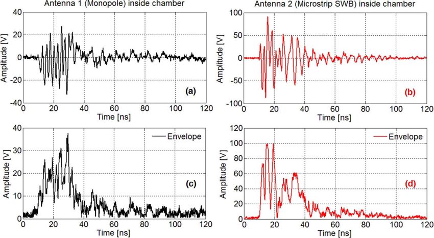
2                                                                                                                                   F. Consoli et al.

       Abstract
       This paper provides an up-to-date review of the problems related to the generation, detection and mitigation of strong
       electromagnetic pulses created in the interaction of high-power, high-energy laser pulses with different types of solid
       targets. It includes new experimental data obtained independently at several international laboratories. The mechanisms
       of electromagnetic field generation are analyzed and considered as a function of the intensity and the spectral range of
       emissions they produce. The major emphasis is put on the GHz frequency domain, which is the most damaging for
       electronics and may have important applications. The physics of electromagnetic emissions in other spectral domains,
       in particular THz and MHz, is also discussed. The theoretical models and numerical simulations are compared with the
       results of experimental measurements, with special attention to the methodology of measurements and complementary
       diagnostics. Understanding the underlying physical processes is the basis for developing techniques to mitigate the
       electromagnetic threat and to harness electromagnetic emissions, which may have promising applications.
       Keywords: electromagnetic pulses; high-power lasers; diagnostics; mitigation techniques

       1. Introduction: why the electromagnetic pulses are so                                  major EMP mitigation approach. The understanding of the
       important                                                                               physics of EMP generation has substantially advanced very
                                                                                               recently, and other mechanisms of EMP generation have
       Generation of electromagnetic waves was first demonstrated                              been identified. Among the related main research topics,
       by Heinrich Hertz in 1887 and since then has become                                     we mention: the excitation of chamber resonant modes; the
       a leading subject of research, with an enormous range                                   characterization of secondary EMP sources; the scattered
       of applications covering radio communications, electronics,                             radiation. These processes are discussed in Sections 2.5
       computing, radar technology and multi-wavelength astron-                                and 2.6 of this review. More accurate and efficient detection
       omy. The accessible spectrum of electromagnetic emissions                               methods have been developed and used to deliver improved
       continuously extends toward shorter waves from radio waves                              experimental data. At the same time, construction of a new
       to microwaves, to optical and X-rays[1] , challenging now the                           generation of laser systems with pulse power exceeding the
       gamma-ray domain[2] . It is also well recognized that strong                            petawatt level[14] is opening the possibility of conducting
       electromagnetic waves could be dangerous for health and                                 experiments with high repetition rates, creating the need for
       electronics. Methods of detection of electromagnetic waves                              more reliable and efficient EMP protection and mitigation
       and mitigation of their undesirable effects are also in full                            techniques.
       development[3–6] .                                                                         A full comprehension of the physics of EMP generation
          Our review does not aim to cover all the issues related                              and the mechanisms of their operation will enable the
       with the development and applications of pulsed electro-                                creation of temporally and spatially controlled electro-
       magnetic sources. We address here the particular problem                                magnetic fields of high intensity and wide distribution.
       of microwaves generated during the interaction of powerful                              This would lead to the new and significant employment
       laser pulses with solid targets, in the domain extending from                           of laser–plasma interactions for powerful and versatile
       radiofrequencies (MHz) to terahertz. These electromagnetic                              radiofrequency–microwave sources, which will be of direct
       pulses (EMPs), which are regularly detected in laser–target                             interest to particle-acceleration schemes[15–18] , for which
       interactions with laser pulses from the femtosecond to the                              this is indeed of primary importance, as well as to a mul-
       nanosecond range, are recognized as a threat to electronics                             tidisciplinary range of applications: biological and medical
       and computers, and have stimulated the development of                                   studies of strong microwave interactions with cells[19] ;
       various protective measures. This situation has, however,                               medical engineering[20] ; space communication[21] ; plasma
       significantly evolved since the invention of chirped pulse                              heating[22] ; material and device characterization[23–25] ;
       amplification (CPA) in lasers[7] and the rapid development                              EMP-radiation hardening of components[25] ; and electro-
       of powerful sub-picosecond (sub-ps) laser systems[8] . Para-                            magnetic compatibility studies[25, 26] . Understanding and
       doxically, the interaction of sub-ps laser pulses with solid                            controlling the sources of EMP radiation is also important
       targets generates much stronger EMPs in the GHz domain                                  for personnel protection[27] .
       than for nanosecond pulses of comparable energy. This fact                                 This review paper summarizes the recent knowledge and
       has been reported in several publications during the past 15                            experience gained by scientists working with high-power
       years[9–12] , but an understanding of the underlying physics                            laser systems in many laboratories worldwide. Section 2 is
       has been attained only recently[13] .                                                   dedicated to the theoretical understanding of the processes
          The main source of strong GHz emissions has been iden-                               of electric charge accumulation on the target, return current
       tified as the return current flowing through the support                                formation and electromagnetic emission. Section 3 presents
       structure to the target, charged by the intense laser–target                            advancements in diagnostic techniques for the detection of
       interaction. Controlling the geometric and electrical char-                             EMPs, the experimental results obtained on different high-
       acteristics of the target support has therefore become the                              power laser facilities and their interpretation. Section 4

Downloaded from https://www.cambridge.org/core. 30 Sep 2020 at 16:02:23, subject to the Cambridge Core terms of use.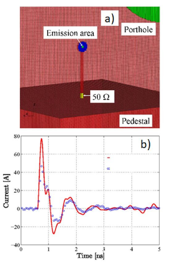
Laser produced electromagnetic pulses                                                                                                                  3

             discusses the known techniques of mitigation of EMP ef-                                target or the size of the ionized zone accumulating the charge
             fects, experience accumulated on several high-power laser                              in a dielectric target. The capacitance of metallic targets of
             facilities and possible applications of EMP. Finally, Section 5                        a centimeter size is of the order of 0.4 pF. As the maximum
             concludes the review with a figure presenting the measured                             voltage is limited by the hot electron temperature, Φ . Th /e,
             EMP levels on different laser facilities.                                              the maximum accumulated charge can be estimated as Q e '
                                                                                                    Ct Th /e. The accumulated charge is also limited by the
                                                                                                    available laser pulse energy E las , Q e . e ηlas E las /Th , with
             2. Physics of EMP generation
                                                                                                    ηlas the laser conversion efficiency to hot electrons. Thus,
                                                                                                    the accumulated charge depends on both laser pulse energy
             2.1. Target polarization
                                                                                                    and intensity. It is typically in the range from a few nC
             The principal source of electromagnetic emissions is charge                            to a few µC depending on the laser energy and focusing
             separation and target polarization under the action of a laser                         conditions[10, 30] . It may attain values of a few tens of µC
             pulse. Strong laser fields ionize the atoms and create a                               in experiments with petawatt-class lasers[14] , where more
             plasma, which expands from the target surface. As the laser                            energetic electrons can be generated. These values of the
             pulse interacts essentially with electrons, the plasma is far                          charge have been confirmed in Ref. [13], which reported
             from thermodynamic equilibrium. The electrons are heated                               on the first systematic measurements of the electric charge
             and accelerated by the laser pulse and their average energy is                         accumulated on the target in the laser energy range of 0.01–
             much higher than that of ions. Moreover, a relatively small                            0.1 J. An increase in the accumulated electric charge with the
             proportion of the electrons are accelerated to energies much                           lateral size of the target has been reported also in Ref. [35].
             above the average and may leave the target[28] , thus charging                            It is important to know how fast the charge is accumulated
             it positively. The total number of escaping electrons is de-                           and how long it can be maintained on the target. The
             fined by dynamical competition between the high energy of
                                                                                                    temporal characteristics of the current define the spectral
             escaping electrons and the electric potential increase due to
                                                                                                    domain of emission and the field amplitude. There are two
             electron escape[29] . We describe numerical methods for the
                                                                                                    characteristic times defining the charge accumulation: the
             charge evaluation in Sections 2.3 and 2.4. Here, we present
                                                                                                    laser pulse duration and the cooling time of hot electrons.
             qualitative estimates for metallic targets irradiated with laser
             intensities ∼1018 –1020 W·cm−2 . The characteristic electron                           The hot electrons are primarily cooled through collisions
             energies are in the MeV domain and correspondingly the                                 with atomic electrons in the target. The cooling time of
             targets are charged to MV potentials in order to confine the                           MeV electrons on a solid target is on the ps timescale. For
             remaining electrons[30, 31] .                                                          example, the cooling time of a 1 MeV electron, tcool , is
                The target potential Φ cannot be much larger than the                               10 ps in aluminum, 3 ps in copper and 2 ps in tantalum[36] .
             characteristic energy (hot electron temperature) Th of laser                           So, for sub-ps laser pulses, the electron ejection time de-
             heated electrons, Φ . Th /e, where e is the elementary                                 pends weakly on the laser pulse duration but mainly on the
             charge. A more accurate relationship depends on the electron                           laser pulse energy and the target material. In contrast, the
             energy distribution, target material and other interaction                             discharge time depends on the size of the target and the
             characteristics. The hot electron temperature can be assimi-                           impedance of the target support: in the simplest case, it is a
             lated with a ponderomotive energy of electrons oscillating in                          stalk ls ∼ 5–10 cm long and a few mm in diameter. The time
             the laser field[32] ,                                                                  of propagation of a signal across a target of a size dt ∼ 1 cm
                                                                                                    is 1t ' dt /2c ∼ 16 ps. So, for a pulse duration shorter than
                                        Th ' (γ0 − 1)m e c2 ,                             (1)       a few ps, the target charging process is temporally separated
                             q                                                                      from the discharge process. In contrast, for longer laser pulse
             where γ0 = 1 + a02 /2 is the relativistic factor of an                                 durations, the charge is not accumulated on the target, but
             electron oscillating in the laser field, a0 = eE 0 /m e ω0 c is the                    rather the target potential is established by a balance between
             dimensionless laser vector potential, E 0 is the laser electric                        the rate of electron ejection and the amplitude of the return
             field amplitude, ω0 is the laser frequency, m e is the electron                        current through the stalk to the ground. This discharge time
             mass and c is the velocity of light. The formula for γ0                                ls /c is of the order of 100 ps and sets the upper limit of the
             is written for a linearly
                                 q      polarized laser pulse. For circular                         laser pulse duration that is prone to produce intense EMPs.
             polarization, γ0 = 1 + a02 .                                                           It also explains why the problem of EMP emission is of
                In order to evaluate the charge accumulated on the target,                          particular importance for ps and sub-ps pulses and why it has
             the target capacity Ct must be known[33] . It can be approx-                           attracted less interest in experiments with longer, ns pulses.
             imated by the capacitance of a conducting disc of diameter                             Nevertheless, since EMP fields scale with both laser intensity
             dt , Ct ' 40 dt [34] , where 0 is the vacuum dielectric permit-                      and energy, they are still very serious threats for nanosecond
             tivity. In our case, dt could be a transverse size of a metallic                       high-energy facilities.

Downloaded from https://www.cambridge.org/core. 30 Sep 2020 at 16:02:23, subject to the Cambridge Core terms of use.
4                                                                                                                                      F. Consoli et al.

       2.2. Mechanisms of electromagnetic emission                                             the interaction chamber or striking the chamber walls[9, 42] .
                                                                                               Similar secondary electromagnetic emissions can be created
       2.2.1. Terahertz emission                                                               by the flash of hard X-rays emitted from the laser–target
       Electromagnetic emissions are produced at all stages of                                 interaction zone or from nuclear explosions in air[43, 44] .
       the laser–target interaction. However, we are specifically                              Depending on the laser pulse duration, these secondary
       interested in the emissions that are produced during the                                emissions could be in a broad frequency range from THz in
       electron ejection process, that is, during and after the laser                          the case of sub-ps laser pulses, but also in the GHz and MHz
       pulse on the characteristic time of electron cooling, which                             domains for longer, ns laser pulses. They excite the reso-
       is about a few ps. The corresponding frequency is in the                                nant electromagnetic modes and scattered radiation in the
       domain going down from 1 THz. The amplitude of EMPs                                     experimental chamber that may live up to µs timescales[45] .
       in that domain is highly significant, and these frequencies                             However, because of a strong divergence of the electron
       are the most damaging for electronic circuits. Two principal                            bunch and X-rays, the intensity of these secondary emissions
       sources of EMP emission can be identified: the first is related                         is much weaker than that of the primary one. The electric
       to the ejected electrons and the second to the return current.                          field induced in an electro-optical crystal by an ejected
          In the case of ps or sub-ps laser pulses, the duration of                            electron bunch was measured in references[46, 47] .
       electron ejection tej ' dt /c corresponds to an electron bunch
       of millimetrical length: lej ' dt . Ejection of such a bunch can                        2.2.2. Gigahertz emission
       be considered as the creation of a dipole with an effective                             Emissions in the domain of frequencies lower than 30–
       charge Q e . According to the Larmor formula, the power                                 100 GHz are produced on a timescale longer than 30–100 ps
       of emission is proportional to the second derivative of the                             and related to the relaxation of the charge accumulated on
       dipolar moment[34, 37] ,                                                                the target during the laser pulse interaction. Let us consider
                                                                                               an example of a metallic target in the form of a disc of
                                               µ0                                              diameter dt ∼ 1 cm, supported by a metallic stalk of length
                                     PE =          | D̈|2 ,                          (2)
                                              6π c                                             ls ∼ 5–10 cm and diameter ds ∼ 1 mm, attached to the
                                                                                               ground plate. Assuming a laser pulse duration in the ps
       where µ0 is the vacuum magnetic permeability. The dipolar                               range or shorter, a charge Q e is set on the target before
       moment D increases quickly and nonlinearly during the first                             the discharge current is formed. The current flows from
       picosecond from zero to ∼Q e lej , when the bunch separates                             the target through the stalk to the ground. Assuming that
       from the target. After that, the charge is constant and                                 the charge is distributed more or less homogeneously over
       the length of the dipole increases almost linearly as the                               the target surface, the current duration can be estimated as
       bunch flies away from the target. Consequently, the second                              the time needed to propagate the charge across the target,
       derivative of D is significant only during the ejection time.                           1t ' dt /c. The current pulse duration has been measured
       Assuming that the dipolar moment varies quadratically with                              in experiments of several groups[13, 48–50] . The current pulse
       time, the total electromagnetic energy emitted during the                               of a duration 1t and intensity Jt = Q e /1t flows down the
       electron ejection can be estimated as                                                   stalk, reflects from the ground and returns to the target. It
                                                                                               thus oscillates along the stalk.
                                         Z0 2         Q 2e                                        The system of a target and a stalk attached to the ground
                            ETHz '             Qe '        ,                         (3)
                                        6π tej      1.5πCt                                     is an example of a linear antenna. It may emit signals
                    √                                                                          over a broad frequency range depending on the temporal
       where Z 0 = µ0 /0 ' 377 , the vacuum impedance. This                                  shape of the feed-in current, but in our case of interest
       simple formula shows that the emitted energy is of the same                             for a current pulse length that is shorter than the antenna
       order (a few times smaller) as the electrostatic energy of                              length, the characteristic wavelength of emission is four
       the charged target. It is proportional to the square of the                             times the stalk length, λemp = 4ls [51] . This could be
       electric charge and inversely proportional to the electron                              qualitatively understood by knowing that the ground plate
       ejection time tej . This latter dependence explains why the                             can be considered as a plane of symmetry, and the system
       dipolar emission is the most important for the sub-ps laser                             ‘a stalk on the ground’ is electrically equivalent to a straight
       pulses, where it may attain a level on the order of tenths                              wire of length 2ls with the charges +Q e and −Q e attached
       of a percentage of the laser energy. Observation of this                                to its ends at the initial moment of time, that is, to a dipole
       terahertz emission has been reported in Refs. [37–41]. In                               of length 2ls . Starting from t = 0, the charges propagate
       agreement with the dipolar mechanism of electromagnetic                                 along the wire, meet at the center at time t = ls /c and
       field generation, the terahertz emission was observed in the                            invert the motion at time t = 2ls /c. Consequently, the
       plane perpendicular to the direction of electron emission.                              period of a full oscillation is 4ls /c, which corresponds to the
          In addition to the EMP emission during the hot electron                              wavelength 4ls and the principal frequency ωs = π c/2ls .
       ejection, the bunch of ejected electrons may induce sec-                                For the stalk length ls = 7 cm, the oscillation period is 1 ns,
       ondary dipoles while flying near sharp metallic objects in                              which corresponds to the GHz frequency range. In fact,

Downloaded from https://www.cambridge.org/core. 30 Sep 2020 at 16:02:23, subject to the Cambridge Core terms of use.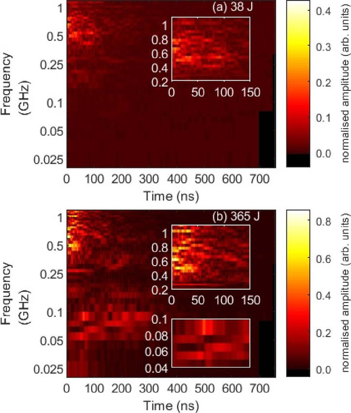
Laser produced electromagnetic pulses 5
the radiation field is created at particular moments when
the current pulse enters the stalk and inverts its motion.
Correspondingly, in the temporal domain, the radiation field
consists of a sequence of pulses of duration equal to the
current duration[51] . In the Fourier domain, the spectrum
of emission contains the higher harmonics, in addition to
the main frequency. The emission spectrum depends on the
details of the current temporal shape, but qualitatively the
number of harmonics can be estimated as a ratio of the main
period to the current pulse duration, Nh ∼ 4ls /dt .
Assuming there are no other objects in the near-field, the
intensity of EMP emission at the main frequency of the target
support structure can be estimated using the formula for a
linear half-wavelength antenna[34] :
2.44
PE = Z 0 |Jωs |2 . (4)
8π
The current entering in this expression is the Fourier com-
ponent of the total current at the emission frequency. As
the current pulse length ∼dt is much smaller than the
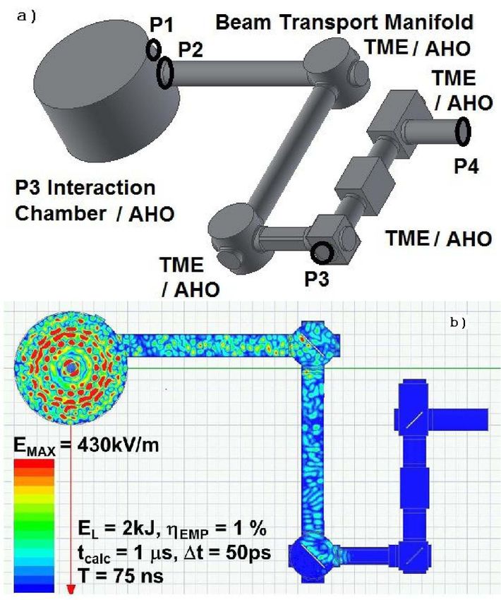
stalk length, that component can be estimated as Jωs ∼ Figure 1. Schematic of charged target (a) standing alone and (c) connected
to the ground. Spectra of EMP emission (b) from the free standing target
Jt /Nh = Q e c/4ls . Consequently, the emission power and (d) from the target connected to the ground.
is proportional to the square of accumulated charge and
inversely proportional to the square of the stalk length. It
is therefore beneficial for suppressing EMP to increase the pulse intensity and energy. That fact has been reported in
stalk length, as it reduces both the emission power and the several experiments[13, 52] .
emission frequency at the same time. In reality, the stalk The role of the conducting stalk in EMP emission can
emission is not monochromatic; it is quite broad because the be demonstrated in the following numerical experiment
emission time is just a few periods – the current is rapidly performed with the electromagnetic code SOPHIE[53] (see
dissipated because of resistance losses. The total emitted Section 2.4 for further details). Let us consider a conducting
energy in the GHz domain can be estimated as a sum of all disc of diameter ds = 1 cm as the target. At time t = 0 under
harmonics: the effect of a short and intense laser pulse, some electrons
2.44c c were ejected and a positive charge Q e is created in the small
EGHz ' Z 0 Q 2e Nh ' 0.1 Z 0 Q 2e . (5) spot in the target center; see Figure 1(a). Calculation of the
32πls dt
electromagnetic emission from such a target gives a broad
Comparing Equations (5) and (3), we conclude that the spectrum shown in Figure 1(b). It extends to frequencies
emitted energy in the GHz domain is of the same order of above 10 GHz comparable to the disc resonance frequency
magnitude as in the THz domain. Nevertheless, the GHz c/4ds = 7.5 GHz. The emission completely changes
emission attracts much more attention because of its much if the target is connected to the ground with a stalk as
stronger effect on electronic devices. shown in Figure 1(c). The emission spectrum is shown in
Equation (5) for the emitted energy can be also obtained Figure 1(d) for the stalk length ls = 7 cm. It is dominated
directly from the Larmor formula (Equation (2)) in the time by the resonance frequency f s = c/4(ls + ds /2) = 1 GHz
domain[51] . The emission is created when charge is entering accompanied by a much weaker peak at the disc resonance
the stalk. The corresponding dipole moment increases from frequency.
zero to the value Dt ' Q e c1t. Then, the emitted power Figure 2 shows dependence of the radiated magnetic field
reads: (µ0 c/6π )Q 2e /1t 2 . Accounting also for the emission H calculated numerically at a distance R = 15 cm as a
from the mirror charge and multiplying for the emission time function of electric current in the stalk J and evaluated from
1t, the total emitted energy can be estimated as EGHz ' Equation (4). The good agreement confirms the usefulness of
(c/3π dt )Z 0 Q 2e in good agreement with Equation (5). Re- a simplified analytical approach for quick evaluation of the
calling also that the accumulated charge is proportional to radiated field. Linear dependence of the radiated field on the
the hot electron temperature, which varies approximately current indicates the way to proceed for the EMP mitigation:
as the square root of the laser intensity (Equation (1)), we one has to reduce the current through the stalk by increasing
conclude that the EMP energy is proportional to the laser the discharge time.
Downloaded from https://www.cambridge.org/core. 30 Sep 2020 at 16:02:23, subject to the Cambridge Core terms of use.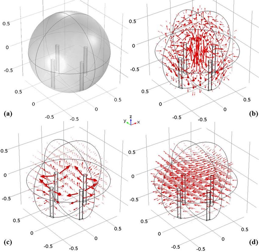
6                                                                                                                                                  F. Consoli et al.

                                                                                               Figure 3. Scheme of target charging in the case of short-pulse interaction
                                                                                               with a thick solid target. Hot electrons are created in the laser focal spot (red
       Figure 2. Dependence of the radiated magnetic field at distance R = 15 cm               zone). They spread in the target over a distance comparable to the mean free
       from the antenna shown in Figure 1(c) on the current in the stalk: 1 –                  path (gray zone). The electrons escaping in vacuum create a spatial charge
       calculated numerically and 2 – evaluated from Equation (4).                             and prevent low-energy electrons from escaping. Electrons with energies
                                                                                               higher than the surface potential escape from the target and create a net
                                                                                               positive charge at the surface. Reprinted with permission from Ref. [13].
                                                                                               Copyright 2014 by the American Physical Society.
          The intensity of GHz emission can be affected by chang-
       ing the stalk material and/or reducing the velocity of the
       propagation of the current. By using a dielectric stalk,                                by a different, long-pulse laser (14 ns, 205 mJ, 1064 nm).
       one increases its resistance and consequently reduces the                               The same effect was described in Ref. [57] in the case of
       return current[52] . Another possibility is to increase the                             glass and copper targets.
       effective time of current propagation between the target and                               Among multiple sources of this emission, we mention
       the ground by making the stalk in a form of a spiral. For a                             the secondary polarization charges induced by ejected elec-
       spire radius r and a pitch h, the speed of current propagation                          trons on the conducting parts of the chamber[9, 42] , emission
       along the spiral axis vk is reduced by a factor 2πr/ h, and                             from a toroidal current circulating in the expanding plasma
       consequently the major emission frequency hc/4ls r is not                               plume[58] and the plasma recombination after the end of
       compatible with the antenna length. The emission power                                  the laser pulse[59] . As observed in the previous paragraph,
       is expected to decrease by a factor (2r/ h)2 . The authors                              further contributions to the GHz range can come from
       of Ref. [52] reported suppression of the emitted signal by a                            charged particles emitted from the target inducing secondary
       factor of 30 by using a plastic spiral compared to a straight                           dipoles on metallic objects, and from X-rays acting on
       aluminum stalk (see Section 4.1 for more details).                                      surfaces of objects exposed to the radiating interaction.
          This simple analysis also explains why the ps laser pulses
       are much stronger emitters in the GHz domain, compared
       to the ns pulses. The former accumulate a big charge for a                              2.3. Modeling of the electron emission
       short period of time and discharge it in a short and intense
       current pulse. In contrast, the latter induce a relatively                              Ejection of energetic electrons is identified as the dominant
       weak continuous current and consequently a much weaker                                  source of target charging. This process is shown schemati-
       emission. The authors of Ref. [54] present the measurements                             cally in Figure 3, assuming that the target size is larger than
       of the EMP emission in the GHz domain produced with                                     the hot electron mean free path. The target charging process
       laser pulses of intermediate duration of 300 ps, which is                               can be described by the following steps.
       shorter than the period of the return current oscillations but
       longer than the electron cooling time. Consequently, electron                             (1) The laser pulse deposits its energy at the target surface.
       ejection persists during the whole driving laser pulse and the                                It is partially transferred to the hot electrons with
       emission spectrum extends to lower frequencies in the MHz                                     conversion efficiency ηlas . Their energy distribution
                                                                                                     can be approximated by a Maxwellian function with
       domain, but its intensity decreases with frequency[45, 55] .
                                                                                                     the effective temperature Th given by Equation (1).
          The EMP signal can be significantly enhanced if a long
       and a short laser pulses interact with the same target. In                                (2) The electrons accelerated in the backward direction
       Ref. [56], the emission caused by ultrashort (38 fs, 35 mJ,                                   are ejected from the target in vacuum, thus creating
       800 nm) laser pulse ablation at atmospheric pressure of a                                     an initial potential Φ near the target surface. This
       metal target was observed to be enhanced by an order of                                       potential confines the major part of escaping electrons
       magnitude due to a preplasma generated on the same target                                     in the Debye layer and returns them back to the target.

Downloaded from https://www.cambridge.org/core. 30 Sep 2020 at 16:02:23, subject to the Cambridge Core terms of use.
Laser produced electromagnetic pulses                                                                                                                                     7

               (3) The hot electrons are accelerated in the forward direc-
                   tion and propagate outside the laser focal spot. Their
                   diffusion is dominated by the elastic collisions with
                   the target ions, and collisions with the target electrons
                   define their cooling time. It is of the order of a few ps
                   for common metals such as aluminum or copper.

               (4) Some of the scattered hot electrons are ejected from
                   the target as long as their energy remains higher
                   than the electrostatic potential Φ. This process is
                   accompanied by the increase of the potential, and
                   it stops as the maximum electron energy equals the
                   potential. Thus, the processes of the potential buildup
                   and electron cooling define the maximal time of the
                   target charging.

               (5) The deficit of electrons in the laser spot is compen-                            Figure 4. Dependence of the target charge Q e on the laser energy and
                                                                                                    the pulse duration for the laser spot radius of 6 µm, the absorption fraction
                   sated by the return current of cold electrons, so the                            ηlas = 40% and laser wavelength of 0.8 µm. The dashed white rectangle
                   charged zone expands radially over the target surface                            shows the domain explored in the experiment. Reprinted with permission
                   approximately with the light velocity. The hot electron                          from Ref. [60]. Copyright 2015 by the American Physical Society.
                   cloud expands also but more slowly with the drift
                   (thermal) electron velocity. For targets thinner than
                                                                                                    temperature with an additional factor ξ depending on the
                   the hot electron mean free path, the electron emission                           ratio of the hot electron Debye radius to the radius of the hot
                   takes place also from the rear side[36] .                                        electron cloud on the target surface, eφth = Th ξ (λ Dh /Re ),
                                                                                                    and also on the ratio of the Debye length to the target
               The theoretical model developed in Refs. [13, 36, 60, 61]
                                                                                                    thickness. The electrostaticRpotential φ E is proportional to
             describes the target charge buildup with two equations: the
                                                                                                    the escaped current Je = e ge dε distributed over the disc
             hot electron distribution function f eh (ε, t) and the electric
                                                                                                    on the target surface with the radius increasing with the light
             potential Φ(t). The distribution function varies in time due
                                                                                                    velocity:
             to three processes:
                                                                                                                                         t                   Je (t 0 )
                                                                                                                                     Z
                                                                                                                              1
                           ∂t f eh =   Slas (ε, t) − τee
                                                      −1
                                                         f eh    − ge (ε, t),             (6)                    φ E (t) =                   dt 0                                 .   (7)
                                                                                                                             2π 0   0              Re   (t ) + c(t
                                                                                                                                                           0             − t 0)
             production of the hot electrons with rate Slas , cooling of                            This model is realized numerically as a Fortran 90 program
             hot electrons in the electron–electron collisions with char-                           ChoCoLaT2.f90[36] and is available on request. This pro-
             acteristic time τee and ejection of electrons from the target                          gram computes the time evolution of the electron cloud
             surface with rate ge depending on the potential Φ. The                                 parameters, the evolution of the ejection current distribution
             production rate is assumed to be a Maxwellian function                                 and the evolution of the two contributions to the potential
             of energy, with the hot electron temperature depending                                 barrier. These three important parts of the model are closely
             on the laser intensity according to Equation (1). This                                 interrelated.
             approximation is in agreement with the observations of                                    Figure 4 shows the dependence of the accumulated charge
             energetic electrons produced in laser–plasma interaction and                           on the laser pulse energy and duration calculated with the
             empirical scaling[32, 62] . The function is normalized to the                          model. One can distinguish two different regimes of target
             linear production of electrons by the laser: ηlas E las /Th tlas .                     charging. First, an almost complete hot electron ejection
             The electron cooling time can be described by analytical                               takes place in the case where Th & eΦ, where the target
             expressions[63] or taken from the tables[64] . The radius of
                                                                                                    Rcharge
                                                                                                       R     can be approximated as Q e ' eNe . Here Ne =
             the emission zone Rh increases with time according to the                                   Slas dt dε is the total number of hot electrons. Second,
             hot electron velocity from the minimum value equal to the                               there is a quasi-stationary regime where the laser pulse
             laser focal spot to the maximum value equal to the electron                             duration is longer than the hot electron cooling time. In this
             mean free path.                                                                         case, the current of ejected electrons is equal to Je = Q e /tlas .
                The electric potential is represented as a sum of the                               Between these two limits there is a thermal regime, where all
             thermal potential created by the electrons in the Debye                                the features of the model play an important role.
             layer near the target surface and the positive charge left on                             This model demonstrates dependence of the charging
             the target surface by escaped electrons: Φ = φth + φ E .                               process on the laser and target parameters. The number and
             The thermal potential is proportional to the hot electron                              energy of hot electrons depend primarily on the absorbed

Downloaded from https://www.cambridge.org/core. 30 Sep 2020 at 16:02:23, subject to the Cambridge Core terms of use.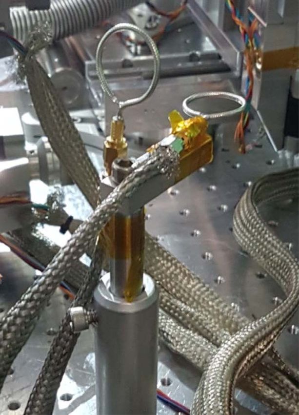
8                                                                                                                                                       F. Consoli et al.

                                                                                               Figure 6. Target charge Q e in nC calculated from the model as a function
       Figure 5. Target charge Q e in nC calculated from the model as a function of
                                                                                               of the absorbed laser energy and the target diameter for the pulse duration
       the absorbed laser energy and the focal spot diameter for the pulse duration
                                                                                               of 1 ps, the focal spot diameter of 10 µm, wavelength of 0.8 µm and an
       of 1 ps, wavelength 0.8 µm and an insulated and laser size target. There is
                                                                                               insulated target. There is a threshold on the target diameter below which the
       an optimal spot diameter for the target charging.
                                                                                               target charging becomes dependent on it.

       laser energy, intensity and focusing conditions. The con-                               longer than the ejection process, the target can be considered
       ventional estimate of hot electron average energy, given in                             as isolated from the ground. Otherwise, the neutralization
       Equation (2), may be altered by effects such as stochas-                                must be accounted for in the model as it impacts the value
       tic heating[65] and direct laser acceleration under suitable                            of the electrostatic potential. This effect is described by
       conditions[66] . With increase of laser pulse energy and target                         modifying Equation (7) as follows:
       size, more electrons are ejected. Numerical simulations
       and experiments discussed in Section 4 show that the target                                                                  t           Je (t 0 ) − Jn (t 0 )
                                                                                                                                Z
                                                                                                                         1
       charge is increasing with the laser energy according to a                                            φ E (t) =                   dt 0                           .    (8)
                              α with index α varying between 1 and
                                                                                                                        2π 0   0              Re (t 0 ) + c(t − t 0 )
       power law Q e ∝ E las
       0.5 depending on intensity. Increase of the laser focal spot                            If the neutralization time is much shorter than the electron
       and of the pulse duration for a given absorbed pulse energy                             ejection time, one can equalize the ejection and neutral-
       results in a decrease of laser intensity and, consequently,                             ization currents, Je ≈ Jn , and set φ E = 0. This case
       of the number of ejected electrons. Dependence of the                                   of a fully grounded target applies to sufficiently long laser
       number of ejected electrons could be more complicated                                   pulses. Here the ejection current is weak, and it does not
       in experiments where laser defocusing is accompanied by                                 produce oscillations responsible for EMP generation in the
       a variation of absorption due to nonlinear laser–plasma                                 GHz domain.
       interaction[67] . However, laser focal spot and pulse duration                             The target size also has an impact on the charging process.
       have very different consequences if one increases them too                              Let us consider a cylinder with its axis aligned with the
       much while keeping the laser energy unchanged. As the laser                             laser. It is characterized by thickness etar and radius rtar .
       intensity is reduced, there are more electrons produced with a                          The target radius defines its charge capacitance. Reduction
       smaller energy. Then, the thermal barrier is also reduced and                           of the target radius and capacitance results in an increase
       the electrostatic potential φ E dominates the barrier. As the                           of the electrostatic potential that has a strong impact on the
       latter is not directly related to laser intensity and the electron                      charging process by reducing the final value of Q e . Figure 6
       energy decreases with the laser intensity, the ejected charge                           shows the dependence of the target charge on radius rtar .
       Q e is reduced as the laser intensity decreases. Therefore,                             The radius where the target can be considered as infinite
       there is an optimal intensity for the most efficient charging                           depends on the laser energy. This effect was also investigated
       process, as shown in Figure 5. This was confirmed in                                    analytically in Ref. [61] and experimentally in Ref. [69].
       Ref. [68] by comparing the theoretical estimates made with                                 The target thickness can vary from large values where
       ChoCoLaT2.f90 with experimental data.                                                   hot electrons never reach the rear side to very small values
          We discuss now generation of the neutralization current                              ∼10 µm, which are comparable with the Debye length of the
       Jn and introduce the characteristic time of electron ejection                           hot electron cloud λ Dh . The target thickness has two effects
       tej as a maximum between the electron cooling time and                                  on the charging process. First, if the hot electron mean
       the laser pulse duration. The electron ejection time can be                             free path is larger than the target thickness, the electrons are
       compared to the time of propagation of the neutralization                               trapped inside the target and recirculate; the current increases
       current along the stalk, tn = ls /c. If the neutralization time is                      because of ejection, which takes place from both sides of the

Downloaded from https://www.cambridge.org/core. 30 Sep 2020 at 16:02:23, subject to the Cambridge Core terms of use.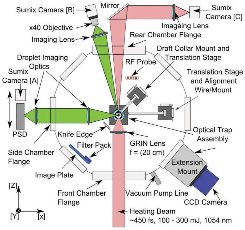
Laser produced electromagnetic pulses                                                                                                               9

             target. Second, the thermal potential φth has a lower value,                              Numerical simulations reported in Ref. [13] were per-
             if λ Dh > etar , which results in a current burst. However,                            formed with the laser intensity 2 × 10¹⁸ W · cm−2 , laser
             these two effects are mitigated by the electrostatic part of the                       wavelength of 0.8 µm, pulse duration of 50 fs and focal
             potential barrier, which increases with the current according                          spot radius of 4 µm. According to the PIC simulations,
             to Equation (7). Globally, in thin targets the ejected charge                          about 40% of the incident laser energy was transferred to
             increases by a factor that depends on the laser energy and                             hot electrons in the copper target with a temperature Th '
             duration: by 2 times for short pulses of 1 J and by 5 times                            250 keV. The PIC simulation box was however too small
             for short pulses of 0.1 kJ. This has been demonstrated in                              to distinguish between the escaped and trapped electrons.
             Ref. [36]. The charge accumulation has been compared with                              The Monte Carlo simulation shows that about 35% of the
             experimental data in Refs. [36, 68].                                                   hot electrons injected in the target are scattered back into
                The target crystalline structure also affects the electron                          the vacuum. Their energy is 2–3 times larger than the hot
             mean free path and consequently the accumulated electron                               electron temperature.
             charge. In experiments with targets made of different                                     The current decreases by an order of magnitude in 2 ps
             allotropes of carbon in Ref. [70], it was found that the highly                        after the laser pulse and the emission zone is limited effec-
             ordered lattice structure of diamond at temperatures of the                            tively by the radius of 10 µm. These numbers are consistent
                                                                                                    with the expected lifetime of hot electrons and their mean
             order of 1–100 eV results in longer electron mean free path
                                                                                                    free path. The emission continues for a few tens of ps and
             and suppression of electron beam filamentation compared to
                                                                                                    the emission zone extends to a few mm, but more than 90%
             less ordered forms of carbon.
                                                                                                    of the total charge was emitted in the first 2 ps. At that
                In the study described in Ref. [71], a laser pulse (1 ps,
                                                                                                    moment, the target is charged to a potential of about 200 kV
             100 J) irradiated 200 µm thick CH targets doped with
                                                                                                    compatible with the hot electron temperature.
             different titanium (Ti) concentrations at the XG-III laser
                                                                                                       A Monte Carlo transport code describes single particle
             facility. The observed EMP emission was related to the
                                                                                                    motion in matter, but it does not account for collective
             hot electrons ejected from the target surface in the forward                           effects and self-consistent electromagnetic fields. There-
             direction. The EMP intensity increased by a factor of 2                                fore, it cannot describe the electromagnetic emission. The
             when doping increased from 1% to 7% and then slightly                                  fourth stage of EMP modeling was performed with a large-
             decreased. This behavior is explained by an increase of the                            scale electromagnetic PIC code SOPHIE[53] describing the
             target conductivity and laser absorption due to the doping,                            collective motion of electrons in free space with prescribed
             which favored hot electron emission in the forward direction.                          boundary conditions on the surfaces. The electron emission
                                                                                                    from the target was described with current density calculated
                                                                                                    using a Monte Carlo code as shown in Figure 7(a). The
             2.4. Numerical modeling of the EMP emission
                                                                                                    simulation was performed in a box of volume of a few
                                                                                                    mm3 and for a time of 40 ps. Figure 7(b) shows the
             Because of the large disparity of temporal scales, the process
                                                                                                    current of ejected electrons recorded at the other surface of
             of electron emission needs to be simulated in several sub-
                                                                                                    the simulation box at a distance of 1 mm from the target
             sequent steps by using different numerical tools. First, the
                                                                                                    surface. This distance is much larger than the hot electron
             hot electron production during the interaction of an intense
                                                                                                    Debye length, and consequently it describes the electron
             laser pulse with a solid target depends strongly on the quality
                                                                                                    bunch that escaped from the target. As it follows from
             of the target surface at the moment of laser pulse arrival.
                                                                                                    three simulations with different target sizes, the escaped
             It may be modified by the laser prepulse and affect the
                                                                                                    electron charge does not depend on the target size. It
             absorption of the main laser pulse. The preplasma formation                            has a rising part of 2–3 ps duration, corresponding to the
             and its expansion from the solid target surface is described                           separation of the electron bunch from the target, and a slowly
             with a radiation hydrodynamic code on the ns timescale.                                decreasing part, corresponding to the tail of the electron
             Secondly, as the main laser pulse interaction with the plasma                          bunch. The delay of 3.5 ps between the ejected and recorded
             and hot electron generation are kinetic processes, they are                            currents corresponds to the time of electron propagation
             simulated in detail with a relativistic particle-in-cell (PIC)                         from the target to the recording surface. The electromagnetic
             code. This fully kinetic simulation is however limited to a                            emission is generated in the rising part of the current, and it
             characteristic time of the order of 1 ps and to a spatial size                         corresponds to the THz pulse described in Section 2.2.1.
             of a few tens of microns. Moreover, the electron collisions                               The GHz emission was described in additional numerical
             are described in a simplified manner. For these reasons, at                            simulation with the code SOPHIE on much larger temporal
             the third step, the electron distribution calculated with a PIC                        and spatial scales and by taking into account the boundary
             code is transferred to a Monte Carlo particle transport code                           conditions in the whole experimental chamber, including
             describing the propagation of hot electrons in the solid target,                       the target, stalk and all other elements. Figure 8(a) shows
             their collisions and secondary reactions. It provides the                              the simulated volume of 1 m3 and position of the target
             number and the energy distribution of the escaped electrons.                           and the stalk. In this case, the spatial resolution of 1 mm

Downloaded from https://www.cambridge.org/core. 30 Sep 2020 at 16:02:23, subject to the Cambridge Core terms of use.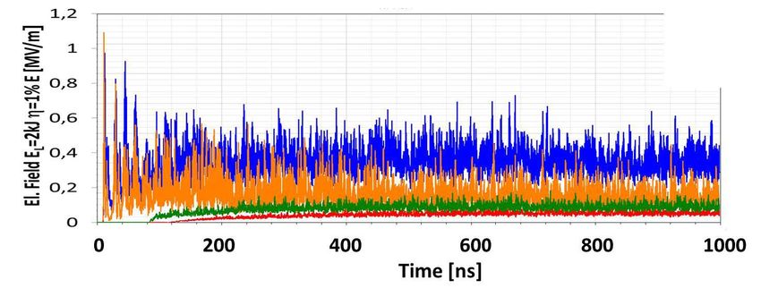
10                                                                                                                                                F. Consoli et al.

       Figure 7. (a) Time dependence of the current density of electrons emitted
       backward from the target surface at different distances from the laser axis
       obtained in the Monte Carlo simulation. (b) Time dependence of the electric
       current of escaped electrons collected at a distance of 1 mm from the
       target. Three simulations with the target radii 2.5, 5 and 7.5 mm are shown.
                                                                                               Figure 8. (a) Simulation of the current at the bottom of the target assembly.
       The dashed line shows the ejection current obtained from the Monte Carlo
                                                                                               Calculation with the SOPHIE code: the target radius is 5 mm, the laser pulse
       simulation. Reprinted with permission from Ref. [13]. Copyright 2014 by
                                                                                               energy is 80 mJ and the pulse duration is 50 fs. The current is collected at an
       the American Physical Society.
                                                                                               effective 50  resistance. (b) Comparison of the calculated waveform (red
                                                                                               solid line) with the experimental data (blue dots). Reprinted with permission
                                                                                               from Ref. [13]. Copyright 2014 by the American Physical Society.
       is poorer than in the previous case but the simulation was
       run for a longer time of a few ns, and the return current
       collected at a resistance placed near the ground plate is                               possible experimental conditions. The simplified model is
       shown in Figure 8(b). The duration of this current is more                              less precise; it may differ by a factor 2–3 and thus provides a
       than 100 ps, much longer than the ejection current and the                              more qualitative estimate, but it is much faster and might be
       current of ejected electron bunch shown in Figure 7(b).                                 sufficient for a quick evaluation of the EMP amplitude.
       As explained in Section 2.2.2, the duration of the return
       current is proportional to the target size. Correspondingly,
                                                                                               2.5. Intense transient fields due to deposition of charged
       the amplitude of the return current is more than one order
                                                                                               particles
       of magnitude smaller than the current of the ejected electron
       bunch.                                                                                  Charge emitted by intense laser–target interactions can be
          A similar numerical model of EMP generation caused by                                efficiently deposited onto objects present within the chamber
       electron emission is described in Ref. [72]. In this case,                              and, in particular conditions, may give rise to the generation
       the EMP associated with emitted electrons was computed                                  of very large transient electric fields, even rather far from the
       with a specially designed code EMPIC-2D. Dependence                                     interaction point. A scheme of this phenomenon is shown in
       of the EMP signal on the target size, laser pulse duration                              Figure 9.
       and intensity is consistent with the results presented in this                             This was demonstrated for energetic petawatt-range laser–
       review.                                                                                 matter interactions[73] using the Vulcan Petawatt laser at
          The numerical simulations discussed so far confirm the                               the Rutherford Appleton Laboratory (RAL), operating at
       theoretical estimates discussed in Section 2.2 and the major                            a wavelength of 1054 nm[74] . Pulses of ∼1 ps duration
       results of the simplified model presented in Section 2.3.                               were focused by an off-axis parabolic mirror at an intensity
       While the detailed numerical simulations provide a rather                               above 1020 W · cm−2 on parylene-N foil targets at normal
       accurate quantitative description of the emission process,                              incidence. The experimental setup is shown in Figure 10.
       they are time-consuming and cannot be performed for all                                 Thomson spectrometers were used to detect particles emitted

Downloaded from https://www.cambridge.org/core. 30 Sep 2020 at 16:02:23, subject to the Cambridge Core terms of use.
Laser produced electromagnetic pulses 11
Figure 9. Scheme of the field induced due to charge deposition on one plate
of a capacitor–collector setup. The system is initiated by a flow of energetic
particles from a pulsed laser-driven source. Reprinted from Ref. [73] under
Creative Commons license.
Figure 11. (a) VDDOT signal detected by the D-dot probe in shot #29;
(b) time-gated normalized spectrogram of the signal. The origin of the
timescale was set at the moment when the EMP signal reaches the D-dot
probe. Reprinted from Ref. [73] under Creative Commons license.
Figure 10. Top-view scheme of the vacuum chamber; the laser (red beam)
is focused on a thin-foil target by an off-axis parabola mirror. Reprinted
from Ref. [73] under Creative Commons license.
by the target normal sheath acceleration (TNSA) process[75]
in forward (TS2 and TS3) and backward (TS1) directions
with respect to the incoming laser. The focusing parabola
consisted of a 110 mm thick, 650 mm diameter glass sub- Figure 12. (a) Component of the electric field normal to the D-dot
strate with a 620 mm diameter silver front surface, placed at ground plane measured in shot #29. (b) Comparison of several single-shot
measurements of the electrical field component normal to the D-dot ground
1.8 m from the target. plane.
The AD-80D(R) D-dot differential electric field sensor[76]
(3 dB bandwidth up to 5.5 GHz) (see Section 3.2.1) was
placed behind the parabola mirror, which provided good by laser–plasma interaction, with a fast rise followed by
isolation from direct particle and ionizing electromagnetic an envelope with an exponential decay. The time-resolved
radiation fluxes from the target. It was at ∼2.2 m overall spectrogram of this signal (see Section 2.6.2) is given in
distance from origin, with its sensitive direction (normal to Figure 11(b), and shows that indeed a low-frequency com-
its ground plane): û = 0.12x̂ + 0.87 ŷ + 0.49ẑ. The position ponent (LFC) is present only in the 40–80 ns interval,
and orientation were set for efficient protection against initial while the high-frequency component (HFC) is present from
direct ionizing radiation due to the laser–matter interaction. the beginning over a larger time interval and has a broad
The BIB-100G balun (250 kHz–10 GHz bandwidth) was spectrum up to 6 GHz.
connected to its terminals for a high rejection of common- Through a process of accurate cable frequency-domain de-
mode disturbances. Details of the measurement methods for embedding (see Section 3.1) and numerical time integration,
this specific experiment are supplied in Section 3.2.4. the component of the applied electric field normal to the D-
For shot #29 (269 nm target thickness, 386 J laser energy dot ground plane was determined, as shown in Figure 12(a).
and 4.8 × 10²⁰ W · cm−2 intensity), the resulting VDDOT Both the LFC and HFC can be clearly seen. In particular,
signal stored by the oscilloscope is shown in Figure 11(a). the broadband HFC appears as a modulation with respect
At first sight, the trace looks like a classical EMP generated to the LFC; it has a maximum peak-to-peak amplitude
Downloaded from https://www.cambridge.org/core. 30 Sep 2020 at 16:02:23, subject to the Cambridge Core terms of use.12 F. Consoli et al.
1E HFC-pp ∼ 172 kV/m, visible in the (0, 30) ns time interval
and gradually decreases with time. This is the classical form
of EMP due to a laser–plasma interaction. Concerning the
LFC, the field increases over the interval (30, 93) ns time to
1E LFC ∼ 600 kV/m. The field rise is delayed with respect
to the laser pulse, and can be readily associated with charges
reaching the focusing parabola and depositing on its surface.
Neutralization of the deposited charge on the parabola can
occur later in time due to either particles of opposite charge
arriving at later times or charge relaxation processes with
a time constant governed by the parabola structure and its
Figure 13. Comparison between experimental D-dot measurements from
support. shot #29 and PIC simulations of electric fields at the D-dot position, in the
Figure 12(b) shows the comparison of electric field pro- û and x̂ directions. The origin of the timescale is here set at the moment
files obtained by D-dot measurements when shooting with of laser–target interaction, and the #29 measurement was thus time-shifted,
with respect to Figures 11 and 12, by the EMP propagation time from target
similar laser energy on targets made of the same plastic but of
to D-dot probe. Reprinted from Ref. [73] under Creative Commons license.
different thicknesses. Higher fields are generated for targets
with smaller thickness. Indeed, this is also the condition to
of emitted electrons with energies of a few eV surrounding
achieve more accelerated particles, also at higher energy, in
it and leave a transient superficial positive charge. On a
a classical TNSA scheme[75] . The rise of the electric field
slightly longer timescale, MeV-range relativistic electrons
depends on the shot and for the thinnest target (shot #16) are expected to deposit a negative charge on the same
occurs earlier with respect to the others, as expected for more surfaces, since secondary-electron emission at those energies
energetic protons. These considerations are confirmed by the
is smaller than unity[73] . These two processes operate in
spectrum of protons detected by the TS1 spectrometer in the
opposite directions, and it is not trivial to estimate the electric
backward direction for the shots #16 and #29[73] . fields due to their superimposition. Indeed, no associated
Proof-of-principle numerical simulations were performed field was observed during the early moments shown in
by CST Particle Studio three-dimensional (3D) PIC code Figure 12(a), perhaps because it was hidden by the con-
to get a suitable description of the field development due temporary presence of the HFC due to classical EMP. This
to charged particle dynamics in the considered setup. The was the reason why in the PIC simulations only one low-
parabola was modeled as a thin silver layer on a thick energy component was considered for the electrons, which
glass cylinder, mounted on a stainless steel annular holder. was sufficient to give a good phenomenological description
Secondary-electron emission and superficial charge deposi- of the process observed experimentally.
tion were computed on all surfaces. Space-charge effects
were also calculated, but the overall bunch charge was kept
to low values to minimize them. For each particle species, 2.6. Methods of description for EMP signals
emission was uniformly distributed within a θ = 20◦ angle
to target normal, and also uniform in velocity within a given 2.6.1. Modal structure of the fields in the vacuum chamber
particle kinetic range. The duration of EMP fields extends over a time much longer
The optimization process was performed to get a suit- than the laser pulse. The average dimensions of a vacuum
able qualitative fit to the experimental data of D-dot probe chamber used in experiments of laser–matter interaction is
shown in Figure 12(a). An energy range (0.774, 2.68) MeV up to a few meters, and thus the microwave electromagnetic
and 35 nC overall charge was determined for protons, and waves undergo multiple reflections on the objects usually
(9.40, 34.7) keV and 7.5 nC for electrons. Figure 13 shows present within the chamber, and especially on its walls,
a comparison of the normalized D-dot measurements and floor and roof. Consequently, the quasi-modal structure of
simulation results for shot #29 at the same position, for both fields in such a resonant cavity is settled out after tens of
x and u (the sensitive D-dot axis normal to its ground plane) reflections, corresponding to an overall transient time of a
components of the electric field. Even with this rather simple few hundreds of ns. The electromagnetic field inside the
model, a close agreement is reached, and the optimized vacuum chamber can be mathematically represented as the
proton energy range is in good correspondence with the most weighted sum of an orthogonal set of proper modes[77–79] :
energetic part of spectrum measured by TS1[73] . +∞ M−1 +∞
In experiments of this type, intense UV, X and γ bursts X X X
E= Ai Ei + Ai0 Ei0 + Bi si ,
were produced at the moment of laser–target interaction,
i=1 i=1 i=1
together with beams of relativistic electrons. The electro- (9)
+∞ P−1 +∞
magnetic contribution is capable of generating photoioniza-
X X X
H= Ci Hi + Ci0 Hi0 + Di gi ,
tion on any exposed surface, and can thus create a layer i=1 i=1 i=1
Downloaded from https://www.cambridge.org/core. 30 Sep 2020 at 16:02:23, subject to the Cambridge Core terms of use.You can also read