A Liquid Hydrogen Target for the MUSE Experiment at PSI
←
→
Page content transcription
If your browser does not render page correctly, please read the page content below
A Liquid Hydrogen Target for the MUSE Experiment at PSI
P. Roya , S. Corsettia , M. Dimonda , M. Kima , L. Le Pottiera , W. Lorenzona,∗, R. Raymonda , H. Reida , N. Steinberga ,
N. Wuerfela , K. Deitersb , W.J. Briscoec , A. Golossanovc , T. Rostomyand,b
a Randall Laboratory of Physics, University of Michigan, Ann Arbor, MI 48109-1040, USA
b Paul Scherrer Institut, CH-5232 Villigen, PSI, Switzerland
c Department of Physics, The George Washington University, Washington, D.C. 20052, USA
d Rutgers, The State University of New Jersey, Piscataway, New Jersey 08855, USA
Abstract
arXiv:1907.03022v1 [physics.ins-det] 5 Jul 2019
A 280 ml liquid hydrogen target has been constructed and tested for the MUSE experiment at PSI to investigate the
proton charge radius via simultaneous measurement of elastic muon-proton and elastic electron-proton scattering. To
control systematic uncertainties at a sub-percent level, strong constraints were put on the amount of material surrounding
the target and on its temperature stability. The target cell wall is made of 120 µm-thick Kapton® , while the beam
entrance and exit windows are made of 125 µm-thick aluminized Kapton® . The side exit windows are made of Mylar®
laminated on aramid fabric with an areal density of 368 g/m2 . The target system was successfully operated during a
commissioning run at PSI at the end of 2018. The target temperature was stable at the 0.01 K level. This suggests a
density stability at the 0.02% level, which is about a factor of ten better than required.
Keywords: Liquid hydrogen target, muon beam, MUSE, elastic scattering
1. Introduction requirements for the target system [4] include not only a
LH2 cell, but also an empty cell for studying background
Until recently, the proton charge radius had been well generated from the target walls and a thin, solid target
established at rp = 0.8768(69) fm [1] from electronic- for precision vertex reconstruction and detector alignment.
hydrogen spectroscopy and electron-proton scattering To facilitate rapid switching between the LH2 and empty
measurements. However in 2010, a novel experiment using target cells, and to accommodate the MUSE spectrometer
muonic-hydrogen spectroscopy [2] determined the proton geometry, the target system has to be movable in the verti-
charge radius to be rp = 0.84184(67) fm. This roughly cal direction. Furthermore, large thin vacuum windows on
five-standard-deviation difference has become known as either side of the beam are needed to cover the very large
the proton radius puzzle [3]. solid angle subtended by the detectors while introducing
The MUon Scattering Experiment (MUSE) [4], located minimal amounts of multiple scattering.
in the PiM1 area of the Paul Scherrer Institute (PSI) in
A LH2 target system that met all experimental and
Switzerland, is part of a suite of experiments that aim
safety requirements was designed and fabricated in close
to resolve the proton radius puzzle. MUSE attempts to
collaboration with Creare Inc, and then installed and tho-
determine the proton charge radius through simultaneous
roughly tested at PSI. This paper describes the major com-
measurements of muon-proton and electron-proton elastic
ponents of the target apparatus and presents data demon-
scattering cross sections with high precision. The exper-
strating the successful operation of the LH2 target.
imental kinematics cover three beam momenta of about
115, 153, and 210 MeV/c and scattering angles in the
range of 20◦ − 100◦ , corresponding to Q2 of approximately
0.002 (GeV/c)2 − 0.08 (GeV/c)2 , the range of the form fac- 2. Target System
tor with greatest sensitivity to the radius [4].
At the heart of the experiment is a liquid hydrogen
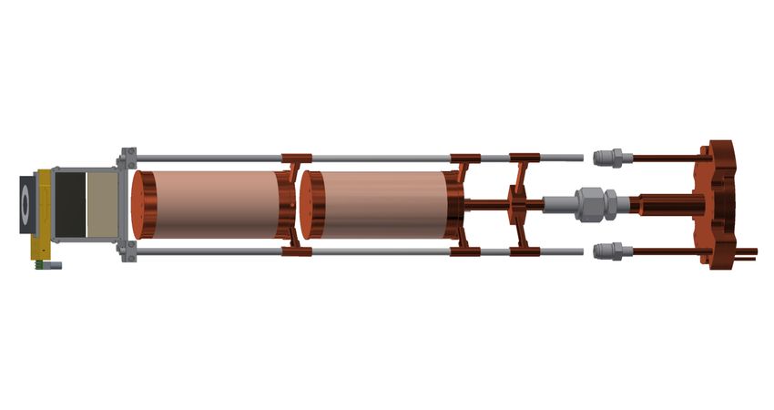
(LH2 ) target that needs to provide stable density and suf- The MUSE target system, shown in Fig. 1, consists of
ficient cooling power to minimize uncertainty in target a target ladder with a variety of targets, a cryocooler and
length in order to allow cross section measurements at the condenser assembly that liquefies the hydrogen gas, a vac-
sub-percent level. Since hydrogen is highly explosive, spe- uum chamber that houses the target ladder, a lifting mech-
cial precautions had to be taken to ensure safe handling. anism that allows fast switching of the target cells, a gas
Driven by the science needs for MUSE, the experimental handling system, and a slow control system that regulates
temperature and the hydrogen gas flow in and out of the
∗ Corresponding author target cell.
Preprint submitted to NIMA July 9, 2019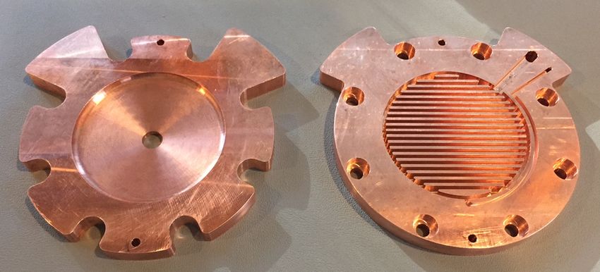
cold head
guide rods
(3x)
bellows positioning
scales (3x)
leadscrew (3x)
vacuum
beam entrance chamber
window
targets
66 cm
side exit lifting plate
window (2x) feedthrough bellows
collar
x,y,z translation
stage stepper
beam motor
pump port & exit
observation window
window (not
shown)
target
stand
base plate
19 cm
Figure 1: Left Panel: Schematic view of the trapezoidal vacuum chamber and the lifting assembly mounted on a support stand. The vacuum
chamber is 66 cm high. Right Panel: Close-up view of the lifting assembly components that facilitate the vertical motion of the target ladder.
The bellows outer diameter is 19 cm.
2.1. Target ladder cap. Each sensor is a 100 Ω Allen Bradley carbon resistor
The target ladder, shown in Fig. 2, can be moved in and driven at 20 mA. One Lakeshore Cernox® thin film resis-
out of the particle beam in the vertical direction. The main tance cryogenic temperature sensor and one (50 Ω, 50 W)
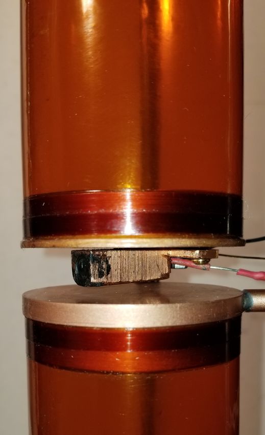
target, shown in Fig. 3, is a 280 ml LH2 cell assembled from cartridge heater are mounted on the outer face of the bot-
a 6 cm inner diameter Kapton® cylinder and copper end tom end cap (see Fig. 3). The temperature sensor, the
caps that provide strength and stability to the Kapton® level sensors, and the heater are all monitored and con-
wall. It is operated at a temperature of 20.65 K and a trolled by the slow control system described in Sec. 2.6.
pressure of 1.1 bar. Below the LH2 target cell is an empty target cell which is
The cell wall is made with four wraps of a single sheet identical to the LH2 cell. It is used to subtract background
of 25 µm-thick Kapton® foil which is 130 mm wide and originating from the Kapton® walls, and to a lesser extent
758 mm long. The four wraps are glued together using from the copper end caps of the LH2 cell. A small orifice
Stycast 1266 epoxy. The thickness of the epoxy layers is on the top end cap of the empty cell connects its inner
controlled to achieve a total cell wall thickness of about space to the vacuum that surrounds the target ladder.
120 µm. To form a strong glue joint between the end A 1 mm-thick solid target is attached below the empty
caps and the cylinder, each copper end cap reaches 1 cm cell to allow for precise vertex reconstruction, and to aid
into the Kapton® cylinder. This leads to a cell with a in detector alignment. It is split into two parts, with
11 cm high, thin Kapton® wall to minimize background the polyethylene (CH2 ) target mounted above the carbon
from scattering from the copper end caps into the detec- (C) target. A beam focusing detector, installed just be-
tors. The cells are further reinforced by first gluing two low the carbon target, is used to check beam focusing in
9 mm-wide Kapton® strips, followed by two 5 mm-wide the target region. The beam focusing detector, shown in
Kapton® strips over the glue joints between the cylinder Fig. 4, consists of three scintillators mounted in a horizon-
and the end caps, as shown in Fig. 3. Burst tests performed tal line, with 1 cm separation. The scintillators are made
at room temperature have consistently shown that the cells of 2 × 2 × 2 mm3 plastic, and are connected by light guides
can withstand pressures of over 3.8 bar. This provides a to silicon photomultipliers (SiPMs) [6]. The beam focus-
higher safety factor than the factor of three required by ing detector can also be used to map out the vertical beam
the PSI safety group. profile by moving the assembly in the vertical direction.
The target cell has two level sensors (with one serving Just below the beam focusing detector is an optical tar-
as a backup) mounted on the inner surface of the top end get. This target is viewed by a camera to determine the
2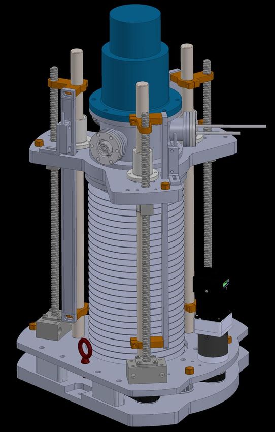
6.7cm
                                                     supply/vent tubes
                condenser

                                                     alignment
                                                     tubes (2x)

                                                     fill/return tube with
                                                     VCR connection

          precision stainless
      steel support tubes (2x)

                                            13.7cm

                 LH2 target cell

                                                     1.5cm
                                            13.7cm

              empty target cell

                                                                                 Figure 3: A photograph of the LH2 cell (top) and empty cell (bot-
                                                     1.0cm                       tom). The cell is reinforced with two wide and two narrow Kapton®
                                            7.0cm

                    CH2 target                                                   strips glued to the end caps. Also shown is the cartridge heater,
                     C target                                                    containing one 50 Ω, 50 W resistor, and one Cernox® temperature
                                                       1.0cm                     sensor (partially hidden) attached to the end cap of the LH2 cell.
       beam focusing detector
                     bull’s-eye
                    empty space

                                                                                 2.2. Cryocooler and condenser assembly
Figure 2: CAD drawing of the target ladder connected to the con-
denser showing the target positions (LH2 cell, empty cell, CH2 tar-
                                                                                    The CH110-LT single-stage cryocooler from Sumitomo
get, C target, empty space) as well as the location of the beam
focusing detector and the optical “bull’s-eye” target. A total verti-            Heavy Industries Ltd was selected for refrigeration.1 It has
cal displacement of 34 cm is required to attain all positions. Note              a cooling power of 25 W at 20 K which is sufficient to cool
that the superinsulation wrap and the copper braids are omitted for              down and fill the target cell in approximately 2.6 hours.
clarity.
                                                                                    The condenser, shown in Fig. 5, is made of two copper
                                                                                 plates soldered together to enclose a cavity with an inter-
                                                                                 nal surface area of 346 cm2 for collecting and condensing
horizontal position of the target ladder inside the vacuum                       hydrogen gas. The top plate has a series of copper fins
chamber to better than 0.1 mm, using pattern recognition.                        to provide the large surface area for condensing hydrogen,
The lowest target position, noted as “empty space” posi-                         while the bottom plate contains a shallow, cone-shaped
tion in Fig. 2 is used to study background events arising                        floor that guides the liquefied hydrogen to the fill tube in
from interactions with materials in the experimental setup                       the center of the bottom plate. The fill tube is made of
aside from the target cell.                                                      reinforced copper with a 8 mm inner and a 20 mm outer
   The target ladder is connected to the condenser through                       diameter and forms the sole connection between the con-
the hydrogen fill-and-return tube which contains VCR®                            denser and the target ladder. Boiled-off hydrogen from
metal gasket face seal fittings for ease of changing ladders.                    the target cell returns to the condenser cavity through the
Two thin tubes, made of precision stainless steel, support                       same tube.
the empty cell, the carbon target and the beam focusing                             The condenser is bolted to the cryocooler cold head.
detector. They are positioned so as to minimize inter-                           Apiezon N, a very low vapor pressure vacuum grease, is
ference with scattered particles. The support tubes also                         used to establish good thermal contact between the cold
maintain alignment between the LH2 cell and the empty                            head and the condenser. In order to maintain constant
cell to within a few hundred microns. Cooling of the empty                       temperature in the target cell, the condenser has two iden-
cell is achieved through copper braids connected to the                          tical 25 Ω, 100 W heater circuits and two Cernox® tem-
LH2 cell.                                                                        perature sensors which are controlled by the slow control
   The heat load on the target from the particle beam [4]                        system (see Sec. 2.6). One heater circuit and one tempera-
is less than 10 µW. The approximately 1.4 W radiation                            ture sensor are for regular operation while the others serve
heat load from the vacuum chamber on the target cells                            as backups.
is reduced to about 130 mW by wrapping 10 layers of alu-
minized Mylar® superinsulation around the target ladder                             1 Sumitomo was chosen over Cryomech partly because similar cry-
and condenser. Heat load on the target due to conduction                         ocoolers are commonly used at PSI and because Sumitomo has a
is negligible.                                                                   service center in Darmstadt, Germany.

                                                                             3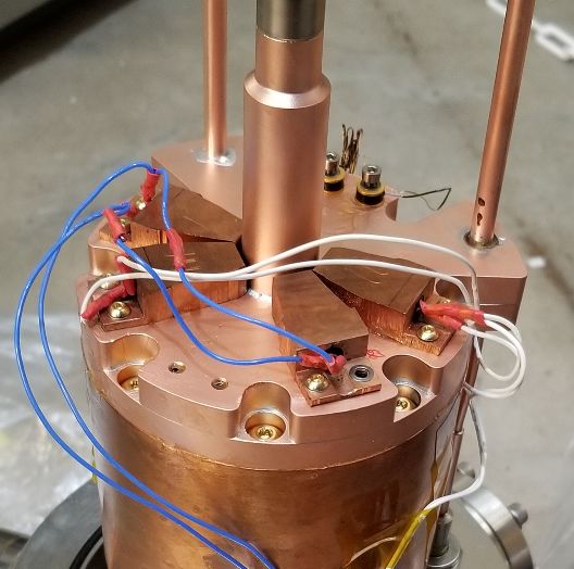
65 mm                                    The beam entrance window has a 7 cm diameter clear
                                                                               aperture for the 2 cm FWHM beam. It is made of
                        3 light guides
                                                 3 SiPMs
                                                                               a 125 µm-thick aluminized Kapton® sheet, a material
                                                                               known for its excellent radiation resistance. The two
                                                                               rectangular side exit windows are each 337 mm wide and
                                                                               356 mm high and cover the azimuthal angle range θ ∈
                                                                               [20◦ , 100◦ ] on either side of the beamline. The polar angle
                                                                               φ coverage of each window is [−45◦ , 45◦ ] from the target
                                                                               center at θ = 60◦ . These unusually large vacuum win-
                      scintillators              air channels                  dows are covered with a sailcloth fabric which is made of
                                                                               Mylar® laminated on aramid fabric with an areal den-
Figure 4: A schematic view of the beam focusing detector. Beam po-             sity of 368 g/m2 [7]. This material is stronger than avail-
sitions are measured with three small scintillators that are connected         able Kapton® foil and can withstand the pressure differ-
by light guides to SiPMs.
                                                                               ence between the atmospheric pressure outside and the
                                                                               10−4 mbar pressure inside the vacuum chamber. Each
   A feedthrough collar with three ports is connected to the                   window assembly consists of a frame that is glued to the
chamber top. Two of the ports hold electrical feedthroughs                     aramid fabric. The Mylar® side of the sailcloth seals onto
for target temperature control and the beam focusing                           the vacuum chamber with an o-ring. GEANT4 simulations
detector, and one port provides the fluid feedthrough. The                     of the multiple scattering introduced by the window ma-
electrical feedthrough for the beam focusing detector pro-                     terial have shown an angular resolution of 18.2 mrad, just
vides both low voltage to the SiPMs and signal readout for                     below the experimental requirement of 19 mrad. Exposure
each of the three SiPMs. The fluid feedthrough contains                        of the window material to the 120 GeV/c proton beam at
the stainless steel tubing for hydrogen gas inlet and outlet.                  Fermilab has demonstrated that it is radiation resistant
                                                                               to at least a factor of 10 more than the total integrated
                                                                               particle flux expected in MUSE.3 The beam exit window,
                                                                               which is 78 mm wide and 356 mm high, is much narrower
                                                                               than the two side exit windows and therefore suitable for
                                                                               125 µm-thick aluminized Kapton® foil. Its frame was de-
                                                                               signed to strengthen the vacuum chamber.
                                                                                  Due to the space constraints, a single port on the bot-
                                                                               tom of the vacuum chamber acts as the pumping port and
                                                                               the view port for the camera system that monitors the hor-
                                                                               izontal position of the target ladder. The vacuum chamber
                                                                               is mounted on a three-legged stand made of 80/20 T-slot
Figure 5: A photograph of the bottom (left) and top (right) con-               aluminum extrusions. The stand is bolted to the plat-
denser plates. The top plate has a series of copper fins to provide a
large surface area for condensing hydrogen.
                                                                               form that supports the entire MUSE experiment, and has
                                                                               translation mechanisms to adjust the chamber position in
                                                                               all three directions.
2.3. Vacuum chamber
   The vacuum chamber, shown in the left panel of Fig. 1, is                   2.4. Lifting assembly
66 cm high [5]. Due to the considerable space constraints                         The target system has a lifting mechanism, shown in the
imposed on the target system by the detectors, its hor-                        right panel of Fig. 1, to switch between the LH2 and empty
izontal dimensions are limited to a circular area with a                       target cells about twice a day without suffering the time
diameter of 48 cm. The chamber is made of stainless steel                      delay of filling and emptying the cell at that frequency. It
plates with a thickness of 9.5 mm. Based on structural                         also eliminates the need to worry about changes in den-
stress analysis using the ANSYS simulation software, this                      sity due to orthohydrogen to parahydrogen conversion[10],
wall thickness provides at least a factor of two safety factor                 which can take several days[11].
from the yield point. The chamber has a trapezoidal shape                         The vertical movement is achieved by using three lead
so that the two large side exit windows are both flat2 and                     screws which are driven by a cogged timing belt and step-
parallel to the detector planes.                                               per motor system. Three guide rods keep the lifting plate
                                                                               centered and restrict movement to the vertical direction.
   2 Although it was preferred to have a vacuum chamber with a
                                                                               In order to obtain a true and independent vertical location
single, continuous exit window that covers the entire θ scattering
angle range between −100◦ and +100◦ , no solution was obtained
                                                                               of the lifting plate, a magnetic position scale is attached
that did not produce pleats in the vacuum window material in the
middle of the acceptance. Those pleats lead to inhomogeneities which
are difficult to simulate and to large multiple scattering for particles          3 The total integrated particle flux for MUSE is expected to be

passing through them.                                                          3 MHz × 1 year = 1014 particles.

                                                                           4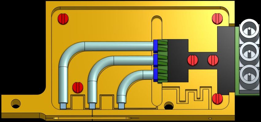
Figure 6: A schematic layout of the gas handling and vacuum systems is shown, with the legend of the symbols on the right. The flexible
lines accommodate vertical movement of the ladder. The gauge pressures of the relief valves RV-1, RV-2 and RV-CT, that serve as passive
safety valves for the gas system, are indicated in the diagram. Note, that RV-IN is not a primary safety valve.

to each guide rod at three equally spaced radial positions.           approximately 310 liters of hydrogen gas are needed to fill
A large, edge-welded bellows [8] with an inner diameter of            the LH2 target. Safe disposal of the hydrogen gas from
15.2 cm accommodates the required vertical movement of                the target cell is achieved by releasing the gas through a
34 cm to attain all target positions.                                 hydrogen vent line which sends the gas above the PiM1
                                                                      area and towards the top of the experimental hall. There
2.5. Gas handling and vacuum system                                   is no need to use a dedicated hydrogen exhaust line that
                                                                      directs the gas outside of the experimental hall because
    A schematic layout of the gas flow is shown in Fig. 6. A          the approximate 0.3 m3 of hydrogen gas released into the
10 liter gas bottle containing about 1,000 gas liters of com-         experimental hall is much smaller than the huge volume
pressed hydrogen supplies 99.999% pure hydrogen gas to                of the experimental hall.
the target. The gas bottle is placed just outside the PiM1
experimental area. The gas flow is controlled using pneu-
matic valves which are operated via a slow control system.               The vacuum system consists of scroll and turbo pumps
Safety valves PV-3 and PV-4, which are normally-open                  with a pumping speed of 60 l/s, as well as valves and a
type pneumatic valves, are set to open at 0.4 bar above               vacuum control system that is based on the Simatic HMI
the operating pressure of 1.1 bar to ensure safe venting of           system from Siemens. The layout of the pumps and valves
the target cell in case of accidental loss of compressed air          is shown in Fig. 6. The turbo pump is backed by a scroll
or an electric power failure. Overpressure mechanical relief          pump with a buffer volume to increase the lifetime of the
valves RV-1 and RV-2, which act as backup valves for the              scroll pump. This is achieved by turning off the scroll
pneumatic valves, are connected in parallel to the safety             pump while the buffer volume is being filled to a pressure
valves and operate independently of the slow control sys-             of 0.15 mbar. Once that pressure is reached, the scroll
tem. They are set to open if the pressure in the supply or            pump turns back on and empties the buffer volume. This
the vent lines exceeds 0.7 bar above the operating pressure.          procedure reduces operation of the scroll pump by about
    The supply line and target are purged with hydrogen               90%. The same scroll pump is also used to pump out
before starting a cooldown. The purge process involves                the supply line, and the target cell for purging. To avoid
filling the target with hydrogen gas to 1.1 bar (absolute)            triggering a false fire alarm, the exhaust outlet of the scroll
while the chamber is under vacuum, then pumping it out                pump is above the target-chamber chimney which houses
using a scroll pump. Once the purge process is completed,             a hydrogen gas sensor.
                                                                  5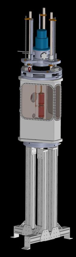
2.6. Target slow control and safety systems
   The entire target system is monitored and controlled
by a slow control system from National Instruments [9]
with a LabView graphical user interface. This includes
the pneumatic valves of the gas system, the cryocooler
compressor, the heater on the target cell, the pumping
station, as well as several safety features such as interlocks
and alarms. The slow control system communicates with
a Lakeshore Model 336 temperature controller, which reg-
ulates the temperature of the copper condenser, and thus
of the target cell. To maintain constant temperature, the
Lakeshore temperature controller reads the condenser tem-
perature with a Cernox® temperature sensor and drives                     Figure 8: Results of the first hydrogen cooldown performed in the
the cartridge heater circuit, shown in Fig. 7, in a feedback              PiM1 experimental hall at PSI covering the initial 3 hours. The red
                                                                          (blue) curve shows temperature versus time for the condenser (target
loop. The temperature of the LH2 cell is monitored by                     cell) as it is cooled down. The dashed green curve indicates the
a Cernox® temperature sensor and displayed by the slow                    resistance of the level sensor inside the top end cap of the target cell.
control system. The slow control system also controls the                 At about 2.3 hours, the liquid level appears to reach the top end cap.
cartridge heater which is mounted on the outer face of the                The target cell is full about 2.5 hours after cooldown start.
bottom end cap, as shown in Fig. 3. This heater is used
to speed up the evaporation of liquid hydrogen during the                 it is cooled down from room temperature to 21 K in about
target shut down process.                                                 40 minutes. The blue curve shows the temperature of the
                                                                          bottom of the target cell as it is cooled down by liquid hy-
                                                                          drogen dripping from the condenser until it reaches liquid
                                                                          hydrogen temperature. The dashed green curve indicates
                                                                          the resistance of the level sensor inside the top end cap
                                                                          of the target cell. The increase in the resistance is due to
                                                                          improved cooling of the sensor resistor as it is first in con-
                                                                          tact with and then immersed in LH2 . The sharp increase,
                                                                          followed by a constant resistance after about 2.6 hours in-
                                                                          dicates that the target is “full”.

Figure 7: Photograph of two heater circuits, each consisting of two
50 Ω, 50 W cartridge heaters connected in parallel, and two Cernox®
temperature sensors attached to the bottom of the condenser, which
is pictured upside down here. Each cartridge heater is glued and
housed inside a copper block which is bolted to the condenser to
ensure good thermal contact.

  Hydrogen gas sensors placed in chimneys above the gas
handling panel and the target chamber sound alarms if
                                                                          Figure 9: Results of the first hydrogen cooldown performed in
a hydrogen leak is detected. Furthermore, these sensors                   the PiM1 experimental hall at PSI covering the time period from
are interlocked to PV-6 to automatically cut-off hydrogen                 2 − 78 hours. It takes about 6 hours for the target cell temperature
supply in case a leak is detected.                                        to stabilize. The jitter level in the condenser readout channel (red
                                                                          curve) was reduced significantly at hour 31 by increasing the signal
                                                                          readout averaging time from 1 to 5 seconds.
3. Target Operation
                                                                             Figure 9 shows data from the same cooldown as in Fig. 8.
  After passing all safety reviews, the MUSE LH2 target                   It takes about 6 hours for the target temperature to stabi-
was filled with liquid hydrogen and ran steadily for over                 lize. Note that due to the low beam power and the con-
three days. Figure 8 shows the first hydrogen cooldown.                   siderable cooling power provided by the cryocooler, it is
The red curve shows the temperature of the condenser as                   not possible to tell when beam was on or off during that
                                                                      6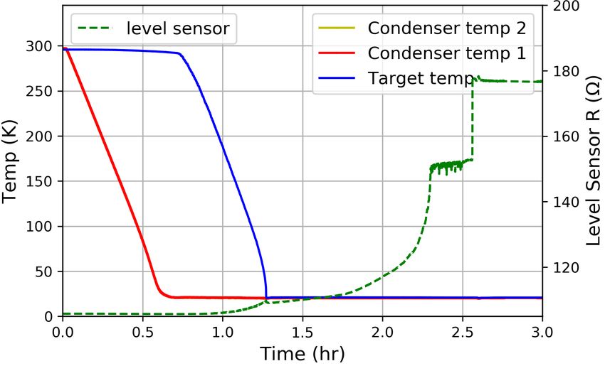
time period. Figure 10 shows the variation of the target                     his specific suggestions for how to build the Kapton® tar-
temperature at the target cell operating temperature of                      get cells. We also thank Klaus Kirch, Malte Hildebrandt
20.67 K during the time period displayed in Figure 9. It                     and Stefan Ritt (all PSI) for their their help and feedback
demonstrates that the target cell temperature was con-                       with the target safety procedures and documentation, and
stant at the 0.01 K level over the entire 72 hour period.                    the PSI vacuum group for providing the vacuum system,
The 20.67 K target temperature corresponds to an oper-                       and especially Pascal Mayer for his design and assembly of
ating pressure of about 1.1 bar4 and a target density of                     the system. We acknowledge Manuel Schwarz and Thomas
0.070 g/cm3 .                                                                Rauber (both PSI) for their continuous help and support,
                                                                             and Steffen Strauch (University of South Carolina) for
                                                                             his help with target simulations. W.J. Briscoe gratefully
                                                                             acknowledges the helpful conversations with Greg Smith
                                                                             (JLab), Kurt Hanson (MAXlab) and Andreas Thomas
                                                                             (MAMI) during the target R&D stage. This work was sup-
                                                                             ported in part by US National Science Foundation grants
                                                                             1614456, 1614850, 1614938, 1649873 and 1807338. The ini-
                                                                             tial conceptual design was supported by US Department
                                                                             of Energy grant DE-SC0012485.

                                                                             References
                                                                              [1] P.J. Mohr, B.N. Taylor, and D.B. Newell, CODATA Recom-
                                                                                  mended Values of the Fundamental Physical Constants: 2006,
                                                                                  Rev. Mod. Phys. 80, (2008) 633.
Figure 10: Histogram of target temperature values measured during
                                                                              [2] R. Pohl et al., The size of the proton, Nature 466, (2010) 213.
hours 6 − 78. The shape of the distribution is purely Gaussian with
                                                                              [3] R. Pohl, R. Gilman, G.A. Miller, and K. Pachucki, Muonic hy-
a mean of 20.67 K and a standard deviation of 0.01 K.
                                                                                  drogen and the proton radius puzzle, Annu. Rev. Nucl. Part.
                                                                                  Sci. 63, (2013) 175.
                                                                              [4] R. Gilman at al., Technical Design Report for the Paul Scher-
                                                                                  rer Institute Experiment R-12-01.1: Studying the Proton “Ra-
4. Conclusions                                                                    dius” Puzzle with µp Elastic Scattering, arXiv:1709.09753v1
                                                                                  [physics.ins-det].
   A liquid hydrogen target was built for the MUSE ex-                        [5] The vacuum Chamber was designed by Creare Inc. and built by
                                                                                  Sharon Vacuum Co Inc.
periment at PSI which measures the proton charge ra-                          [6] The scintillators are made of 2×2×2 mm3 Saint-Gobain BC404
dius with high precision via both elastic muon-proton and                         plastic and are connected by 3 mm-diameter Saint-Gobain BCF-
electron-proton scattering. In order to take advantage of                         98 SC light guides to Hamamatsu S13360-3050PE silicon pho-
the unique opportunities afforded by the PiM1 beamline                            tomultipliers. Each SiPM is operating at 55.5 V, consuming less
                                                                                  than 0.2 µA; this means the total power is below 33.3 µW.
at PSI, and to control for systematic uncertainties at the                    [7] The two large vacuum windows are covered with a sailcloth
sub-percent level, strong constraints were put on the ma-                         fabric by Dimension-Polyant, called D-P C785, which is made
terial budget around the target and on its temperature                            of Mylar® laminated on aramid fabric with an areal density of
stability. Data collected from a commissioning run at PSI                         368 g/m2 .
                                                                              [8] The large, edge-welded bellows was manufactured by Metal-
demonstrated that the target was run stably at a temper-                          Flex® Inc. It has part number 75060-9W/FLGES with an outer
ature of (20.67 ± 0.01) K over several days. This tempera-                        diameter of 19.1 cm and an axial stroke of 30.5 cm.
ture stability suggests a liquid hydrogen density stability                   [9] The slow control system is based on the Crio-9035 system from
                                                                                  National Instruments. All safety related tasks are run on a built-
of 0.02% once equilibrium concentration of parahydrogen
                                                                                  in FPGA. The graphical interface is based on the LabVIEW
and orthohydrogen has been reached [11].                                          Real-Time Module from National Instruments.
                                                                             [10] J.W. Leachman, R.T. Jacobsen, S.G. Penoncello, and
                                                                                  E.W. Lemmon, Fundamental Equations of State for Parahy-
Acknowledgments                                                                   drogen, Normal Hydrogen, and Orthohydrogen, J. Phys. Chem.
                                                                                  Ref. Data 38, (2009) 721.
                                                                             [11] The saturated liquid density variation between parahydrogen
  We would like to thank Sheldon Stokes for leading the                           and orthohydrogen at 20 K is about 0.1%. The equilibrium con-
Creare Inc. team to help us design and build the target                           centration of orthohydrogen and parahydrogen changes from
system, and Walter Fox (Indiana University) and Dany                              room temperature, where it is nearly 75% orthohydrogen and
Horovitz (consultant to Hebrew University of Jerusalem)                           25% parahydrogen, to above 99% parahydrogen and below 1%
                                                                                  orthohydrogen at 20 K [10]. Note that it can take several days
for their initial conceptual designs. We are grateful to Ben                      to achieve equilibrium.
van den Brandt (PSI) for his many useful discussions and

   4 The target was operated at 20.67 K along the liquid/gas satu-

ration line, which corresponds to a pressure of very close to 1.1 bar.
For details see https://webbook.nist.gov/chemistry/fluid/.

                                                                         7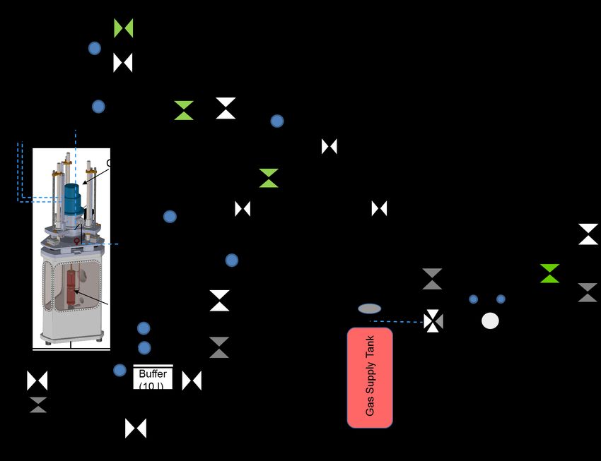
You can also read