AL3800 Operation Manual | EN - Directory ...
←
→
Page content transcription
If your browser does not render page correctly, please read the page content below
Operation Manual | EN

AL3800
Coreless linear servomotors

5/21/2021 | Version: 3.6

Documented motors – AL38xx

             Documented motors – AL38xx
Linear servomotor   Speed     Peak force for 3 sec.   Continuous       Peak current
                    (max.)                            force            with air cooling
                                                      with air cool-
                                                      ing
AL3803-0000-000x    2.7 m/s   FP = 700 N              Fca = 141 N      Ica = 5.6 A
AL3803-0001-000x    6.6 m/s   FP = 700 N              Fca = 141 N      Ica = 13.9 A
AL3806-0000-000x    2.7 m/s   FP = 1400 N             Fca = 282 N      Ica = 11.3 A
AL3806-0001-000x    6.6 m/s   FP = 1400 N             Fca = 282 N      Ica = 28.0 A
AL3809-0000-000x    2.7 m/s   FP = 2100 N             Fca = 423 N      Ica = 16.9 A
AL3809-0001-000x    6.6 m/s   FP = 2100 N             Fca = 423 N      Ica = 42.0 A
AL3812-0000-000x    2.7 m/s   FP = 2800 N             Fca = 564 N      Ica = 22.6 A
AL3812-0001-000x    6.6 m/s   FP = 2800 N             Fca = 564 N      Ica = 56.0 A
AL3818-0000-000x    2.7 m/s   FP = 4200 N             Fca = 846 N      Ica = 34.0 A

AL3800                         Version: 3.6                                               3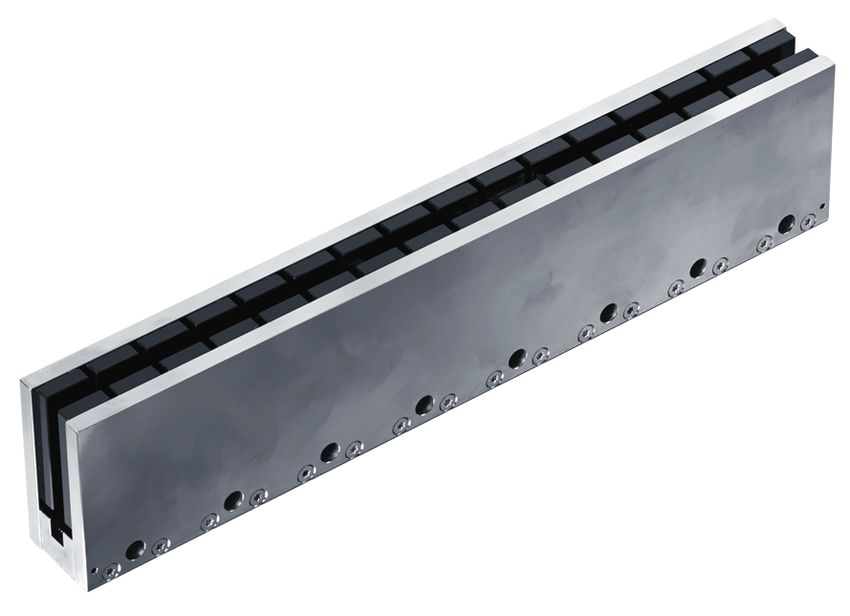
Table of content

Table of content
    Documented motors – AL38xx ................................................................................................................. 3

1 Foreword .................................................................................................................................................... 7
    1.1       Notes on the documentation.............................................................................................................. 7
    1.2       Documentation issue status .............................................................................................................. 8
    1.3       Intended use ...................................................................................................................................... 8

2 Guidelines and Standards ........................................................................................................................ 9
    2.1       EC declaration of conformity ............................................................................................................. 9

3 Safety ........................................................................................................................................................ 10
    3.1       Safety instructions ........................................................................................................................... 10
    3.2       Special safety instructions for the AL38xx ....................................................................................... 11

4 Handling ................................................................................................................................................... 13
    4.1       Transport ......................................................................................................................................... 13
    4.2       Storage ............................................................................................................................................ 13
    4.3       Maintenance / Cleaning ................................................................................................................... 13
    4.4       Disposal ........................................................................................................................................... 13

5 Product identification.............................................................................................................................. 14
    5.1       AL38xx scope of delivery................................................................................................................. 14
    5.2       AL38xx type key .............................................................................................................................. 14

6 Technical description.............................................................................................................................. 15
    6.1       Design of the motors ....................................................................................................................... 15
    6.2       General technical data..................................................................................................................... 15
              6.2.1         Power derating................................................................................................................. 16
    6.3       Standard features ............................................................................................................................ 17
              6.3.1         Coil unit, primary part (N/S) ............................................................................................. 17
              6.3.2         Magnet yoke, secondary part .......................................................................................... 17
    6.4       Additional equipment ....................................................................................................................... 18
              6.4.1         Screws and locating pins ................................................................................................. 18
              6.4.2         Servo drive and feedback system.................................................................................... 18

7 Mechanical installation ........................................................................................................................... 19
    7.1       Specification of the mounting surfaces ............................................................................................ 19
    7.2       Installation sequence ....................................................................................................................... 20
    7.3       Mounting the magnet yokes ............................................................................................................ 20
    7.4       Assembling the coil unit ................................................................................................................... 21
    7.5       Dismantling sequence ..................................................................................................................... 21

8 Electrical installation............................................................................................................................... 22
    8.1       Important notes................................................................................................................................ 22
    8.2       Connection of motors with flying wires ............................................................................................ 23
    8.3       Connection of motors with preassembled cables ............................................................................ 23
              8.3.1         AX5000 connection diagram for AL38xx and absolute value encoder ............................ 24
              8.3.2         AX5000 connection diagram for AL38xx and Sin/Cos encoder with zero pulse.............. 25
    8.4       Calculation of the brake resistor ...................................................................................................... 26
    8.5       Temperature sensor ........................................................................................................................ 26

4                                                                        Version: 3.6                                                                    AL3800
Table of content

             8.5.1         PTC specification............................................................................................................. 26
             8.5.2         NTC Specification ............................................................................................................ 27
    8.6      Polarity test ...................................................................................................................................... 27

9 Commissioning........................................................................................................................................ 28
    9.1      Important notes................................................................................................................................ 28
    9.2      General commissioning ................................................................................................................... 28
             9.2.1         Parameterization.............................................................................................................. 28
             9.2.2         Commissioning ................................................................................................................ 29
             9.2.3         Optimizing the control settings......................................................................................... 29
    9.3      Troubleshooting ............................................................................................................................... 30

10 Technical data.......................................................................................................................................... 31
    10.1 Term definitions ............................................................................................................................... 31
    10.2 AL38xx............................................................................................................................................. 32
             10.2.1        Technical drawing AL38xx............................................................................................... 33

11 Support and Service................................................................................................................................ 34

AL3800                                                                  Version: 3.6                                                                              5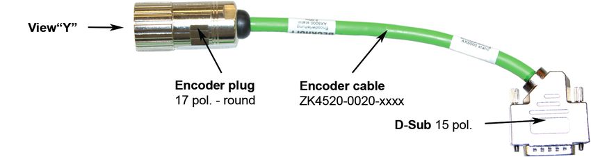
Table of content

6                  Version: 3.6   AL3800
Foreword

1                Foreword

1.1              Notes on the documentation
This description is only intended for the use of trained specialists in control and automation engineering who
are familiar with the applicable national standards.
It is essential that the documentation and the following notes and explanations are followed when installing
and commissioning the components.
It is the duty of the technical personnel to use the documentation published at the respective time of each
installation and commissioning.

The responsible staff must ensure that the application or use of the products described satisfy all the
requirements for safety, including all the relevant laws, regulations, guidelines and standards.

Disclaimer

The documentation has been prepared with care. The products described are, however, constantly under
development.
We reserve the right to revise and change the documentation at any time and without prior announcement.
No claims for the modification of products that have already been supplied may be made on the basis of the
data, diagrams and descriptions in this documentation.

Trademarks

Beckhoff®, TwinCAT®, EtherCAT®, EtherCAT P®, Safety over EtherCAT®, TwinSAFE®, XFC® and XTS® are
registered trademarks of and licensed by Beckhoff Automation GmbH.
Other designations used in this publication may be trademarks whose use by third parties for their own
purposes could violate the rights of the owners.

Patent Pending

The EtherCAT Technology is covered, including but not limited to the following patent applications and
patents:
EP1590927, EP1789857, DE102004044764, DE102007017835
with corresponding applications or registrations in various other countries.

The TwinCAT Technology is covered, including but not limited to the following patent applications and
patents:
EP0851348, US6167425 with corresponding applications or registrations in various other countries.

EtherCAT® is registered trademark and patented technology, licensed by Beckhoff Automation GmbH,
Germany

Copyright

© Beckhoff Automation GmbH & Co. KG, Germany.
The reproduction, distribution and utilization of this document as well as the communication of its contents to
others without express authorization are prohibited.
Offenders will be held liable for the payment of damages. All rights reserved in the event of the grant of a
patent, utility model or design.

AL3800                                           Version: 3.6                                                 7
Foreword

1.2             Documentation issue status
Origin of the document

This documentation was originally written in German. All other languages are derived from the German
original.

Product features

Only the product features specified in the current user documentation are valid. Further information given on
the product pages of the Beckhoff homepage, in emails or in other publications is not authoritative.

Issue              Comment
3.6                Chapter update:
                   Connection of motors with flying wires 8.2; NTC Specification 8.5.2
3.5                Chapter update:
                   Disposal 4.4
3.4                Chapter update:
                   EC declaration of conformity 2.1; Technical drawing AL38xx 10.2.1
3.3                Chapter update:
                   1.0 Foreword; 3.0 Safety
3.2                Chapter update:
                   8.2
3.1                Chapter update:
                   10.2
3.0                Complete revision
2.1                Version February 2005

1.3             Intended use
The ironless linear servomotors of the series AL38xx are cogging-free and therefore particularly suitable as
drives for axes with low mass or high demands on synchronism, e.g. in machines in the semiconductor
industry.

The thermal protection contact incorporated in the motor windings must be analyzed and monitored.

                                                 WARNING
                Caution - Risk of injury!
                Electronic equipment is not fail-safe. The machine manufacturer is responsible for ensuring
                that the connected motors and the machine are brought into a safe state in the event of a
                fault in the drive system.

The linear servomotors from the AL38xx series are exclusively installed as components into electrical
systems or machines and may only be put into operation as integrated components of the system or
machine.
The motors may only be operated under the ambient conditions defined in this documentation.

8                                               Version: 3.6                                            AL3800
Guidelines and Standards
2 Guidelines and Standards
CAUTION
Danger for persons, the environment or equipment
Linear servomotors from the AL38xx series are not products within the meaning of the EC machinery direc-
tive. Operation of the linear servomotors in machines or systems is only permitted once the machine or sys-
tem manufacturers has provided evidence of CE conformity of the complete machine or system.
2.1 EC declaration of conformity
Provision of EU Declaration of Conformity:
Beckhoff Automation GmbH & Co. KG will be glad to provide you with EU declarations of conformity
and manufacturer's declarations for all products upon request to info@beckhoff.com.
AL3800 Version: 3.6 9Safety
3 Safety
3.1 Safety instructions
Safety regulations
Please note the following safety instructions and explanations!
Product-specific safety instructions can be found on following pages or in the areas mounting, wiring,
commissioning etc.
Exclusion of liability
All the components are supplied in particular hardware and software configurations appropriate for the
application. Modifications to hardware or software configurations other than those described in the
documentation are not permitted, and nullify the liability of Beckhoff Automation GmbH & Co. KG.
Personnel qualification
This description is only intended for trained specialists in control, automation and drive engineering who are
familiar with the applicable national standards.
Description of symbols
In this documentation the following symbols are used with an accompanying safety instruction or note. The
safety instructions must be read carefully and followed without fail!
DANGER
Serious risk of injury!
Failure to follow the safety instructions associated with this symbol directly endangers the life and health of
persons.
WARNING
Risk of injury!
Failure to follow the safety instructions associated with this symbol endangers the life and health of per-
sons.
CAUTION
Personal injuries!
Failure to follow the safety instructions associated with this symbol can lead to injuries to persons.
NOTE
Damage to the environment or devices
Failure to follow the instructions associated with this symbol can lead to damage to the environment or
equipment.
Tip or pointer
This symbol indicates information that contributes to better understanding.
UL pointer
This symbol indicates important information about the UL-compliant.
10 Version: 3.6 AL3800Safety
3.2 Special safety instructions for the AL38xx
The safety instructions are designed to avert danger and must be followed during installation,
commissioning, production, troubleshooting, maintenance and trial or test assemblies.
The linear servomotors from the AL3xxx series are not capable of running independently and are always
installed into a machine or system. After installation the additional documentation and safety instructions
provided by the machine manufacturer must be read and followed.
WARNING
Serious risk of injury through high electrical voltage!
• Negligent, improper handling of the linear servomotor and bypassing of the safety de-
vices can lead to personal injury or death through electric shock.
• It must be ensured that the protective conductor has been firmly connected.
• The machine manufacturer must prepare a hazard analysis for the machine, and must
take appropriate measures to ensure that unexpected movements cannot lead to injury
to persons or to objects.
• Power leads may be live, even if the motor is not running. Never undo the electrical con-
nections to the motor when it is live. Under unfavorable conditions arcing may occur, re-
sulting in injury and damage to contacts.
• Disconnect the linear servomotor from the servo drive and secure it against reconnec-
tion before working on electrical parts with a voltage > 50 V.
• The DC link voltage of the servo drive may exceed 890 VDC. Wait until the DC link capac-
itors are discharged before touching live terminals. The voltage measured between the
DC+ and DC- terminals (X02) must have dropped to below 50 VDC.
WARNING
Serious risk of injury through hot surfaces!
• The surface temperature may exceed 50 °C, resulting in a risk of burns.
• Avoid touching the housing during or shortly after operation.
• Leave the linear servomotor to cool down for at least 15 minutes after it is switched off.
• Use a thermometer to check whether the surface has cooled down sufficiently.
NOTE
Danger to the environment or devices
• Carefully read this manual before using the linear servomotor thoroughly, paying particular attention to
the safety instructions. In the event of any uncertainties please notify your sales office immediately and
refrain from working on the linear servomotor.
• Only well trained, qualified electricians with sound knowledge of drive equipment may work on the de-
vice.
• Adhere without fail to the climatic conditions for the installation. Further information can be found in the
chapter Technical data and Mechanical installation.
• If a linear servomotor is installed in a machine it must not be commissioned until proof of compliance of
the machine with the latest version of the EC Machinery Directive has been provided. This includes all
relevant harmonized standards and regulations required for implementation of this Directive in national
legislation.
NOTE
Damage to the device due to inappropriate treatment
Treat the components of the linear servomotor with care, both in the packed and unpacked state. The mag-
net yokes are particularly sensitive. Never let the magnet yokes fall on the floor.
AL3800 Version: 3.6 11Safety
NOTE
Damage to the magnets at higher temperatures
The magnets should never be exposed to temperatures above 70° C. They can become demagnetized at
higher temperatures.
CAUTION
Magnetic attractive forces can lead to damage
• The magnetic plates exercise a powerful attractive force on any soft-magnetic materials such as iron.
These forces are more than the hand can manage. They can cause serious injuries.
• Do not bring any soft-magnetic objects closer than 10 cm to the magnetic side of the magnetic plates.
• During assembly, the magnet yokes may be subject to mutual attractive forces. The magnets of the
magnet yokes may be damaged by the end plate of an adjacent magnet yoke.
WARNING
Damage due to power failure
The linear servomotor is driven by a servo drive. It is possible for a power failure, or for some other serious
fault, to cause the motor to start up automatically. Provide mechanical safety equipment that will protect the
motor and your machine from being damaged in such circumstances.
12 Version: 3.6 AL3800Handling
4 Handling
4.1 Transport
Climate category: 2K3 according to EN 60721
Transport temperature: -25 °C - +70 °C, max. fluctuation 20 K/hour
Transport humidity: relative humidity 5% - 95%, non-condensing
The linear servomotor may only be transported by qualified personnel and in the manufacturer's original
packaging.
If the packaging is damaged, check the motor for visible damage. Inform the transport company and, if
necessary, the manufacturer.
4.2 Storage
Climate category: 2K3 according to EN 60721
Storage temperature: -25 °C - +70 °C, max. fluctuation 20 K/hour
Air humidity: relative humidity 5% - 95%, non-condensing
Storage time: without limitation
Store only in the manufacturer’s original packaging
4.3 Maintenance / Cleaning
• Maintenance and cleaning only by qualified personnel.
• Opening the motor invalidates the warranty.
• Clean the housing with isopropanol or similar.
NOTE
Destruction of the linear servomotor
Never immerse or spray the linear servomotor.
Proper functioning of the bearings and buffers, and guidance of the movable lines, must all be tested.
4.4 Disposal
In accordance with the WEEE 2012/19/EU Directives we take old devices and accessories back for
professional disposal, provided the transport costs are taken over by the sender.
Send the devices with the note “For disposal” to:
Beckhoff Automation GmbH & Co. KG
Huelshorstweg 20
D-33415 Verl
AL3800 Version: 3.6 13Product identification
5 Product identification
5.1 AL38xx scope of delivery
Please check that the delivery includes the following items:
• Motor from the AL3800 series
• Name plate
5.2 AL38xx type key
14 Version: 3.6 AL3800Technical description
6 Technical description
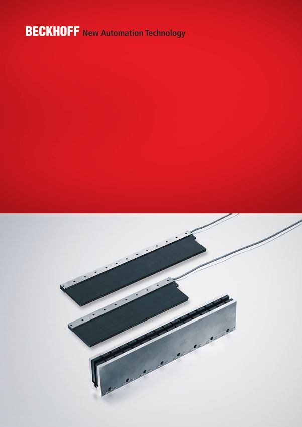
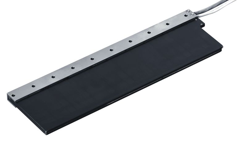
6.1 Design of the motors
The linear servomotors from the AL38xx series are ironless three-phase motors for high-quality servo
applications. In conjunction with our digital servo drive, they are particularly suitable for positioning tasks in
the semiconductor industry with demanding requirements in terms of synchronism and precision.
The motors from the AL38xx series are intended to be operated exclusively by the digital servo drive with
speed and torque control.
The linear servomotors have permanent magnets in the secondary section. This advanced neodymium
magnetic material makes a significant contribution to the motors' exceptional dynamic properties. A three-
phase coil unit supplied by the servo drive is housed in the coil unit. The motor has no brushes; the
commutation being implemented electronically in the servo drive.
Furthermore, a feedback system is necessary for operation. The suitable feedback system must be selected
on the basis of the application requirements. Dynamics, speed, contamination levels, resolution and the
servo drive employed must be considered
6.2 General technical data
Technical data AL38xx
Climate category 3K3 according to EN 60721
Ambient temperature (at rated values) +5 - +40 °C for installation altitudes up to 1000 m amsl
Permissible humidity (at rated values) 95% relative humidity, non-condensing
Installation altitude (currents and torques) For installation altitudes above 1000 m amsl and 40
°C
AL3800 Version: 3.6 15Technical description
6.2.1 Power derating
Ambient temperature
fT = Temperature utilisation factor
tA = Ambient temperature in °C
Calculation of the power data when exceeding the
specified temperature limit > 40 °C:
FCA_red = FCA x fT
Installation altitude
fH = Altitude utilisation factor
h = Altitude in metres
Calculation of the power data when exceeding the
specified installation altitude > 1000 m:
FCA_red = FCA x fH
Ambient temperature and installation altitude
Calculation of the power data when exceeding the specified limits:
Ambient temperature > 40 °C and installation altitude > 1000 m
FCA_red = FCA x fT x fH
16 Version: 3.6 AL3800Technical description 6.3 Standard features The ironless linear servomotors of the AL38xx series from Beckhoff are not self-contained systems. It includes various components such as a coil unit and magnet yokes and must be integrated into a complete machine concept or a complete working unit. The size and shape of the carrier frame, the design of the carriage, the type of rail and type of bearings, and the kind of buffer used depend on the application. The carrier frame and the carriage must be designed such that an air gap is created between the coil unit and the magnet yoke. 6.3.1 Coil unit, primary part (N/S) The N-type (normal winding) represents the preferred type. The S-type (speed winding) has a higher maximum speed and current consumption. The dimensions of the N- and S-types are identical. 6.3.2 Magnet yoke, secondary part The magnet yokes are available in different lengths. AL3800 Version: 3.6 17
Technical description

6.4              Additional equipment
You require further components for the proper installation of your linear servomotor.

These are not included in the scope of delivery.

6.4.1            Screws and locating pins

The screws and locating pins are needed to position and fasten the coil unit to the carriage, and also the
magnet yoke to the carrier frame.

Attribute                                                         AL38xx
Screws for magnet yokes (stainless)                               M6 x 50, EN ISO 4762
Screws for coil unit (steel);                                     M5, EN ISO 4762
Length depends on the thickness of the carriage
Locating pins (stainless)                                         3h8, EN ISO 8734

6.4.2            Servo drive and feedback system
The following components are required for the construction of a complete linear axis and its operation:
     • Servo drive, e.g.: AX5xxx from Beckhoff Automation GmbH & Co. KG.
     • Graduated rule and linear displacement transducer
     • Cables, plugs and guides
     • Mechanical support / machine bed

18                                                 Version: 3.6                                        AL3800
Mechanical installation
7 Mechanical installation
7.1 Specification of the mounting surfaces
The mounting surfaces for the magnet yokes and the coil unit must be extremely even, in order to prevent
bending forces.
• Evenness of the mounting surface for the coil unit: ≤ 0.1 mm
• Evenness of the mounting surface for the magnet yokes: ≤ 0.1 mm
The path of the magnet yokes (also referred to as magnetic track) and the coil unit must be aligned with each
other. In order to achieve contactless movement, the mounting surfaces of the coil unit and the magnetic
track must be parallel.
• Parallelism of the mounting surface of the coil unit relative to the magnetic track: ≤ 0.05 mm
AL3800 Version: 3.6 19Mechanical installation
7.2 Installation sequence
WARNING
Damage due to uncontrolled magnetic attractive forces
The sequence specified in this introduction for the installation must be followed. Deviation from the se-
quence may result in dangerous situations and damage through magnetic forces.
Complete the installation of the machine bed, before installing the linear motor components. Mount and align
the rails and the graduated rule on the machine bed. Fit the bearings, buffers and required cables on the
carriage. Make sure the carriage moves properly.
Installation order:
1. Mount the magnet yokes on the support frame of the machine.
2. Mount the coil unit on the carriage.
3. Connect the cables to the coil unit.
7.3 Mounting the magnet yokes
NOTE
Damage due to contamination
The mounting surface must always be free from contamination. Particles with a size of more than 0.1 mm
can result in incorrect configuration and damage to your linear motor.
Start the assembly with yoke 1. Align yoke with 3 mm alignment pins or a milling reference. Mount the
magnet yokes on the support frames. Observe the maximum tightening torque
An axis reference for the magnetic yokes is achieved as follows:
• Alignment pins in the center yoke (for short distances)
• Alignment pins along the entire path (for longer distances)
• Milling reference along the entire path (inside radius < 0.2 mm) for longer distances
The other magnet yokes can then be mounted, whereby the mutual attractive force of the magnet yokes can
be controlled and utilized for the mechanical contact.
20 Version: 3.6 AL3800Mechanical installation
7.4 Assembling the coil unit
NOTE
Damage due to contamination
The mounting surface must always be free from contamination. Particles with a size of more than 0.1 mm
can result in incorrect configuration and damage to the linear motor.
Mounting of the coil unit on the clean mounting surface of the carriage is not hindered by attractive forces!
An axis reference for the coil unit (CR) is achieved as follows:
• Two alignment pins next to the first and last bolt of the coil unit
• Milling reference along the entire path (inside radius < 0.2 mm)
Procedure:
1. Insert the coil unit in the magnet yoke and position it on the mounting surface
2. Align the coil unit with the axis reference
3. Secure the coil unit with bolts
4. Observe the specified tightening torque!
The exact air gap dimensions (A1 and A2) can only be achieved, if the references and measurements
mentioned above are adhered to.
NOTE
Damage caused by vibration
For applications that are subject to vibrations, the bolts must be secured (e.g. with clamping rings or thread
locking compound)
Thermal protection
If the linear motor is operated continuously at its rated output, thermal compound should be used, in
order to optimize the thermal contact between the coil unit and the mounting surface.
7.5 Dismantling sequence
WARNING
Damage due to uncontrolled magnetic attractive forces
The specified installation sequence must be followed! Deviation from the sequence may result in dangerous
situations due to magnetic attractive forces.
The correct dismantling sequence is as follows:
1. Disconnect the cables from the coil unit.
2. Remove the coil unit from the carriage.
3. Remove the magnet yokes from the support frame of the machine.
AL3800 Version: 3.6 21Electrical installation
8 Electrical installation
8.1 Important notes
DANGER
Serious risk of injury through electric shock!
• Only staff qualified and trained in electrical engineering are allowed to wire up the motor.
• Check the assignment of the servo drive and servomotor. Compare the rated voltage and the rated cur-
rent of the devices.
• Always make sure that the motors are de-energized during assembly and wiring, i.e. no voltage may be
switched on for any piece of equipment which is to be connected. Ensure that the control cabinet re-
mains turned off (barrier, warning signs etc.). The individual voltages will only be turned on again during
commissioning.
• Never undo the electrical connections to the motor when it is live. Control and power leads may be live,
even if the motor is not running.
NOTE
Smooth operation
• Ensure that there the servo drive and the motor are earthed properly. See below for further information
regarding EMC shielding and earthing. Earth the mounting plate and motor housing. Information about
the connection method can be found in the chapter entitled Connection of motors with preassembled ca-
bles
• Use only cables approved by Beckhoff for the operation of the AL38xx.
• Route the power and encoder cables as separately as possible from one another (separation > 20 cm).
This will improve the immunity of the system to electromagnetic interference.
• Lay all cables with an adequate cross-sectional area according to EN 60204. The recommended cross-
section can be found in the technical data.
• Wiring:
ð Connect the feedback cable
ð Connect the motor cables
ð Shielding at both ends (shield terminal or EMC plug)
NOTE
HF interference
• The ground symbol , which you will find in the wiring diagrams, indicates that you must provide
an electrical connection, with as large a surface area as possible, between the unit indicated and the
mounting plate in the control cabinet. This connection is to suppress HF interference and must not be
confused with the PE (protective earth) symbol (protective measure according to EN 60204).
22 Version: 3.6 AL3800Electrical installation
8.2 Connection of motors with flying wires
If motors with flying wires are ordered, a plug can be assembled as required. The assignment of the signals
to the wires is given in the tables below.
Performance
Wire Signal
Black U
Red V
White W
Green PE
Braid shield
Temperature contact
Wire Signal
White PTC
Green NTC
Brown PTC
Yellow NTC
Braid shield
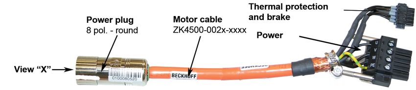
8.3 Connection of motors with preassembled cables
Beckhoff offers preassembled motor and feedback cables for safe, faster and flawless installation of the
motors. Beckhoff cables have been tested with regard to the materials, shielding and connectors used. They
ensure proper functioning and compliance with statutory regulations such as EMC, UL etc. The use of other
cables may lead to unexpected interference and invalidate the warranty.
• Carry out the wiring in accordance with the valid standards and regulations.
• Only use our preassembled shielded cables for the power and feedback connections. Incorrectly
installed shielding inevitably leads to EMC interference.
• Cables that move during the operation of the linear servomotor are always to be regarded as wearing
parts. It is advisable to install these with the help of a plug connector between the moved cable and the
motor cable of the coil unit such that simple replacement is ensured. The minimum bending radius of
the respective cable is to be taken from the corresponding data sheets.
• Detailed specifications of the cables can be found on our homepage under
Download→ Documentation→ Drive Technology→ Cables.
AL3800 Version: 3.6 23Electrical installation
8.3.1 AX5000 connection diagram for AL38xx and absolute value
encoder
* If no ConnectorBox is used, the ZK4540-0020-xxxx thermal protection contact cable is additionally
required. This is to be connected to X14 / 24.
24 Version: 3.6 AL3800Electrical installation
8.3.2 AX5000 connection diagram for AL38xx and Sin/Cos
encoder with zero pulse
* If no ConnectorBox is used, the ZK4540-0020-xxxx thermal protection contact cable is additionally
required. This is to be connected to X14 / 24.
AL3800 Version: 3.6 25Electrical installation 8.4 Calculation of the brake resistor During the braking procedure of the linear axis, energy is fed back into the servo drive. During the design the regenerative power must be calculated in order to select a brake resistor if necessary. To do this the peak and continuous power must be calculated. Pmax = 0.9 * (m * V²) / (2 tb) Prated = Pmax * tb / tz Pmax = maximum power of the brake resistor in Watts (W) Prated = continuous power of the brake resistor in Watts (W) M = moved mass (carriage + load) in kg V = carriage velocity in m/s tb = braking time in seconds tz = cycle time in seconds 8.5 Temperature sensor The coil unit is equipped with two temperature sensors, a PTC-1k and a NTC. The temperature sensors are used to monitor the temperature in the coil unit. The temperature cable contains four wires. 8.5.1 PTC specification The PTC-1k sensor exhibits a sharp rise in temperature when the temperature is close to a certain critical value, and therefore operates as a digital indicator. A gradual temperature signal can, however, not be generated from this PTC. At room temperature, the PTC has an electrical resistance of around 65 ohms. As the temperature rises up to a critical temperature, the resistance exhibits an almost linear rise up to 1000 ohms. Above this temperature, the resistance rises exponentially. The switching resistance is therefore 1000 ohms. The servo drive will immediately disconnect the power supply if this resistance is exceeded. This makes it possible to guard against overheating the motor. The thermal protection contact cable must therefore be properly connected to the servo drive. Temperature Resistance Up to 20° C below the critical temperature < 250 Ω Up to 5° C below the critical temperature < 550 Ω Switching resistance > 1000 Ω Above the critical temperature > 1330 Ω 26 Version: 3.6 AL3800
Electrical installation

8.5.2            NTC Specification
The NTC sensor is used for temperature monitoring in the coil unit.

Specifications of the NTC sensor
Tolerance ΔRR / ΔRR                                       5%
Max. Power                                                60 mW

T (ºC)       0    10    20      30     40     50        60         70    80    90    100    110      120     130
RNTC (Ω)   32650 19900 12490   8057   5327   3603      2488    1752     1258   918   680    511      389     301

8.6              Polarity test
                                                      NOTE
Protection of the linear servomotor
Before the test, make sure that the linear motor system has suitable electrical and mechanical protection.

Ensure that the count direction of the feedback matches the traversing direction of the motor. If this is the
case, the motor is connected correctly. If this is not the case, two phases (phases 1 and 3) of the motor
cable can be swapped, in order to correct the traversing direction.

All linear servomotors from Beckhoff are wired and connected in exactly the same way, so that a single test
is sufficient in order to determine the polarity of a motor/graduated rule combination. If more than one axis is
being constructed in a similar way, the polarity will be identical.

AL3800                                              Version: 3.6                                                27
Commissioning
9 Commissioning
9.1 Important notes
CAUTION
Serious risk of injury!
• Only specialist personnel with extensive knowledge in the areas of electrical engineering / drive technol-
ogy are allowed to install and commission the equipment.
• Check that all live connection points are protected against accidental contact.
• Never undo the electrical connections to the motor when it is live.
• The surface temperature of the motor can exceed 70 °C in operation. Check (measure) the temperature
of the motor. Wait until the motor has cooled down below 40 °C before touching it.
• Make sure that, even if the drive starts to move unintentionally, no danger can result for personnel or
machinery.
9.2 General commissioning
The procedure for commissioning is described as an example. A different method may be appropriate or
necessary, depending on the application of the equipment.
Once you have made sure that that the linear servomotor system of your application is properly mounted,
both mechanically and electrically, you can put your linear servomotor system into operation.
9.2.1 Parameterization
Depending on the components used (motor type, feedback system, servo drive) the following specific
parameters must be configured:
• the presence and switching mode of the limit switches (normally open / normally closed),
• the presence of an electromechanical brake,
• the type and interface,
• the motor type,
• the maximum continuous current,
• the maximum peak current,
• the switching resistance of the temperature sensor,
• safety settings,
• parameterization of the error reactions: tripping of the limit switches, switching off, overcurrent,
overspeed and emergency stop,
• commutation detection,
• parameters for the current controller (current loop),
• parameters for the speed controller (speed loop),
• parameters for the position controller (position loop),
28 Version: 3.6 AL3800Commissioning
9.2.2 Commissioning
• Check that the drive elements (carriage, magnetic plate, coil unit) are tightly fastened and correctly
adjusted.
• Can the carriage move unhindered over the entire motor track without touching the magnet yoke?
• Are the mechanical end-stops, limit switches and buffers properly dimensioned, and are they
configured correctly?
• Is the thermal protection contact cable connected?
• Does the combination of the motor and the graduated rule have the correct polarity?
• Check the wiring and connections to the motor and the servo drive. Check that the earthing is correct.
• Test the function of the holding brake, if used.
• Check whether the carriage of the motor can be moved freely (vent the brake beforehand if there is
one). Listen out for grinding noises.
• Check that all the required measures against accidental contact with live and moving parts have been
carried out.
• Carry out any further tests which are specifically required for your system.
• Now commission the drive according to the commissioning instructions for the servo drive.
• In multi-axis systems, individually commission each drive unit (servo drive/motor(s)).
• Is the track free from foreign bodies?
• Are cables correctly guided?
9.2.3 Optimizing the control settings
Generally speaking, settings made to the current controller do not affect the motor performance. A wide
range is also available for adequate possible settings. The settings of the current control depend only on the
application parameters of the servo drive and of the motor.
Due to its sensitivity to oscillations, to noise and to delays, the speed control only has limited use as a factor
for servo drive power. Please take the time to adjust this controller correctly before the position controller is
optimized. In this respect, be sure to also read the instructions in the manuals for the servo drive employed.
Adjustment of the controller
The position controller can only be adjusted correctly if the speed controller has been adjusted cor-
rectly beforehand.
AL3800 Version: 3.6 29Commissioning
9.3 Troubleshooting
The following table is to be seen as a “First Aid” box. There can be a large number of different reasons for a
fault, depending on the particular conditions in your system. The fault causes described below are mostly
those which directly influence the motor. Peculiarities which show up in the control behavior can usually be
traced back to an error in the parameterization of the servo drives.
Information about this can be found in the documentation for the servo drives and the commissioning
software.
Error Possible cause Measures to remove the cause of the fault
Motor does not move • Servo drive not enabled • Apply ENABLE signal
• Break in setpoint lead
• Check setpoint lead
• Motor phases in wrong sequence
• Correct the phase sequence
• Brake not released
• Check brake control
• Drive is mechanically blocked
• Check mechanism
Motor runs away • Motor phases in wrong sequence • Correct the phase sequence
Motor oscillates • Break in the shielding of the feedback • Replace the feedback cable
cable
• Amplification to high • Use the motor default values
Error message: brake • Short-circuit in the supply voltage lead to • Eliminate short-circuit
the motor holding brake
• Voltage too low
• Increase the voltage
• Faulty motor holding brake
• Replace the motor brake
Error message: output stage • Motor cable has short circuit or earth • Replace motor cable
fault leakage
• Motor has short circuit or earth leakage • Replace motor
Error message: feedback • Connector is not properly plugged in • Check the plug connector
• Break in cable, cable crushed or similar
• Check cables
• Internal error
• Read out the error messages
Brake does not grip • Required holding torque too high • Check the design
• Brake faulty
• Replace the motor brake
For multi-axis systems there may be further hidden reasons for faults.
30 Version: 3.6 AL3800Technical data 10 Technical data 10.1 Term definitions Winding type The winding type describes the structure of the windings. Depending on the coil unit this can be the N-type or the S-type, which differ in their electrical values. The N-type (normal) represents the standard. The S-type (speed) is characterized by a higher max. speed and a higher current consumption. Peak force Fp (N) The peak force specifies the maximum force of the motor. It cannot be constantly generated. Peak current (IPa) The peak current is the maximum permissible current. Continuous force with air cooling (Fca) The air-cooled motor can apply the force continuously, without water cooling. The value is specified for a motor with an aluminum cooling surface (thermal resistance 0.05K/W) at 20 °C. Continuous power loss (Pca) The continuous power dissipation is the max. power dissipation of the motor. It can be used for the calculation of the cooling systems. Power constant (Kf) The power constant specifies how much force in Newtons the motor generates with 1A effective sine current. The following applies: F=I x Kf (up to I = 2 x I0) Pole spacing The pole spacing is the period in which the magnetic field (north/south) of the magnetic plate repeats itself. AL3800 Version: 3.6 31
Technical data

10.2                   AL38xx
Technical data                             AL3803          AL3806                AL3809           AL3812       AL3818
Winding type                                 N/S             N/S                     N/S           N/S           N/-
Velocity (max.)                           2.7 m/s (N)     2.7 m/s (N)          2.7 m/s (N)      2.7 m/s (N)   2.7 m/s (N)
                                          6.6 m/s (S)     6.6 m/s (S)          6.6 m/s (S)      6.6 m/s (S)
Motor configuration                                        3-phase synchronous linear motors (230 V AC)
Peak force 3 s (FP)                         700 N           1400 N               2100 N           2800 N        4200 N
Peak current (IPa)                        5.6 A (N),      11.3 A (N),          16.9 A (N),      22.6 A (N),    34 A (N)
                                          13.9 A (S)       28 A (S)             42 A (S)         56 A (S)
Continuous force with air cooling (Fca)     141 N           282 N                    423 N         564 N        846 N
Continuous current (Ica)                  1.14 A (N)      2.27 A (N),           3.4 A (N),       4.5 A (N),    6.8 A (N)
                                           2.8 A (S)       5.6 A (S)            8.4 A (S)        11.2 A (S)
Continuous power loss (Pca)                 82 W            165 W                    247 N        330 W         494 W
Power constant (Kf)                                                 124 N/A (N),                              124 N/A (N)
                                                                    50.3 N / A (S)
Motor constant (Km)                       323 N²/W         647 N²/W             970 N²/W        1293 N²/W     1940 N²/W
Pole spacing                                                                     57 mm
Winding resistance Ph-Ph (Rf)             31.6 Ω (N),     15.8 Ω (N),          10.6 Ω (N),       8 Ω (N),      5.2 Ω (N)
                                           5.2 Ω (S)      2.58 Ω (S)           1.72 Ω (S)        1.3 Ω (S)
Winding inductance Ph-Ph (Lf)             56 mH (N),      28 mH (N),           18 mH (N),       14 mH (N),    9.4 mH (N)
                                          9.2 mH (S       4.6 mH (S)            3 mH (S)        2.4 mH (S)
Thermal resistance (Rth)                  1.04 °C/W       0.52 °C/W            0.35 °C/W        0.26 °C/W     0.17 °C/W
Magnetic attractive force (Fa)                                                        0N
Weight of the coil unit (Mp)               0.55 kg          0.95 kg              1.35 kg          1.75 kg       2.55 kg
Temperature sensor                                                              PTC 1 kΩ
Suitable servo drive                      AX5x03 (N)      AX5x06 (N),         AX5112 (N),       AX5112 (N),   AX5118 (N)
                                          AX5x06 (S)      AX5112 (S)          AX5125 (S)        AX5125 (S)
cable length not assembled                                                           1m
Minimum static bending radius                                              4 x cable diameter
Power cable outside diameter                                                    6.40 mm
Power cable configuration                                                     4 x 0.82 mm²
Sensor cable outside diameter                                                    4.3 mm
Sensor cable configuration                                                    4 x 0.14 mm²

32                                                      Version: 3.6                                               AL3800
Technical data 10.2.1 Technical drawing AL38xx AL3800 Version: 3.6 33
Support and Service

11                Support and Service
Beckhoff and their partners around the world offer comprehensive support and service, making available fast
and competent assistance with all questions related to Beckhoff products and system solutions.

Beckhoff's branch offices and representatives

Please contact your Beckhoff branch office or representative for local support and service on Beckhoff
products!

The addresses of Beckhoff's branch offices and representatives round the world can be found on her internet
pages:
http://www.beckhoff.com

You will also find further documentation for Beckhoff components there.

Beckhoff Headquarters

Beckhoff Automation GmbH & Co. KG

Huelshorstweg 20
33415 Verl
Germany

Phone:                                                 +49(0)5246/963-0
Fax:                                                   +49(0)5246/963-198
e-mail:                                                info@beckhoff.com

Beckhoff Support

Support offers you comprehensive technical assistance, helping you not only with the application of
individual Beckhoff products, but also with other, wide-ranging services:
     • support
     • design, programming and commissioning of complex automation systems
     • and extensive training program for Beckhoff system components

Hotline:                                               +49(0)5246/963-157
Fax:                                                   +49(0)5246/963-9157
e-mail:                                                support@beckhoff.com

Beckhoff Service

The Beckhoff Service Center supports you in all matters of after-sales service:
     • on-site service
     • repair service
     • spare parts service
     • hotline service

Hotline:                                               +49(0)5246/963-460
Fax:                                                   +49(0)5246/963-479
e-mail:                                                service@beckhoff.com

34                                               Version: 3.6                                         AL3800
More Information: www.beckhoff.com Beckhoff Automation GmbH & Co. KG Hülshorstweg 20 33415 Verl Germany Phone: +49 5246 9630 info@beckhoff.com www.beckhoff.com
You can also read