Manual Model 1355 5x High Current Output CANopen Soft Starter Module - Curtis Instruments
←
→
Page content transcription
If your browser does not render page correctly, please read the page content below
Manual
Model 1355
5x High Current Output
CANopen Soft Starter Module

                                                                                                         Curtis Instruments, Inc.
                                                                                                                200 Kisco Avenue
                                                                                                             Mt. Kisco, NY 10549
                                                                                                       www.curtisinstruments.com

      Read Instructions Carefully!

Specifications are subject to change without notice.
© 2020 Curtis Instruments, Inc. ® Curtis is a registered trademark of Curtis Instruments, Inc.
© The design and appearance of the products depicted herein are the copyright of Curtis Instruments, Inc.   53220, RevB September 2020
TABLE OF CONTENTS

         CHAPTERS
         1: OVERVIEW....................................................................................................................................... 1
              SOFT START MODE........................................................................................................................ 2
              PWM MODE................................................................................................................................... 2
              PARALLEL MODE (M4/M5) AND H-BRIDGE MODE (M1/M2)............................................................. 2
         2: INSTALLATION AND WIRING............................................................................................................. 3
              MOUNTING THE MODULE............................................................................................................... 3
              HIGH POWER CONNECTIONS.......................................................................................................... 5
              LOW POWER CONNECTIONS.......................................................................................................... 5
                    MAIN CONTACTOR DRIVER (PIN 2)........................................................................................... 6
                    CAN L/H (PINS 3, 4)................................................................................................................. 6
                    +15V AND GND (PINS 5, 12).................................................................................................... 7
                    SERIAL RX/TX (PINS 7, 8)......................................................................................................... 7
                    KSI (PIN 9)............................................................................................................................... 7
              WIRING: BASIC CONFIGURATION................................................................................................... 8
                    1355-X001 ACTUATOR OUTPUTS (PINS 1, 6, 10, 11, 13, 14).................................................... 8
                    1355-X101 DIGITAL INPUTS (PINS 1, 6, 10, 11, 13, 14)............................................................ 9
         3: PROGRAMMER MENUS................................................................................................................... 10
                    PROGRAM MENUS.................................................................................................................. 10
              MONITOR MENUS......................................................................................................................... 17

pg. ii                                                              Curtis 1355 CANopen Soft Starter Module Manual – September 2020
TABLE OF CONTENTS cont’d

             4: CANOPEN COMMUNICATIONS......................................................................................................... 20
                  BAUD RATES................................................................................................................................. 20
                  NODE ADDRESSES........................................................................................................................ 20
                  HEARTBEAT.................................................................................................................................. 20
                  EMERGENCY MESSAGES.............................................................................................................. 20
                        DATA BYTES 1 AND 2 – ERROR CATEGORY............................................................................. 21
                        DATA BYTE 3 – ERROR REGISTER........................................................................................... 21
                  PDOS............................................................................................................................................ 21
                  SDOS........................................................................................................................................... 23
                  COMMUNICATION PROFILE OBJECTS............................................................................................ 23
                  PARAMETER PROFILE OBJECTS.................................................................................................... 24
             5: DIAGNOSTICS AND TROUBLESHOOTING.......................................................................................... 33
             APPENDIX A........................................................................................................................................ 37
                  ELECTROMAGNETIC COMPATIBILITY (EMC)................................................................................... 37
                  ELECTROSTATIC DISCHARGE (ESD)............................................................................................... 38
             APPENDIX B....................................................................................................................................... 39
                        PC PROGRAMMING STATION (1314)........................................................................................ 39
                        HANDHELD PROGRAMMER (1313).......................................................................................... 39
                        PROGRAMMER FUNCTIONS.................................................................................................... 39
             APPENDIX C....................................................................................................................................... 40
                        SPECIFICATIONS..................................................................................................................... 40

Curtis 1355 CANopen Soft Starter Module Manual – September 2020                                                                                                         pg. iii
TABLE OF CONTENTS cont’d
FIGURES
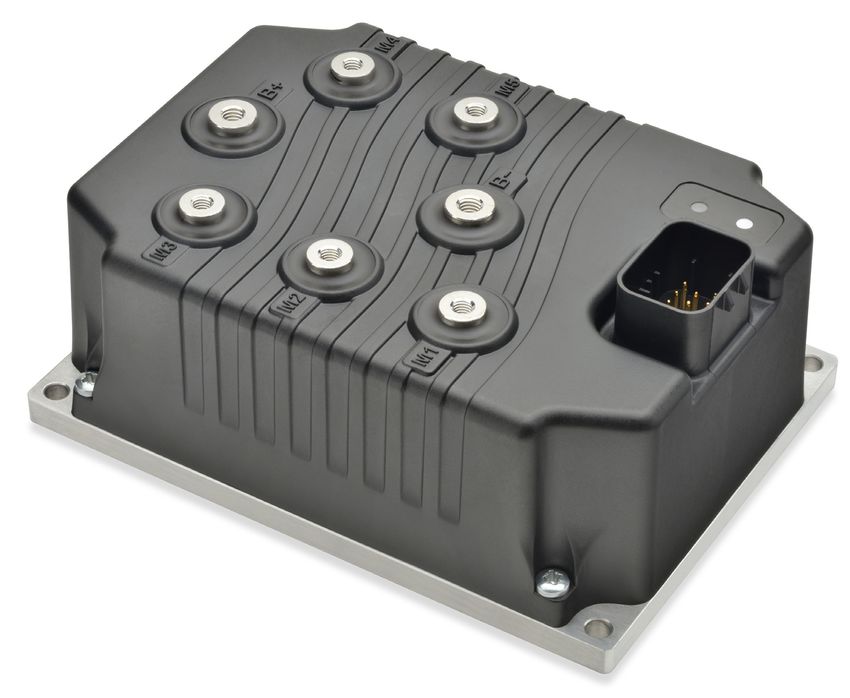
FIGURE 1: CURTIS 1355 CANOPEN ANCILLARY SOFT STARTER MODULE.............................................. 1
FIGURE 2: MOUNTING DIMENSIONS, CURTIS 1355 SOFT STARTER MODULE........................................ 3
FIGURE 3A: BASIC WIRING DIAGRAM, CURTIS 1355-X001 MODULE...................................................... 8
FIGURE 3B: BASIC WIRING DIAGRAM, CURTIS 1355-X101 MODULE...................................................... 9
FIGURE 4: DRIVER ACCELERATION...................................................................................................... 14
TABLES
TABLE 1: CONNECTOR PINOUT............................................................................................................ 6
TABLE 2: PROGRAM MENUS: 1311/1313 /1314 PROGRAMMER.......................................................... 10
TABLE 3: MONITOR MENUS: 1311/1313 /1314 PROGRAMMER........................................................... 17
TABLE 4: COMMUNICATION PROFILE OBJECT DICTIONARY................................................................. 23
TABLE 5: PARAMETER PROFILE OBJECT DICTIONARY......................................................................... 24
TABLE 5A: PARAMETER PROFILE OBJECT DICTIONARY: 1355-X001 ONLY........................................... 30
TABLE 5B: PARAMETER PROFILE OBJECT DICTIONARY: 1355-X101 ONLY........................................... 31
TABLE 6: TROUBLESHOOTING CHART................................................................................................. 34
TABLE C-1: SPECIFICATIONS: 1355 MODULE...................................................................................... 40
pg. iv Curtis 1355 CANopen Soft Starter Module Manual – September 2020Return to TOC Curtis 1355 CANopen Soft Starter Module Manual – September 2020
1 — OVERVIEW
The Curtis Model 1355 is a 5x high-current half bridge output module for soft start of electrical
motors. The 1355 is available with either three full actuator outputs or six digital inputs.
The module is designed to give it the flexibility to be used in a variety of sweepers/scrubbers. Typically
M1–M3 are used to drive the brushed permanent magnet motors that power the scrubbing brush pads,
and M4–M5 are used to drive the series-wound DC vacuum motors used to recover the used cleaning
solution from the floor. Use the 1355 as an ancillary controller to the vehicle or system manager.
The housing is designed to meet the difficult environment seen in material handling and outdoor
equipment. This water-tight design can survive high shock, vibration, and dust.
Figure 1
Curtis 1355
CANopen soft
starter module.
Features include:
• Programmable DC nominal supply: 24V, 36V, or 48V
• Five high-current half bridge drivers for motor loads (M1–M5)
• 3A driver output for a main (line) contactor, with overload protection
• KSI input
• CAN bus port
• Threaded busbars for B+, B–, and the five motor loads
1 — OVERVIEW pg. 1Curtis 1355 CANopen Soft Starter Module Manual – September 2020 Return to TOC
• 14-pin AMPSEAL connector for low-power loads (actuator loads, CAN bus, KSI, I/O, etc.)
• Protection from short circuits, under/over voltage, and reverse polarity
• Capacitor bank pre-charge circuit prevents arcing
• Field upgradeable firmware
• IP65 sealing
• Externally viewable dual power/status LED clearly flash the fault code
• Serial communication port for Curtis 1311/1313/1314 programmers
• 1355-X001: three full bridge drivers for linear actuators, typically used to lift/lower the brush
deck and the squeegee and control the detergent delivery pump
• 1355-X101: six digital inputs; Digital Input 6 can be used as an interlock.
SOFT START MODE
Soft Start mode provides a linear acceleration ramp from 0V to full voltage (pure DC, no PWM),
and linear deceleration from full voltage to 0V. In this way, it can reduce the starting current of the
motor, and also can effectively mitigate the surging problem of the inertia system when stopping.
PWM MODE
If Soft Start mode is not desired, M1–M5 can drive motors at PWM% within the 1-hour rating.
PARALLEL MODE (M4/M5) AND H-BRIDGE MODE (M1/M2)
The M4 and M5 outputs can be used in parallel to drive a single large motor load for vacuum. The
1355 uses the parameters of M4 to control the motor.
The M1 and M2 outputs can provide bi-directional motor control by connecting one motor load in
an H-bridge configuration. The 1355 uses the parameters of M1 to control the motor.
Both Parallel mode and H-Bridge mode can run in either Soft Start mode or PWM mode.
Familiarity with your Curtis 1355 module will help you install and operate it properly. We encourage
you to read this manual carefully. If you have questions, please contact the Curtis office nearest you.
pg. 2 1 — OVERVIEWReturn to TOC Curtis 1355 CANopen Soft Starter Module Manual – September 2020
2 — INSTALLATION AND WIRING
MOUNTING THE MODULE
The outline and mounting hole dimensions for the 1355 module are shown in Figure 2. The module
should be securely mounted to the vehicle using four M5 screws.
Care should be taken to prevent contaminating the connector area before the mating14-pin
CAUTION connector is installed. Once the system is plugged together, the 1355 meets the IP65 requirements
for environmental protection against dust and water. Nevertheless, in order to prevent external
corrosion and leakage paths from developing, the mounting location should be carefully chosen to
keep the module as clean and dry as possible.
Figure 2
Mounting dimensions, M6 x 1.0, 10 min, 2 plcs
Curtis 1355 soft starter M5 x 0.8, 10 min, 5 plcs
module.
Ø 6.00, 4 plcs
M4
M5
B+
120
108
M3
M2
M1
153
165
72
8.0
Dimensions in millimeters
2 — INSTALLATION AND WIRING pg. 3Curtis 1355 CANopen Soft Starter Module Manual – September 2020 Return to TOC
If the outputs will be used at or near their maximum ratings, it is recommended that the module be
mounted to a good heatsinking surface, such as an aluminum plate.
You will need to take steps during the design and development of your end product to ensure that its
EMC performance complies with applicable regulations; suggestions are presented in Appendix A.
The 1355 contains ESD-sensitive components. Use appropriate precautions in connecting,
disconnecting, and handling the module. See installation suggestions in Appendix A for protecting
the module from ESD damage.
Working on electrical systems is potentially dangerous. You should protect yourself against
uncontrolled operation, high current arcs, and outgassing from lead acid batteries:
UNCONTROLLED OPERATION — Some conditions could cause the motor to run out of control.
Disconnect the motor or jack up the vehicle and get the drive wheels off the ground before
attempting any work on the motor control circuitry.
CAUTION HIGH CURRENT ARCS — Batteries can supply very high power, and arcing can occur if they are
short circuited. Always open the battery circuit before working on the motor control circuit.
Wear safety glasses, and use properly insulated tools to prevent shorts.
LEAD ACID BATTERIES — Charging or discharging generates hydrogen gas, which can build up
in and around the batteries. Follow the battery manufacturer’s safety recommendations. Wear
safety glasses.
pg. 4 2 — INSTALLATION AND WIRINGReturn to TOC Curtis 1355 CANopen Soft Starter Module Manual – September 2020
HIGH POWER CONNECTIONS
The B+ and B– connections are via female-threaded M6 busbars; the suggested torque in 5.5 N∙m.
The five motor outputs (M1, M2, M3, M4, M5) are connected via female-threaded M5 busbars; the
suggested tightening torque is 3.5 N∙m.
The B+ and B– cables should be run close to each other between the module and the battery. For best
noise immunity the cables should not run across the center section of the module.
M1 and M2 can be used together to provide bi-directional motor control by connecting one motor
load across these two outputs, making a full bridge configuration. The motor is controlled by the
M1 programable parameters.
M4 and M5 can be used together as parallel outputs to drive a single large motor load for vacuum operation.
M1–M5 are protected from both over and under temperature; warnings are issued when the
temperature reaches the cutback threshold and output is disabled when the temperature reaches the
cutoff threshold.
LOW POWER CONNECTIONS
All connections are made through the 14-pin AMPSEAL connector. The low power connector will
mate to a 14-pin AMPSEAL wire header.
1 5
6 9
10 14
The module’s plastic cover features a molded-in receptacle that mates with a standard 14-pin
AMPSEAL housing and includes keying features to prevent incorrect insertion.The connector will
provide a proper seal and latch for the off-the-shelf AMPSEAL wire header/plug. Note that the 1355’s
CAUTION pins are not sealed until the mating connector is fully engaged and locked.
The 14 individual pins are characterized in Table 1, for the three actuator model (1355-X001) and
the six digital input model 1355-X101).
2 — INSTALLATION AND WIRING pg. 5Curtis 1355 CANopen Soft Starter Module Manual – September 2020 Return to TOC
Table 1 Connector Pinout
Pin 1355-X001 1355-X101
1 Actuator 2B Digital Input 1
2 Main Contactor Driver Main Contactor Driver
3 CAN L CAN L
4 CAN H CAN H
5 +15V +15V
6 Actuator 2A Digital Input 2
7 Serial Rx Serial Rx
8 Serial Tx Serial Tx
9 KSI KSI
10 Actuator 3B Digital Input 3
11 Actuator 3A Digital Input 4
12 B– B–
13 Actuator 1B Digital Input 5
14 Actuator 1A Digital Input 6 (Interlock)
The pins shared by both models are described below. The remaining pins (1, 6, 10, 11, 13, 14) are
model-specific and are described below the individual wiring diagrams.
Main Contactor Driver (pin 2)
This is a low side driver to switch the main contactor coil. The output is switched On after KSI is
closed and all power on seft-tests have been completed. It will open in the event of some severe faults
in the 1355 module.
CAN L/H (pins 3, 4)
The 1355 is configured to function as a CAN ancillary only. A CAN manager can read all inputs
and outputs, monitor values and error codes, control all outputs, and set parameter values. There
is no end-of-line termination resistor built into the module; if the 1355 is placed at the end of the
communication lines, an external 120 Ω ½ W resistor must be added across the lines.
The 1355 will be controlled by two single 8 byte CAN PDOs and will return two single 8 byte
PDOs over the CANopen protocol. SDOs can be sent to program various settings and features
within the module.
The following CAN status messages are transmitted: actual current, overload warning, overload trip,
over current, motor open fault, motor short fault, etc.
The following CAN commands are received: On, Off, % PWM, current limit value, overload time
value, etc.
CAN wiring should be kept away from the high current cables and cross it at right angles when
necessary.
pg. 6 2 — INSTALLATION AND WIRINGReturn to TOC Curtis 1355 CANopen Soft Starter Module Manual – September 2020
+15V and GND (pins 5, 12)
The +15V power supply for the programmer provides short circuit protection; the maximum output
is 60 mA. The ground at pin 12 completes the programmer circuit.
Serial Rx/Tx (pins 7, 8)
These provide the serial receive and transmit data channels for the programmer.
KSI (pin 9)
The KSI input turns the 1355 on and off via the vehicle’s keyswitch. The internal DC/DC has 0.51 A
current limit protection, and a TVS clamps the KSI input in the event of over voltage.
2 — INSTALLATION AND WIRING pg. 7Curtis 1355 CANopen Soft Starter Module Manual – September 2020 Return to TOC
WIRING: BASIC CONFIGURATION
Basic wiring diagrams are shown in Figure 3a (for the actuator models) and in Figure 3b (for the
digital input models).
MAIN COIL MAIN
J2-2 CONTACTOR
MAIN DRIVER
KEY SWITCH B+
J2-9
FROM MAIN KSI
CONTROL BOARD RIGHT BRUSH
J2-14
M6+ M1 M
SQEEGEE
ACTUATOR
M
J2-13 POWER
M6- LEFT BRUSH
FUSE
J2-6
M7+ M2 M
DECK
ACTUATOR M
J2-1
M7-
SIDE SWEEP
J2-11
M8+ M3 M
DETERGENT
PUMP M
J2-10
M8-
VACUUM 1
J2-4 CAN H M4 M
CAN PORT J2-3 CAN L
4 J2-5 VACUUM 2
+15V
SERIAL PORT
3 J2-8
Tx M5 M BATTERY
(4-pin Molex) 1 J2-7
Rx
2 J2-12
GND
B-
1355-X001
Figure 3a
Basic wiring diagram, Curtis 1355-X001 module.
1355-X001 Actuator Outputs (pins 1, 6, 10, 11, 13, 14)
Three full bridge linear actuator drivers can be used to lift/lower the brush deck and the squeegee,
and control the detergent delivery pump with control logic from the CAN manager.
100% PWM (pure DC) is not required; 0–95% PWM modulation is acceptable.
Stall Current Limit is programmable from 2.0 to 10.0 A. The actuator will be stopped if a large
increase of output current is detected. It is not possible to operate the motor in the stalled direction
until the actuator is first operated in the opposite direction.
The Stall Current Debounce Time is programmable from 0.0 to 5.0 seconds. This allows for high
start-up currents and momentary overloads.
Accel/Decel is programmable from 0.1 to 2.0 seconds.
pg. 8 2 — INSTALLATION AND WIRINGReturn to TOC Curtis 1355 CANopen Soft Starter Module Manual – September 2020
MAIN COIL MAIN
J2-2
MAIN DRIVER CONTACTOR
KEY SWITCH B+
J2-9
FROM MAIN KSI
CONTROL BOARD RIGHT BRUSH
J2-1
SWITCH 1
DIGITAL INPUT 1 M1 M
J2-6
DIGITAL INPUT 2
SWITCH 2 POWER
LEFT BRUSH
FUSE
J2-10
SWITCH 3
DIGITAL INPUT 3 M2 M
J2-11
DIGITAL INPUT 4
SWITCH 4
SIDE SWEEP
J2-13
DIGITAL INPUT 5
SWITCH 5 M3 M
J2-14
DIGITAL INPUT 6
SWITCH 6 (INTERLOCK)
VACUUM 1
J2-4 CAN H M4 M
CAN PORT J2-3 CAN L
4 J2-5 VACUUM 2
+15V
SERIAL PORT
3 J2-8
Tx M5 M BATTERY
(4-pin Molex) 1 J2-7
Rx
2 J2-12
GND
B-
1355-X101
Figure 3b
Basic wiring diagram, Curtis 1355-X101 module.
1355-X101 Digital Inputs (pins 1, 6, 10, 11, 13, 14)
The six digital inputs can be programmed as remote inputs from CAN or as command switches via
a programmer or over the CAN bus (SDO).
Input voltage range:
1355-4101 0–60 V
1355-5101 0–80 V.
Sink current:
1355-4101 3 mA at 60 V
1355-5101 3 mA at 80 V.
High level threshold: >10 V.
Pin 14 can be used as a digital input or as an interlock. When it is used as an interlock, this pin
provides a second enable input such as a seat switch, a pedal switch, or a charger inhibit.
2 — INSTALLATION AND WIRING pg. 9Curtis 1355 CANopen Soft Starter Module Manual – September 2020 Return to TOC
3 — PROGRAMMER MENUS
The Curtis handheld 1311/1313 programmer or 1314 PC programming station can be used to adjust
the programmable parameters, to read various monitored values, and to access fault information.
For information on the programmers, see Appendix B.
Program Menus
The programmable parameters are arranged in menus, as shown in Table 2.
Table 2 Program Menus: 1311/1313 /1314 Programmer
CONFIGURATION ........................... p. 11 ACTUATOR 1 – ACTUATOR 3 a....... p. 14 MISC b.......................................... p. 16
— Nominal Voltage — Enable a — Digital Input 1 Normally Closed b
— Overvoltage Warning Range — Stall Current Limit a — Digital Input 2 Normally Closed b
— Undervoltage Warning Range — Stall Current Debounce a — Digital Input 3 Normally Closed b
— Accel a — Digital Input 4 Normally Closed b
MAIN CONTACTOR ....................... p. 11
— Decel a — Digital Input 5 Normally Closed b
— Contactor Control
— Digital Input 6 Normally Closed b
— Pull In Voltage MODE......................................... p. 15
— Holding Voltage — Operation Mode b
— Main Contactor Current Limit — M1 PWM Mode
— M2 PWM Mode
INTERLOCKb ................................ p. 12
— M3 PWM Mode
— Interlock Typeb
— M4 PWM Mode
— Startup Lockout Typeb
— M5 PWM Mode
— Sequence Delay b
— M1 M2 H Bridge Mode
M1–M5........................................ p. 13 — M4 M5 Parallel Mode
— Enable — M1 M2 H Bridge Direction Input b
— Current Limit
CAN INTERFACE ........................ p. 16
— Regen Current Limit
— Node ID
— Motor Open Current
— Baud Rate
— Accel
— Heartbeat Rate
— Decel
— PDO Timeout
— PWM Demand
— Overload Time
— Controlled By b
— Inhibited By b
— Output Off Delay b
a
1355-X001 only
b
1355-X101 only
pg. 10 3 — PROGRAMMER MENUSReturn to TOC Curtis 1355 CANopen Soft Starter Module Manual – September 2020
CONFIGURATION MENU
PARAMETER ALLOWABLE RANGE DESCRIPTION
Nominal Voltage 36.0 – 48.0 V Sets the nominal voltage.
24.0 – 36.0 V for the 1355-4X01.
36.0 – 48.0 V for the 1355-5X01.
Overvoltage 2.0 – 14.0 V Sets the allowed voltage above the nominal voltage. When the capacitor
Warning Range bank voltage exceeds (Nominal Voltage + Overvoltage Warning Range), an
Overvoltage Warning message is issued on the CAN bus and programmer.
Undervoltage 2.0 – 14.0 V Sets the allowed voltage below the nominal voltage. When the capacitor bank
Warning Range voltage drops below (Nominal Voltage – Undervoltage Warning Range), an
Undervoltage Warning message is issued on the CAN bus and programmer.
MAIN CONTACTOR MENU
PARAMETER ALLOWABLE RANGE DESCRIPTION
Contactor Control On / Off When programmed On, the 1355 controls the main contactor.
When programmed Off, the main contactor is controlled by an external device.
Pull In Voltage 0 – 100 % This parameter allows a high initial voltage when the main contactor first
turns on, thus ensuring contactor closure. After 1 second, this peak voltage
drops to the contactor holding voltage.
Holding Voltage 0 – 100 % This parameter allows a reduced average voltage to be applied to the
contactor coil once it has closed. This parameter must be set high enough to
hold the contactor closed under all shock and vibration conditions the vehicle
will be subjected to.
Main Contactor 150 – 250 A This parameter limits the max current on the contactor. If the current is higher
Current Limit than the programmed limit, the 1355 will limit the current of all the outputs so
as to bring the main contactor current below its allowed limit. Meanwhile, the
1355 will report the fault on the CAN bus and programmer.
3 — PROGRAMMER MENUS pg. 11Curtis 1355 CANopen Soft Starter Module Manual – September 2020 Return to TOC
INTERLOCK MENU (1355-X101 only)
PARAMETER ALLOWABLE RANGE DESCRIPTION
Interlock Type 0–1 Selects the interlock type.
0 = Interlock turns on with Digital Input 6.
1 = Interlock turns on with KSI.
Startup Lockout Type 0–2 Selects the startup lockout type.
0 = No startup lockout.
1 = KSI-type startup lockout.
To start the motors, KSI must be turned on before a startup request
is received. Controller operation will be disabled immediately if the
startup request is active before KSI is enabled, and a sequence
fault will be declared. If the startup request is received before
interlock switch On but after KSI On, the motor will accelerate to the
requested speed as soon as interlock switch is closed.
2 = Interlock-type startup lockout.
To start the motors, the interlock must be turned on before receiving
a startup request. Controller operation will be disabled immediately if
the startup request is active before the interlock switch is closed, and
a sequence fault will be declared.
Normal operation is restored after a startup lockout by reapplying the startup
request in the correct sequence.
Sequence Delay 0.0 – 5.0 s Sets the PWM output shutoff delay after the interlock switch is turned off.
pg. 12 3 — PROGRAMMER MENUSReturn to TOC Curtis 1355 CANopen Soft Starter Module Manual – September 2020
M1 — M5 MENU*
PARAMETER ALLOWABLE RANGE DESCRIPTION
Enable On / Off This parameter enables/disables the driver output and fault check.
Note: Some severe faults, such as motor short and current sensor fault, will
still be checked even when this parameter is disabled.
Current Limit 10 – 100 A Sets the maximum current for the driver.
(24–36V models)
10 – 70 A
(36–48V models)
Regen Current Limit 10 – 100 A Sets the maximum current for the driver when operating in regen mode.
(24–36V models)
10 – 70 A
(36–48V models)
Motor Open Current 0.0 – 10.0 A Sets the minimum output current for this driver, below which a motor open
fault is declared when the motor is running.
Accel 0.1 – 2.0 s Sets the rate (in seconds) at which the driver output accelerates from zero to
100% PWM; see Figure 4.
Decel 0.1 – 2.0 s Sets the rate (in seconds) at which the driver output decelerates from 100%
PWM to zero.
PWM Demand 0 – 100 % Sets the requested PWM when operating in PWM mode.
Overload Time 1 – 20 s During current limiting, the Overload Trip timer Increases. If the timer exceeds
the Overload Time, output will be shut down.
Controlled By 0–6 This parameter defines which digital input will turn the driver.
(1355-X101 only) 0 = driver not controlled by any digital input.
1– 6 = driver controlled by digital input 1– 6.
Inhibited By 0–6 This parameter defines which digital input will inhibit the driver.
(1355-X101 only) 0 = driver not inhibited by any digital input.
1– 6 = driver inhibited by digital input 1– 6.
Output Off Delay 0.0 – 30.0 s The PWM will be shut off after the programmed Output Off Delay time expires
following a stop command.
* This menu is repeated for each of the five motor drivers.
3 — PROGRAMMER MENUS pg. 13Curtis 1355 CANopen Soft Starter Module Manual – September 2020 Return to TOC
ACTUATOR 1 — ACTUATOR 3 MENU (1355-X001 only)*
PARAMETER ALLOWABLE RANGE DESCRIPTION
Enable On / Off This parameter enables/disables the actuator output and fault check.
Note: Some severe faults, such as motor short and current sensor fault, will
still be checked even when this parameter is disabled.
Stall Current Limit 2 – 10 A Sets the maximum stall current for this actuator.
Stall Current Debounce 0.0 – 5.0 s This parameter allows a high startup current and momentary overload. If the
Stall timer exceeds the programmed debounce time, a stall fault is declared. It
is not possible to operate the motor in the stalled direction until the actuator is
first operated in the opposite direction.
Accel 0.1 – 2.0 s Sets the rate (in seconds) at which the actuator output accelerates from zero
to 100% PWM; see Figure 4.
Decel 0.1 – 2.0 s Sets the rate (in seconds) at which the actuator decelerates.
* This menu is repeated for each of the three actuators.
Figure 4
PWM DEMAND
Driver acceleration.
0% TIME
ACCEL
PWM accelerates from 0% to the programmed PWM Demand parameter at the
rate set by the Mx Accel or ActuatorX Accel parameters, and keeps that PWM
setting. The Accel parameters can be adjusted (over the CAN bus or with a Curtis
programer) from 0.1 to 2.0 seconds.
Note: In Soft Start mode the PWM Demand is not programmed and is always
100%.
pg. 14 3 — PROGRAMMER MENUSReturn to TOC Curtis 1355 CANopen Soft Starter Module Manual – September 2020
MODE MENU
PARAMETER ALLOWABLE RANGE DESCRIPTION
Operation Mode 0–1 Defines whether the 1355 will be independent of the CAN system or be a CAN
(1355-X101 only) ancillary.
0 = Independent mode.
1 = CAN Ancillary mode.
M1 PWM Mode On / Off Determines whether the motor will run in PWM mode or in Soft Start mode.
On = PWM mode.
Off = Soft Start mode.
M2 PWM Mode On / Off Determines whether the motor will run in PWM mode or in Soft Start mode.
On = PWM mode.
Off = Soft Start mode.
M3 PWM Mode On / Off Determines whether the motor will run in PWM mode or in Soft Start mode.
On = PWM mode.
Off = Soft Start mode.
M4 PWM Mode On / Off Determines whether the motor will run in PWM mode or in Soft Start mode.
On = PWM mode.
Off = Soft Start mode.
M5 PWM Mode On / Off Determines whether the motor will run in PWM mode or in Soft Start mode.
On = PWM mode.
Off = Soft Start mode.
M1 M2 H Bridge Mode On / Off Determines whether H Bridge mode is active.
On = H Bridge mode active.
Off = H Bridge mode inactive.
M4 M5 Parallel Mode On / Off Determines whether Parallel mode is active.
On = Parallel mode active.
Off = Parallel mode inactive.
M1 M2 H Bridge 1–6 Selects the digital input that will be the direction command for the M1 M2 H
Direction Input bridge.
(1355-X101 only) When the selected input is On, the motor will run forward.
When the selected input is Off, the motor will run in reverse.
This parameter is ignored when the 1355 is working in CAN Ancillary mode.
3 — PROGRAMMER MENUS pg. 15Curtis 1355 CANopen Soft Starter Module Manual – September 2020 Return to TOC
CAN INTERFACE MENU
PARAMETER ALLOWABLE RANGE DESCRIPTION
Node ID 1 – 127 Sets the Node ID of the 1355 CANopen ancillary system.
Must cycle KSI or send an NMT RESET 1355 or an NMT RESET CAN for the
new ID to take full effect.
Baud Rate 0–2 Sets the CAN bus baud rate.
0 = 125 kbps.
1 = 250 kbps.
2 = 500 kbps.
Must cycle KSI or send an NMT RESET 1355 or an NMT RESET CAN for the
new rate to take effect.
Heartbeat Rate 16 – 1000 ms Sets the rate at which heartbeat messages are sent from the 1355.
PDO Timeout 0 – 1000 ms Sets the PDO timeout period.
After the 1355 has sent a PDO TX, it will declare a PDO Timeout Fault if
the manager controller has not sent a reply PDO-RX message within the
programmed time. Either PDO1 RX or PDO2 RX will reset the timer.
Setting this PDO Timeout = 0 will disable this fault check.
MISC MENU (1355-X101 only)
PARAMETER ALLOWABLE RANGE DESCRIPTION
Digital Input 1 Normally Closed On / Off On = Normally closed.
Off = Normally open.
Digital Input 2 Normally Closed On / Off On = Normally closed.
Off = Normally open.
Digital Input 3 Normally Closed On / Off On = Normally closed.
Off = Normally open.
Digital Input 4 Normally Closed On / Off On = Normally closed.
Off = Normally open.
Digital Input 5 Normally Closed On / Off On = Normally closed.
Off = Normally open.
Digital Input 6 Normally Closed On / Off On = Normally closed.
Off = Normally open.
pg. 16 3 — PROGRAMMER MENUSReturn to TOC Curtis 1355 CANopen Soft Starter Module Manual – September 2020
MONITOR MENUS
Through its monitor menus, the Curtis programmer provides access to real-time data during vehicle
operation. This information is helpful during diagnostics and troubleshooting, and also while
adjusting programmable parameters.
The monitored variables are arranged in menus, as shown in Table 3.
Table 3 Monitor Menus: 1311/1313 /1314 Programmer
CURRENT..................................... p. 18 CONTROLLER............................... p. 19
— M1 Current — Internal Temperature
— M2 Current — Contactor State
— M3 Current — Interlock b
— M4 Current — Digital Input 1b
— M5 Current — Digital Input 2b
— Actuator 1 Current a — Digital Input 3b
— Actuator 2 Current a — Digital Input 4b
— Actuator 3 Current a — Digital Input 5b
— Digital Input 6b
VOLTAGE.................................... p. 18
— M1 Hourmeter
— KSI Voltage
— M2 Hourmeter
— Battery Voltage
— M3 Hourmeter
DUTY CYCLE................................. p. 18 — M4 Hourmeter
— M1 Duty Cycle — M5 Hourmeter
— M2 Duty Cycle — Actuator 1 Hourmeter a
— M3 Duty Cycle — Actuator 2 Hourmeter a
— M4 Duty Cycle — Actuator 2 Hourmeter a
— M5 Duty Cycle — CAN NMT State
— Actuator 1 Duty Cycle a
— Actuator 2 Duty Cycle a
— Actuator 3 Duty Cycle a
a
1355-X001 only
b
1355-X101 only
3 — PROGRAMMER MENUS pg. 17Curtis 1355 CANopen Soft Starter Module Manual – September 2020 Return to TOC
CURRENT MONITOR MENU
PARAMETER DISPLAY RANGE DESCRIPTION
M1 Current –150.0 – 150.0 A M1 motor current.
M2 Current –150.0 – 150.0 A M2 motor current.
M3 Current –150.0 – 150.0 A M3 motor current.
M4 Current –150.0 – 150.0 A M4 motor current.
M5 Current –150.0 – 150.0 A M5 motor current.
Actuator1 Current 0.0 – 15.0 A Actuator1 motor current.
(1355-X001 only)
Actuator2 Current 0.0 – 15.0 A Actuator2 motor current.
(1355-X001 only)
Actuator3 Current 0.0 – 15.0 A Actuator3 motor current.
(1355-X001 only)
VOLTAGE MONITOR MENU
PARAMETER DISPLAY RANGE DESCRIPTION
KSI Voltage 0.0 – 80.0 V Voltage at KSI input, pin 9.
Battery Voltage 0.0 – 80.0 V Voltage at the B+ busbar.
DUTY CYCLE MONITOR MENU
PARAMETER DISPLAY RANGE DESCRIPTION
M1 Duty Cycle 0 – 100 % M1 output duty cycle.
M2 Duty Cycle 0 – 100 % M2 output duty cycle.
M3 Duty Cycle 0 – 100 % M3 output duty cycle.
M4 Duty Cycle 0 – 100 % M4 output duty cycle.
M5 Duty Cycle 0 – 100 % M5 output duty cycle.
Actuator1 Duty Cycle –100 – 100 % Actuator1 output duty cycle.
(1355-X001 only)
Actuator2 Duty Cycle –100 – 100 % Actuator2 output duty cycle.
(1355-X001 only)
Actuator3 Duty Cycle –100 – 100 % Actuator3 output duty cycle.
(1355-X001 only)
pg. 18 3 — PROGRAMMER MENUSReturn to TOC Curtis 1355 CANopen Soft Starter Module Manual – September 2020
CONTROLLER MONITOR MENU
PARAMETER DISPLAY RANGE DESCRIPTION
Internal Temperature –40 – 125°C The internal temperature of the controller.
Contactor State On / Off Displays the state of the main contactor.
On = main contactor closed.
Off = main contactor open.
Interlock On / Off Displays the state of the interlock.
(1355-X101 only)
Digital Input 1 On / Off State of Digital Input 1.
(1355-X101 only)
...
Digital Input 6 On / Off State of Digital Input 6.
(1355-X101 only)
M1 Hourmeter 0 – 65535 hr
M2 Hourmeter 0 – 65535 hr
M3 Hourmeter 0 – 65535 hr
M4 Hourmeter 0 – 65535 hr Each hourmeter
accumulates
M5 Hourmeter 0 – 65535 hr “On” time
Actuator1 Hourmeter 0 – 65535 hr while its
(1355-X001 only) corresponding motor
is running.
Actuator2 Hourmeter 0 – 65535 hr
(1355-X001 only)
Actuator3 Hourmeter 0 – 65535 hr
(1355-X001 only)
CAN NMT State 0 – 127 Displays the NMT state of the 1355.
0 = Initialization.
4 = Stopped.
5 = Operational.
127 = Pre-operational.
3 — PROGRAMMER MENUS pg. 19Curtis 1355 CANopen Soft Starter Module Manual – September 2020 Return to TOC
4 — CANopen COMMUNICATIONS
The 1355 follows the industry trend (which Curtis proposed and supports) toward CANopen
communications. The 1355 runs the minimum state machine, which contains the standard mandatory
objects and follows the recommended SDO addressing scheme.
The 1355 processes two incoming PDOs (RX) and responds with two outgoing PDOs (TX). These
PDOs use a dynamic mapping method. All programmable parameters and monitor parameters are
accessible by standard SDO transfer.
The time between incoming PDOs is monitored and if excessive, a fault will be reported. This allows
the 1355 to know whether the system is under manager control. The 1355 also produces a cyclic
Heartbeat message, which is the CiA-preferred method for manager error control.
Emergency messages are sent sporadically whenever an error status flag within the 1355 changes
state. A minimum time between emergency messages prevents the bus from being flooded.
BAUD RATES
The 1355 runs at one of three selectable baud rates: 125 kbps, 250 kbps, or 500 kbps. The baud rate
can be changed by a Curtis programmer or by an SDO. Changes in the baud rate require an NMT
reset or key cycle.
NODE ADDRESSES
The node address is used to route messages to the 1355 and to denote messages from the 1355.
The node address is part of the COB ID and therefore also plays a part in message priority and bus
arbitration.
The 1355 can be assigned node address 1 through 127; node address 0 is reserved and unavailable.
Changes to the node address require an NMT reset or key cycle.
HEARTBEAT
The heartbeat message is a very low priority message, periodically sent by each ancillary device on
the bus. The heartbeat message has a single byte of data and requires no response. Once the 1355
completes its initialization, the first heartbeat will be issued and will continue until communication
is stopped.
The heartbeat message has only one data byte. The top bit is reserved and should be set to zero. The
bottom 7 bits hold the current NMT device state.
EMERGENCY MESSAGES
Emergency messages are high priority messages that announce the setting or clearing of a fault in a
ancillary device. These messages are originated by the ancillary, which sends 8 bytes of data.
Internal to the device, each fault is mapped to one of the device’s supported “Error Categories”
from an extensive list of possible Error Categories defined by CANopen. The fault reporting scheme
ensures that one Emergency message is sent in a CAN bus processing cycle during which one or
more faults within a given Error Category have been set or cleared. If a single fault has occurred since
the last processing cycle, then only one Emergency message is sent until such time as either a new
fault is detected or the previously reported fault has cleared. If multiple faults are detected in a given
cycle, the first fault is sent immediately, and the remaining faults are queued. Queued faults are sent
pg. 20 4 — CANopen COMMUNICATIONSReturn to TOC Curtis 1355 CANopen Soft Starter Module Manual – September 2020
on successive processing cycles until the queue is empty. The same scheme applies to the concurrent
clearing of faults and their corresponding Emergency messages.
The Emergency message will have device-specific fault bytes in addition to the CANopen mandatory
Error Register and Error Category. Note: Bit 0 of the Error Register object must always be set to 1
in any error situation.
Data Bytes 1 and 2 – Error Category
These data bytes, which are not explicitly defined by CANopen, are used to provide narrower
categorization up to and including individual faults when deemed appropriate. The error category
value implies the values that will appear in bytes 4 through 8 of the error message (the “Manufacture
Specific Error Field”). These additional bytes are used to provide supporting information about the
particular fault or faults being reported in an Error Category by a given Emergency message. The
following error categories are defined:
0x0000 Fault Reset or No Fault
0x1000 Generic Fault
0x1001 Generic Fault
Please refer to the product specific CANopen implementation manual for lists of errors occurring
under each of these categories
Data Byte 3 – Error Register
CANopen requires that the object ID of the error_register be included in each Emergency message.
Currently, only bit 0 of the Error Register is defined. This bit is set when any of the faults are set.
Data Bytes 4 through 8 – Manufacture Specific Error Field
The values that appear in these last 5 bytes depend on the Error Category that is being reported. The
last 5 bytes are defined as follows.
Error
Byte 4 Byte 5 Byte 6 Byte 7 Byte 8
Category
0x1000 Diagnostic1 Diagnostic2 Diagnostic3 Diagnostic4 Diagnostic5
0x1001 Diagnostic6 Diagnostic7 Diagnostic8 Diagnostic9 Diagnostic10
PDOs
The PDO (Process Data Object) communication packets conserve bus bandwidth by bundling the
values of a group of objects into a single message. The 1355 uses four PDOs, two from the system
manager and two responsive PDOs sent from the 1355 itself. The content of these PDOs can be
dynamic mapped as Curtis AC motor controllers. PDO messages have a medium priority and always
carry 8 bytes of data. The Curtis CANopen implementation requires that the incoming PDOs be
immediately responded to by an outgoing PDO. The 1355 will respond to the PDO-RX with its
PDO-TX within 16 ms.
4 — CANopen COMMUNICATIONS pg. 21Curtis 1355 CANopen Soft Starter Module Manual – September 2020 Return to TOC
The 1355 requires that the PDO-RX be cyclic from the manager. The cycle time must be less than
the programmed PDO Timeout. If the PDO-RX is not received within the programmed time,
the 1355 will flag a fault and enter the Pre-Operational State. If the PDO Timeout parameter is
set to 0, the timeout fault is disabled and the 1355 will respond to any PDO incoming at any rate
without faulting.
These charts show the PDOs exchanged by the 1355 with default mapping.
PDO1-RX (received from the system manager)
Byte 1 Byte 2 Byte 3 Byte 4 Byte 5 Byte 6 Byte 7 Byte 8
Actuator 1 Actuator 1 Actuator 2 Actuator 2 Actuator 3 Actuator 3 M1 PWM M1 PWM
PWM Low PWM High PWM Low PWM High PWM Low PWM High Demand Demand
Low High
PDO1-TX (sent in response to the system manager)
Byte 1 Byte 2 Byte 3 Byte 4 Byte 5 Byte 6 Byte 7 Byte 8
Actuator 1 Actuator 1 Actuator 2 Actuator 2 Actuator 3 Actuator 3 M1 PWM M1 PWM
Current Current Current Current Current Current Current Current
Low High Low High Low High/switch Low High
inputs status
PDO2-RX (received from the system manager)
Byte 1 Byte 2 Byte 3 Byte 4 Byte 5 Byte 6 Byte 7 Byte 8
M2 PWM M2 PWM M3 PWM M3 PWM M4 PWM M4 PWM M5 PWM M5 PWM
Demand Demand Demand Demand Demand Demand Demand Demand
Low High Low High Low High Low High
PDO2-TX (sent in response to the system manager)
Byte 1 Byte 2 Byte 3 Byte 4 Byte 5 Byte 6 Byte 7 Byte 8
M2 Current M2 Current M3 Current M3 Current M4 Current M4 Current M5 Current M5 Current
Low High Low High Low High Low High
Note: Actuator objects are only for the 1355-X001.
The switch inputs status object is only for the 1355-X101.
pg. 22 4 — CANopen COMMUNICATIONSReturn to TOC Curtis 1355 CANopen Soft Starter Module Manual – September 2020
SDOs
SDOs (Service Data Objects) are low priority packets that are designed for sporadic and occasional
use during normal runtime operation. There are two types of SDOs: expedited and block transfer.
The 1355 does not support large file uploads or downloads (using the block transfer), so all the SDOs
used by the 1355 are expedited SDOs.
The SDOs in the 1355 are used to set up and parameterize the module. They are also used to retrieve
basic module information (such as version or manufacture date) and monitor a few key internal
variables (mostly for system debug purposes). There are two types of SDO objects: Communication
Profile Objects and Parameter Profile Objects.
COMMUNICATION PROFILE OBJECTS
The communiction profile objects are shown below in Table 4.
Table 4 Communication Profile Object Dictionary
VALUE
NAME ACCESS INDEX SUB-INDEX DESCRIPTION
BYTES
Device Type RO 0x1000 0x00 0x00000000 Predefined type of CAN module.
4 bytes
Error Register RO 0x1001 0x00 0x00 or 0x01 = 0x01 if there is an error.
1 byte = 0x00 if there are no errors.
Node ID RW 0x100B 0x00 0x01 – 0x7F Node ID of this 1355 module.
1 byte
Emergency COB ID RO 0x1014 0x00 0x00000080 – 11-bit identifier of the emergency message.
0x000000FF Only the lowest 11 bits are valid. All other bits
4 bytes must be 0.
Heartbeat Rate RW 0x1017 0x00 16 ms – 1 s, Sets the cyclic repetition rate of the heartbeat
in 4 ms steps message.
2 bytes
Identity Object RO 0x1018 0x00 0x06 Length of this structure = 6 subindexes.
1 byte
0x01 0x00434900 Curtis ID as defined by CiA.
4 bytes
0x02 0x054B0FA1 Product code:
4 bytes 2 upper bytes = 1355.
2 lower bytes = model, X001 or X101.
0x03 0x01020304 Manager version in upper 2 bytes and
4 bytes Ancillary version in lower 2 bytes.
The bytes are split upper byte for HW and
lower byte for SW.
Example: Manager HW version 1 with SW
version 2, and Ancillary HW version 3 with
SW version 4 = 01020304.
For 1355-X101, the lower 2 bytes are 0.
0x04 0 – 999999 Serial number, up to 999,999.
4 bytes
0x05 1–99366 Date code up to 99, Dec 31.
4 bytes
0x06 A–Z ASCII code of manufacturer’s location.
0x41 – 0x5A
4 — CANopen COMMUNICATIONS pg. 23Curtis 1355 CANopen Soft Starter Module Manual – September 2020 Return to TOC
PARAMETER PROFILE OBJECTS
The parameter profile objects are shown in Table 5.
Table 5 Parameter Profile Object Dictionary
RANGE
NAME ACCESS INDEX SUB-INDEX RAW MAPPING Description
PDO1 RX Parameters RO 0x1400 0x00 1 No Number of PDO1 RX parameters.
0x01 n/a The first parameters of PDO1 RX.
PDO2 RX Parameters RO 0x1401 0x00 1 No Number of PDO2 RX parameters.
0x01 n/a The first parameters of PDO2 RX.
PDO1 RX Mapping RW 0x1600 0x00 n/a No Number of mapped application objects
in PDO1 RX.
PDO1 RX Mapping 1 0x01 PDO1 RX mapping for the 1st application
object to be mapped.
PDO1 RX Mapping 2 0x02 PDO1 RX mapping for the 2nd
application object to be mapped.
... ... PDO1 RX mapping for 3rd–7th objects.
PDO1 RX Mapping 8 0x08 PDO1 RX mapping for the 8th application
object to be mapped.
PDO2 RX Mapping RW 0x1601 0x00 n/a No Number of mapped application objects
in PDO2 RX.
PDO2 RX Mapping 1 0x01 PDO2 RX mapping for the 1st application
object to be mapped.
PDO2 RX Mapping 2 0x02 PDO2 RX mapping for the 2nd
application object to be mapped.
... ... PDO2 RX mapping for 3rd–7th objects.
PDO2 RX Mapping 8 0x08 PDO2 RX mapping for the 8th application
object to be mapped.
PDO1 TX Parameters RO 0x1800 0x00 1 No Number of PDO1 TX parameters.
0x01 n/a The first parameters of PDO1 TX.
PDO2 TX Parameters RO 0x1801 0x00 1 No Number of PDO2 TX parameters.
0x01 n/a The first parameters of PDO2 TX.
PDO1 TX Mapping RW 0x1A00 0x00 n/a No Number of mapped application objects
in PDO1 TX.
PDO1 TX Mapping 1 0x01 PDO1 TX mapping for the 1st application
object to be mapped.
PDO1 TX Mapping 2 0x02 PDO1 TX mapping for the 2nd
application object to be mapped.
... ... PDO1 TX mapping for 3rd–7th objects.
PDO1 TX Mapping 8 0x08 PDO1 TX mapping for the 8th application
object to be mapped.
pg. 24 4 — CANopen COMMUNICATIONSReturn to TOC Curtis 1355 CANopen Soft Starter Module Manual – September 2020
Table 5 Parameter Profile Object Dictionary, cont'd
RANGE
NAME ACCESS INDEX SUB-INDEX RAW MAPPING Description
PDO2 TX Mapping RW 0x1A01 0x00 n/a No Number of mapped application objects
in PDO2 TX.
PDO2 TX Mapping 1 0x01 PDO2 TX mapping for the 1st application
object to be mapped.
PDO2 TX Mapping 2 0x02 PDO2 TX mapping for the 2nd
application object to be mapped.
... ... PDO2 TX mapping for 3rd–7th objects.
PDO2 TX Mapping 8 0x08 PDO2 TX mapping for the 8th application
object to be mapped.
Nominal Voltage RW 0x3048 0x00 1536 – 2304, No 24–36V for 1355-4X01,
2304 – 3072 36–48V for 1355-5X01.
M1 Current Limit RW 0x3101 0x00 100 – 1000, No Defines the maximum current of M1:
or 100 – 700 10 –100A for 1355-4X01 and
10 –70A for 1355-5X01.
M2 Current Limit RW 0x3102 0x00 100 – 1000, No Defines the maximum current of M2:
or 100 – 700 ranges are as shown for M1.
M3 Current Limit RW 0x3103 0x00 100 – 1000, No Defines the maximum current of M3:
or 100 – 700 ranges are as shown for M1.
M4 Current Limit RW 0x3104 0x00 100 – 1000, No Defines the maximum current of M4:
or 100 – 700 ranges are as shown for M1.
M5 Current Limit RW 0x3105 0x00 100 – 1000, No Defines the maximum current of M5:
or 100 – 700 ranges are as shown for M1.
Motor Control RW 0x3106 0x00 0 – 255 Yes bit0 controls M1 1=Run 0=Stop.
bit1 controls M2 1=Run 0=Stop.
bit2 controls M3 1=Run 0=Stop.
bit3 controls M4 1=Run 0=Stop.
bit4 controls M5 1=Run 0=Stop.
bit5 controls H Bridge direction:
1=Fwd 0=Rev. Note: in H-Bridge
mode, the 1355 uses the parameters
of M1; M2’s parameters are ignored.
Motor Mode RW 0x3107 0x00 0 – 255 Yes bit0 M1 PWM mode 1=Active 0=Inactive.
bit1 M2 PWM mode 1=Active 0=Inactive.
bit2 M3 PWM mode 1=Active 0=Inactive.
bit3 M4 PWM mode 1=Active 0=Inactive.
bit4 M5 PWM mode 1=Active 0=Inactive.
M1 Overload Time RW 0x3108 0x00 1000 –20000 No Defines the max overload time:
1000 – 20000 ms.
M2 Overload Time RW 0x3109 0x00 1000 –20000 No The output is shut down once the timer
M3 Overload Time RW 0x310A 0x00 1000 –20000 No expires.
M4 Overload Time RW 0x310B 0x00 1000 –20000 No
M5 Overload Time RW 0x310C 0x00 1000 –20000 No
M1 Accel RW 0x310D 0x00 1– 20 No 0.1– 2.0 s
M2 Accel RW 0x310E 0x00 1– 20 No 0.1– 2.0 s
M3 Accel RW 0x310F 0x00 1– 20 No 0.1– 2.0 s
M4 Accel RW 0x3113 0x00 1– 20 No 0.1– 2.0 s
4 — CANopen COMMUNICATIONS pg. 25Curtis 1355 CANopen Soft Starter Module Manual – September 2020 Return to TOC
Table 5 Parameter Profile Object Dictionary, cont'd
RANGE
NAME ACCESS INDEX SUB-INDEX RAW MAPPING Description
M5 Accel RW 0x3114 0x00 1– 20 No 0.1– 2.0 s
M1 PWM Demand RW 0x3118 0x00 0 – 32767 Yes 0 –100 %
M2 PWM Demand RW 0x3119 0x00 0 – 32767 Yes 0 –100 %
M3 PWM Demand RW 0x311A 0x00 0 – 32767 Yes 0 –100 %
M4 PWM Demand RW 0x311B 0x00 0 – 32767 Yes 0 –100 %
M5 PWM Demand RW 0x311C 0x00 0 – 32767 Yes 0 –100 %
M1 M2 H Bridge Mode RW 0x311D 0x00 0–1 No 0 = H Bridge mode inactive; 1= H Bridge
mode active.
M4 M5 Parallel Mode RW 0x311E 0x00 0–1 No 0 = Parallel mode inactive; 1= Parallel
mode active. Note: In Parallel mode,
the 1355 uses M4’s parameters. M5’s
parameters are ignored except for the
current limit. The current limit range in
Parallel mode is 20–200A, which is the
total current limit of M4 and M5.
Motor Enable RW 0x311F 0x00 0 – 255 No bit0 M1 Enable.
bit1 M2 Enable.
bit2 M3 Enable.
bit3 M4 Enable.
bit4 M5 Enable.
bit5 Actuator1 Enable. a
bit6 Actuator2 Enable. a
bit7 Actuator3 Enable. a
When the output is disabled, the 1355
will not check the relative faults except
for some severe faults such as motor
short and current sensor fault.
M1 Duty Cycle RO 0x3120 0x00 0 – 32767 Yes 0 – 100%
M2 Duty Cycle RO 0x3121 0x00 0 – 32767 Yes 0 – 100%
M3 Duty Cycle RO 0x3122 0x00 0 – 32767 Yes 0 – 100%
M4 Duty Cycle RO 0x3123 0x00 0 – 32767 Yes 0 – 100%
M5 Duty Cycle RO 0x3124 0x00 0 – 32767 Yes 0 – 100%
M1 Armature Current RO 0x3126 0x00 –1500 – 1500 Yes –150.0 – 150.0 A
M2 Armature Current RO 0x3127 0x00 –1500 – 1500 Yes –150.0 – 150.0 A
M3 Armature Current RO 0x3128 0x00 –1500 – 1500 Yes –150.0 – 150.0 A
M4 Armature Current RO 0x3129 0x00 –1500 – 1500 Yes –150.0 – 150.0 A
M5 Armature Current RO 0x312A 0x00 –1500 – 1500 Yes –150.0 – 150.0 A
Baud Rate RW 0x3142 0x00 0–2 No 0 = 125 kbps.
1 = 250 kbps.
2 = 500 kbps.
The default setting is 1 (250 kbps).
PDO Timeout RW 0x3149 0x00 0 –1000 No Time interval within which the PDO-
RX must be received or a fault will be
flagged. The default setting is 100 ms.
a
1355-X001 only
pg. 26 4 — CANopen COMMUNICATIONSReturn to TOC Curtis 1355 CANopen Soft Starter Module Manual – September 2020
Table 5 Parameter Profile Object Dictionary, cont'd
RANGE
NAME ACCESS INDEX SUB-INDEX RAW MAPPING Description
Diagnostic1 RO 0x3256 0x00 0 – 255 Yes bit0 Precharge Fault.
bit1 Main Contactor Overload.
bit2 Main Weld Fault.
bit3 Main DNC Fault.
bit4 Overvoltage Warning.
bit5 Undervoltage Warning.
bit6 Overvoltage Cutoff.
bit7 Undervoltage Cutoff.
Diagnostic2 RO 0x3257 0x00 0 – 255 Yes bit0 M1 Open.
bit1 M2 Open.
bit2 M3 Open.
bit3 M4 Open.
bit4 M5 Open.
bit5 Actuator1 Open. a
bit6 Actuator2 Open. a
bit7 Actuator3 Open. a
Diagnostic3 RO 0x3258 0x00 0 – 255 Yes bit0 M1 Overload Warning.
bit1 M2 Overload Warning.
bit2 M3 Overload Warning.
bit3 M4 Overload Warning.
bit4 M5 Overload Warning.
bit5 Actuator1 Overload Warning. a
bit6 Actuator2 Overload Warning. a
bit7 Actuator3 Overload Warning. a
Diagnostic4 RO 0x3259 0x00 0 – 255 Yes bit0 M1 Over Current.
bit1 M2 Over Current.
bit2 M3 Over Current.
bit3 M4 Over Current.
bit4 M5 Over Current.
bit5 Actuator1 Over Current. a
bit6 Actuator2 Over Current. a
bit7 Actuator3 Over Current. a
Diagnostic5 RO 0x325A 0x00 0 – 255 Yes bit0 M1 Motor Short.
bit1 M2 Motor Short.
bit2 M3 Motor Short.
bit3 M4 Motor Short.
bit4 M5 Motor Short.
bit5 Actuator1 Motor Short. a
bit6 Actuator2 Motor Short. a
bit7 Actuator3 Motor Short. a
Diagnostic6 RO 0x325B 0x00 0 – 255 Yes bit0 M1 Current Sensor Fault.
bit1 M2 Current Sensor Fault.
bit2 M3 Current Sensor Fault.
bit3 M4 Current Sensor Fault.
bit4 M5 Current Sensor Fault.
bit5 Over Temperature Cutoff.
bit6 Under Temperature Cutoff.
bit7 [reserved].
a
1355-X001 only
4 — CANopen COMMUNICATIONS pg. 27Curtis 1355 CANopen Soft Starter Module Manual – September 2020 Return to TOC
Table 5 Parameter Profile Object Dictionary, cont'd
RANGE
NAME ACCESS INDEX SUB-INDEX RAW MAPPING Description
Diagnostic7 RO 0x325C 0x00 0 – 255 Yes bit0 M1 Overload Trip.
bit1 M2 Overload Trip.
bit2 M3 Overload Trip.
bit3 M4 Overload Trip.
bit4 M5 Overload Trip.
bit5 Actuator1 Stall Fault. a
bit6 Actuator2 Stall Fault. a
bit7 Actuator3 Stall Fault. a
Diagnostic8 RO 0x325D 0x00 0 – 255 Yes bit0 EEPROM Fault.
bit1 PDO Timeout Fault.
bit2 CAN Bus Fault.
bit3 Actuator Timeout. a
bit4 Sequence Fault. b
bit5 Over Temperature Cutback.
bit6 Under Temperature Cutback.
bit7 Main Missing Fault.
Fault History1 RO 0x325E 0x00 0 – 255 Yes bit0 Precharge Fault.
bit1 Main Contactor Overload.
bit2 Main Weld Fault.
bit3 Main DNC Fault.
bit4 [reserved].
bit5 [reserved].
bit6 Overvoltage Cutoff.
bit7 Undervoltage Cutoff.
Fault History2 RO 0x325F 0x00 0 – 255 Yes See Diagostic2.
Fault History3 RO 0x3260 0x00 0 – 255 Yes [reserved]
Fault History4 RO 0x3261 0x00 0 – 255 Yes See Diagostic4.
Fault History5 RO 0x3262 0x00 0 – 255 Yes See Diagostic5.
Fault History6 RO 0x3263 0x00 0 – 255 Yes See Diagostic6.
Fault History7 RO 0x3264 0x00 0 – 255 Yes See Diagostic7.
Fault History8 RO 0x3265 0x00 0 – 255 Yes See Diagostic8.
M1 Hourmeter RO 0x3266 0x00 0 – 65535 Yes 0 – 65535 hr
M2 Hourmeter RO 0x3267 0x00 0 – 65535 Yes 0 – 65535 hr
M3 Hourmeter RO 0x3268 0x00 0 – 65535 Yes 0 – 65535 hr
M4 Hourmeter RO 0x3269 0x00 0 – 65535 Yes 0 – 65535 hr
M5 Hourmeter RO 0x326A 0x00 0 – 65535 Yes 0 – 65535 hr
Internal Temperature RO 0x326E 0x00 –40 – 125 Yes –40 – 125 °C.
M1 Regen Current Limit RW 0x326F 0x00 100 – 1000 Yes 1355-4X01: 10.0 – 100.0 A
100 – 700 1355-5X01: 10.0 – 70.0 A
M2 Regen Current Limit RW 0x3270 0x00 100 – 1000 Yes 1355-4X01: 10.0 – 100.0 A
100 – 700 1355-5X01: 10.0 – 70.0 A
M3 Regen Current Limit RW 0x3271 0x00 100 – 1000 Yes 1355-4X01: 10.0 – 100.0 A
100 – 700 1355-5X01: 10.0 – 70.0 A
M4 Regen Current Limit RW 0x3272 0x00 100 – 1000 Yes 1355-4X01: 10.0 – 100.0 A
100 – 700 1355-5X01: 10.0 – 70.0 A
a
1355-X001 only
b
1355-X101 only
pg. 28 4 — CANopen COMMUNICATIONSYou can also read