Catalog 2020 2.0 μm Laser & Accessories - Futonics Laser GmbH
←
→
Page content transcription
If your browser does not render page correctly, please read the page content below
Catalog 2020 2.0 μm Laser & Accessories
CONTENT

ABOUT FUTONICS . . . . . . . . . . . . . . . . . . . . . . . . . . . . . . . . . . . . . . . . . . . . . . . . . . . . . . . . .                1
APPLICATIONS . . . . . . . . . . . . . . . . . . . . . . . . . . . . . . . . . . . . . . . . . . . . . . . . . . . . . . . . . . . .            2-3
        WELDING APPLICATIONS. . . . . . . . . . . . . . . . . . . . . . . . . . . . . . . . . . . . . . . . . . . . . . . .                     4-5
               Laser transmission welding. . . . . . . . . . . . . . . . . . . . . . . . . . . . . . . . . . . . . . . . .                      7-8
                Heat conduction welding . . . . . . . . . . . . . . . . . . . . . . . . . . . . . . . . . . . . . . . . . .                     9
                TWIST welding process . . . . . . . . . . . . . . . . . . . . . . . . . . . . . . . . . . . . . . . . . . . .                   9
        LASER CUTTING APPLICATIONS . . . . . . . . . . . . . . . . . . . . . . . . . . . . . . . . . . . . . . . . .                            10-13
        MARKING, ENGRAVING, LABELLING . . . . . . . . . . . . . . . . . . . . . . . . . . . . . . . . . . . . . . .                             14-15
                Marking & engraving of metals, polymers . . . . . . . . . . . . . . . . . . . . . . . . . . . . .  		 15

                Labeling von Lebensmitteln . . . . . . . . . . . . . . . . . . . . . . . . . . . . . . . . . . . . . . . .                      15
LASER SYSTEMS . . . . . . . . . . . . . . . . . . . . . . . . . . . . . . . . . . . . . . . . . . . . . . . . . . . . . . . . . . .             16-17
        IFL10 - IFL50. . . . . . . . . . . . . . . . . . . . . . . . . . . . . . . . . . . . . . . . . . . . . . . . . . . . . . . . . . . .    18-19
        IFL200 - IFL250. . . . . . . . . . . . . . . . . . . . . . . . . . . . . . . . . . . . . . . . . . . . . . . . . . . . . . . . .        20-21
        IFL10P - IFL30P . . . . . . . . . . . . . . . . . . . . . . . . . . . . . . . . . . . . . . . . . . . . . . . . . . . . . . . . .       22-23
OPTICAL SYSTEMS . . . . . . . . . . . . . . . . . . . . . . . . . . . . . . . . . . . . . . . . . . . . . . . . . . . . . . . . .               24-25
        COLLIMATORS . . . . . . . . . . . . . . . . . . . . . . . . . . . . . . . . . . . . . . . . . . . . . . . . . . . . . . . .             26-27
        F-THETA LENSES . . . . . . . . . . . . . . . . . . . . . . . . . . . . . . . . . . . . . . . . . . . . . . . . . . . . . . .            28-29
        PROCESSING HEADS . . . . . . . . . . . . . . . . . . . . . . . . . . . . . . . . . . . . . . . . . . . . . . . . . . .                  30-37
        INSTALLATIONS . . . . . . . . . . . . . . . . . . . . . . . . . . . . . . . . . . . . . . . . . . . . . . . . . . . . . . . .           38
        ACCESSORIES . . . . . . . . . . . . . . . . . . . . . . . . . . . . . . . . . . . . . . . . . . . . . . . . . . . . . . . . .           39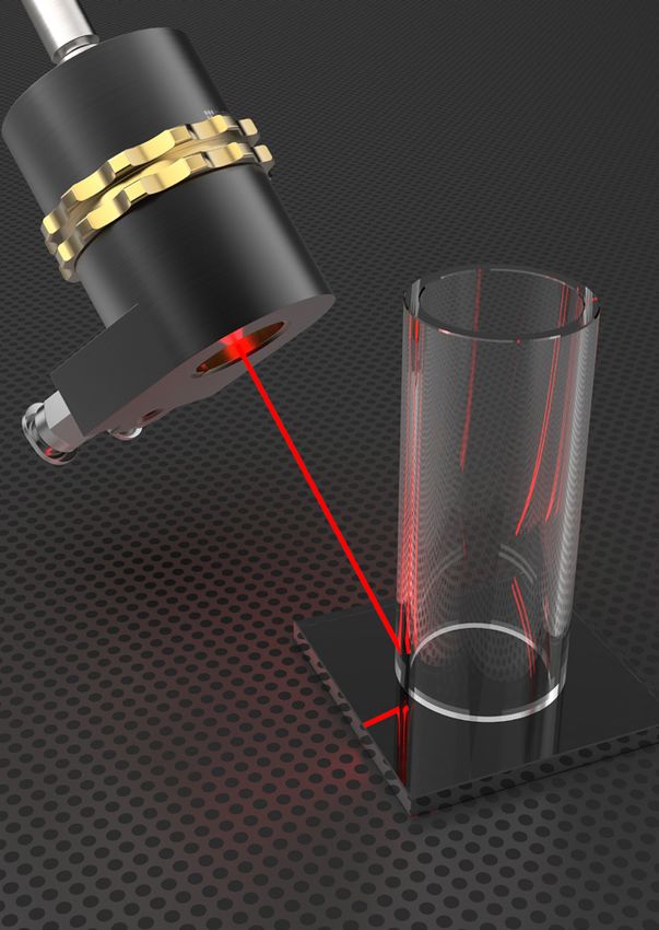
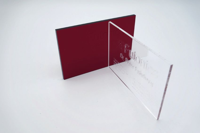
ABOUT FUTONICS

    MANAGING DIRECTOR

Dr. Peter Fuhrberg is the managing director of Fu-      ledge of materials and their processing possibilities
tonics Laser GmbH. After studying physics at the        and developed the IFL product series on this basis.
Technical University of Hannover, he first worked
in research and development at Spindler & Hoyer         The IFL product series consists of high-power pola-
(now Qioptiq, Excelitas Technologies Company)           rized and unpolarized 2.0 µm thulium-doped fiber
and received his doctorate in 1988 in laser physics     lasers with a beam quality of M²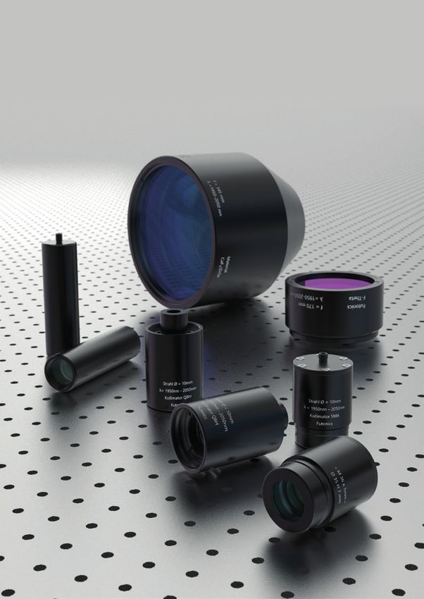
APPLICATIONS

2.0 µm fiber lasers are ideal for welding, cutting,     challenges in welding these structures, especially in
and marking a variety of commercially used plas-        large quantity production environments.
tics as well as for engraving metals, cutting bota-     In consumer electronics, the need for lightweight
nical materials, and labeling food.                     structures with highly customized thermal and
                                                        electrical properties is constantly driving the need
At a wavelength of 2.0 µm, the intrinsic absorption     for more complex designs, often using thin films,
of most thermoplastics is high enough to weld or        and joining dissimilar plastics. The medical device
cut without the need for absorbing additives or         industry is also driving the need to join small plas-
coatings. Compared to commonly used near-infra-         tic parts, often with dissimilar materials.
red systems, welding with 2.0 µm lasers can impro-
ve heat distribution and gap bridging and enable        The growth of laser welding has continued for
the welding and cutting of complex materials.           more than a decade, with the automotive industry
                                                        - an early user of this technology - being the first
The evolution towards the use of lighter and stronger   to recognize the benefits of an automated joining
materials in everyday products, from automobiles to     process combined with the intrinsic advantages of
consumer electronics, has led to several significant    fiber laser technology.

                                                                                                                p. 3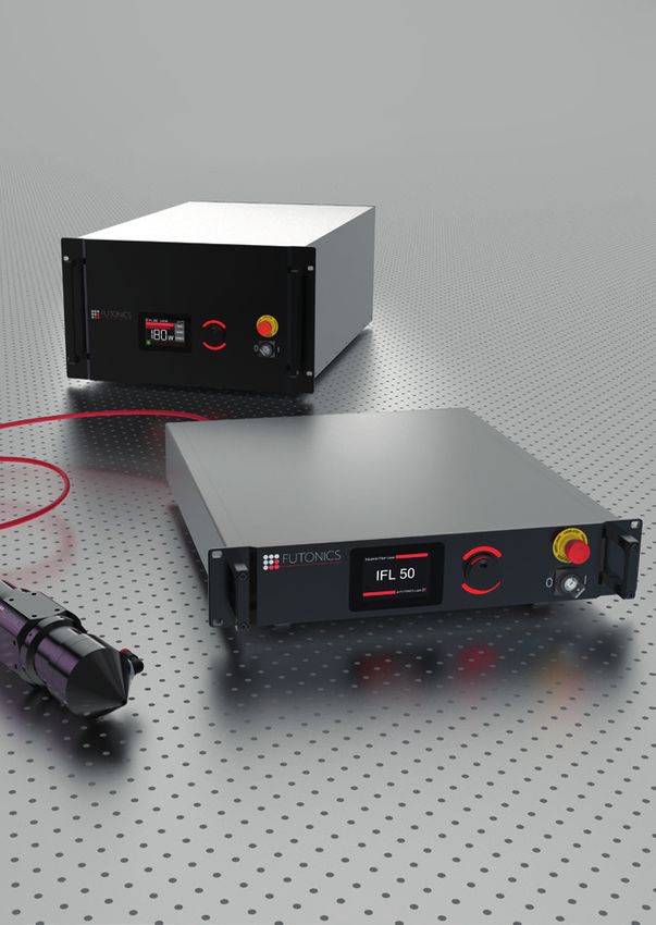
WELDING APPLICATIONS

2.0 µm fiber lasers are well known for their appli-               Volume absorption                            Surface absorption
cation in welding transparent plastics, such as                        a*
A P P L I K AT I O N W e l d i n g A p p l i c a t i o n s L a s e r Tr a n s m i s s i o n W e l d i n g
2.0 µm Tm-doped fiber laser. This further increases Both gaps were closed during the welding pro- LASER TRANSMISSION WELDING
the heat distribution and reduces peak temperatu- cess, but at the shorter wavelength, the absor-
res. As a result, the risk of thermal degradation of bing part is partially burnt, resulting in a gas
the absorbing material is greatly reduced and the bubble in the middle of the weld. In contrast,
Benefits
heat-affected zone is enlarged. Both factors are ad- when using a 2.0 µm laser, the increased thermal
vantageous regarding a major limitation of the wel- expansion of both polymer parts contributes to • Hidden seams
ding process, the limited gap bridging capability. successful gap bridging and no thermal degra- • No particle generation
dation is observed. During cooling, the melt parti-
ally contracts, which leads to the observed „ribs“ • No contamination
Gap bridging in the joining plane. • Non-contact processing of the workpieces
• No mechanical stress on the joining partners
In conventional processes, the transparent part is When T-joint configurations are welded quasi-si-
• No oscillating stress on the joining partners
heated by thermal conduction alone. When ma- multaneously, the joining area can be specifically
nufacturing tolerances, deformed parts, or local designed to have a fusion rib that dramatically • Can be used for both micro and macro
defects cause an air gap between the two compo- increases the gap bridging capability. During the applications
nents, the heat conduction between the two parts welding process, both parts are pressed together • Small heat-affected zone due to locally limited
is greatly reduced and thus the transparent part so that in the areas where there is no gap, the mol-
is not melted, making a welded joint impossible. ten material of the rib is pushed out of the joining energy yield
Since the laser energy cannot be transferred to an area and the two parts approach each other until • No thermal stress of sensitive component areas
adjacent part, the absorbing part becomes hotter all gaps are closed along the entire length of the • No surface markings due to the welding process
than intended and is likely to degrade or partial- weld. Interrupted weld seams can be avoided by
• Great design freedom of the components to be
ly burn. When using a 2.0 µm thulium fiber laser, this procedure.
both components are heated directly by the laser welded
radiation. They expand thermally and thus increa- Other laser sources, such as CO2 lasers, which ope- • Good automation and integration in series Figure 4: Principle of laser transmission welding
se the chance of successful gap bridging. This is rate at about 10.6 µm, would result in direct surface
production
particularly important for plane-to-plane overlap absorption of the radiation, which drastically in-
welding, as used in microfluidics, for example. creases the heat concentration. This would result • Welding of pre-assembled components possible
Figure 3 shows the result of welding tests with a in a high risk of thermal degradation or material • Good external appearance for seams in visible The joint is created directly in the contact zone
quasi-simultaneous welding process for lap welds ablation instead of a controlled and efficient wel- areas by irradiating the surface of the absorbing part
between two polypropylene (PP) parts, in which an ding process. In contrast, the 2.0 µm laser welding through the transparent component and heat
artificial air gap of 130 µm was created with me- of transparent polymers can be applied in various conduction to melt the transparent part. This
tallic spacers. technical fields, such as the manufacture of medi- method is widely used in automotive or consumer
cal and industrial devices or in polymer microflui- Requirements goods production, e.g. for liquid containers or for
dics, where the ability to produce precise hermetic • Polymer compatibility
joining transparent lids to the housing of lighting
welds without any additives is a key factor. Other components. Even though this method does not
• Optical properties
applications can be found, for example, in the food require absorption in the transparent part, the use
• Thermal contact
industry for packaging fresh and ready-to-use food of a 2.0 µm thulium fiber laser proves to be ad-
products. vantageous for these applications. Not only does
Many welding applications for plastics use the laser the fiber laser allow longer working distances and
Below are some examples of welds created du- transmission welding process, in which a transpa- scanner-based beam guidance with smaller spot
ring the welding of polymers. Laser transmission rent part is arranged in an overlap configuration sizes than the commonly used diode lasers due to
welding is particularly emphasized here. 2.0 µm with a second absorbent part, which is usually co- the higher beam quality, the wavelength-depen-
fiber lasers are excellently suited for transmission lored black by the addition of soot to the polymer. dent material properties also lead to direct pro-
welding due to the intrinsic absorption behavior of Figure 4 shows a schematic diagram of the princip- cess improvements. The most obvious difference
Figure 3: Gap bridging for quasi-simultaneous welding of PP common plastics. le of laser transmission welding. in properties is the absorption behavior.
(Technische Hochschule Nürnberg Georg Simon Ohm)
p. 6 p. 7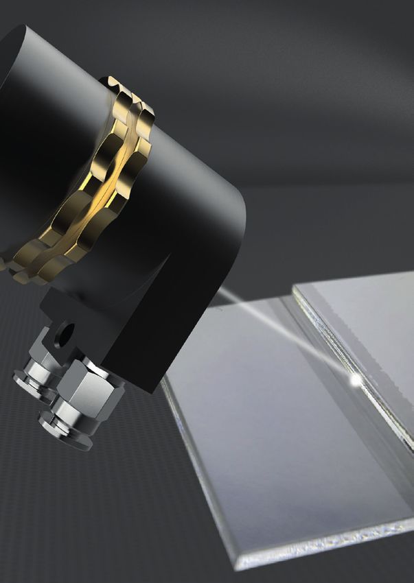
A P P L I K AT I O N W e l d i n g A p p l i c a t i o n s L a s e r t r a n s m i s s i o n w e l d i n g
Wobble Wo
The absorption properties are not the only import- HEAT CONDUCTION WELDING weld seam we
ant aspect in laser transmission welding. At least
as important are the transmission properties of If the transmission of laser radiation of plastics at
the transparent part so that sufficient laser energy the wavelength of 2.0 µm is too low, butt welds Wobble Wo
Wobble Wo
reaches the joining zone between the two parts. can be realized by heat conduction welding. The Circle
weld seam we
The absorption in the transparent parts therefore high energy yield, achieved by very small spot sizes weld seam we
limits the applicability of 2.0 µm laser radiation. For and high laser power, is applied to the surface of
typical applications, however, the material thick- the workpiece, thus creating surface heating. Heat Wobble Wo
Wobble Wo
ness is in the range of a few millimeters, so that suf- conduction allows a weld seam of a few millimeters Linear
weld seam we
ficient radiation reaches the interface between the penetration depth to be realized. weld seam we
two parts and enables the welding process. A ma-
jor problem when welding with conventional lasers In heat conduction welding, the laser melts the Wobble W
Wobble Wo
in the 1.0 µm range can be scattering in the trans- workpiece along the intended seam. The melts Eight
parent part. Additives in the transparent part or of the joining partners flow into each other and weld seam w
weld seam we
even just the crystallite structures in semi-crystal- then cool down to the actual welding seam. Wel-
line polymers can lead to considerable scattering ded joints can thus be realized faster and with less
Wobble W
within the transparent part. This can lead to slight- material distortion than with conventional welding Infinity
ly increased weld seam widths and an increased processes. In addition, smooth and pore-free weld weld seam w
demand for laser power for moderately scattering seams are produced that do not require any post-
materials. With strongly scattering materials, ho- processing. Figure 7: Wobble modes
wever, the beam profile of the laser beam can be
considerably impaired and in the worst case the
laser radiation is isotropically scattered out of the TWIST WELDING PROCESS
joining zone, which makes the welding process im-
possible or severely limits the weldable material TWIST (Transmission Welding by an Incremental Overall, the wobble process allows better tempe-
thickness. Since scattering processes are strongly Scanning Technique) is a low-cost and easy-to-in- rature management of the component, since the
wavelength-dependent, the application of longer tegrate technology based on a beam-wobbling laser beam passes any point on the weld seam se-
laser wavelengths can enable the welding of ma- process. This technique helps to overcome poro- veral times. The temperature increase and cooling
terials that cannot be welded with conventional sity and hot cracking problems in laser welding speeds are slower than with conventional laser
laser sources. of some materials and to suppress sputtering welding, which is helpful in eliminating defects and
during the welding process. With the ability to in- treating spatter. In addition to stabilizing the key-
dependently control penetration depth, wobble hole melt and reducing porosity in the subsequent
frequency, feed rate and seam width, the process weld seam, beam deflection technology has pro-
is used for welding small, temperature-sensitive ven valuable in reducing the requirements for the
assemblies and poorly fitted parts that would be high precision fit of parts during laser welding. The
difficult to weld without post-processing. Figure 7 additional degrees of freedom provided by the in-
demonstrates the concept of dynamic 2D beam dependent amplitude and frequency of the wobble
movement, showing the four basic programmable head oscillation, combined with the high available
shapes of an industry standard welding head. In- power of the fiber laser, provide the level of cont-
dependent control of the amplitude and frequen- rol required for high quality laser welding of diffi-
cy of the oscillation is achieved by a galvo mirror cult materials. In addition, studies comparing the
controller, allowing greater flexibility in stabilizing wobble head with traditional laser welding proces-
the keyhole melt during the welding process. ses have shown that the technology offers signifi-
cant advantages in part fit due to relaxed toleran-
ce in seam gap and misalignment.
Figure 5: Examples for laser transmission welding Figure 6: Microstructures in laser transmission welding
p. 8 p. 9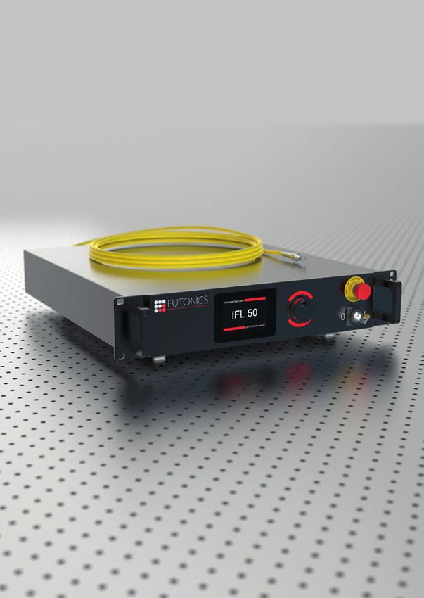
LASER CUTTING APPLICATIONS

The laser systems developed by Futonics can be           Important parameters in laser cutting are focus
used for cutting several different materials. With the   position and diameter (influence power density,
2.0 µm technology it is possible to process complex      gap width as well as the shape of the kerf), output
shapes precisely and quickly. Most materials can         power, operating mode, cutting speed, degree of
be cut without burrs, resulting in less or no rewor-     polarization, process gas and pressure as well as
king of the workpieces. Futonics offers processing       the diameter of the nozzle on the processing head
heads specially developed for cutting materials,         (influences the shape and gas quantity of the gas
which are customized to the users‘ requirements.         jet), through which the process gas is directed onto
                                                         the workpiece. These changeable parameters
                                                         allow the machining process to be optimized. All
    LASER FUSION CUTTING                                 materials that sufficiently absorb the laser radia-
                                                         tion can be cut.
Laser fusion cutting is a non-contact process in
which the workpiece is melted locally by a laser                                        laserbeam

beam.
                                                              cutting gas
                                                                                                       processing head
The material is cut by constant melting of the cut-
ting gap with a low-reaction gas, which removes
the molten material and thus prevents oxidation
of the cutting surface. Nitrogen or argon is often
used as process gas during cutting applications,
which prevents a chemical reaction of the material.
                                                                 workpiece
A post-processing of the cutting edges is not neces-
sary with laser fusion cutting since no burr forma-                                                ejected material

tion at the kerf is produced on the cutting surface
during the process.
                                                         Figure 8: Principle of laser fusion cutting

                                                                                                                         p. 11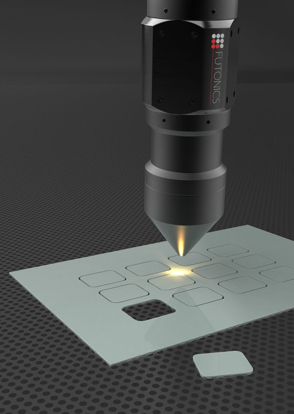
A P P L I K AT I O N L a s e r C u t t i n g A p p l i c a t i o n s
Cutting laminated safety glass Cutting of plastics
Futonics lasers can cut the plastic film between lay- The laser is a very flexible tool that can be used to
ers of glass. In combination with glass cutting tools, cut different polymers with different thicknesses. In
laminated glass can be cut precisely and automa- laser cutting, the cutting gap is very narrow, and
tically in both straight and contoured lines, offering the quality of the cut is very good compared to ot-
a wide range of possibilities for cutting laminated her cutting methods. Depending on the laser cut-
glass. ting system, all materials can be cut. Furthermore,
depending on the material and the laser cutting
process, a clean, narrow, and often rework-free
cutting edge can be achieved. In addition, laser
cutting offers a high material utilization and is the-
refore very economical.
Figure 12: Cut edges of ZeonorFilm ZF14
Cutting of botanical materials
Futonics lasers can be used in botany to cut vari-
ous cellulose-containing samples.
Figure 9: Cutting of laminated safety glass
Cutting of fiber reinforced plastics
Fiber-reinforced plastics are composite materials
in which a polymer matrix is reinforced with fibers
to improve the strength and elasticity of the plastic.
Futonics fiber lasers can produce a highly focused
high-power beam that precisely cuts fiber-reinfor-
ced plastics in a variety of complex shapes.
Figure 10: Cutting of fiber reinforced plastics Figure 11: Cut edge of an 80 µm thick PP-PET film Zoom X/500.0 Figure 13: Cutting of botanical materials
p. 12 p. 13
MARKING, ENGRAVING, LABELLING

     MARKING AND ENGRAVING OF METALS                         ORGANIC LABELLING
     AND POLYMERS
                                                        With Futonics 2.0 µm lasers, fruit, vegetables, and ot-
Laser marking and engraving offers the possibility      her food products are marked safely. The contactless
to apply an uncomplicated, precise and above all        process has no influence on the quality or shelf life of
permanent marking.                                      the food. Especially in retail, food labeling can help to
                                                        avoid unnecessary packaging or labeling materials.
Advantages of marking and engraving of metals           For example, food can be labeled efficiently and qui-
and plastics using a Futonics 2.0 µm fiber laser:       ckly with an organic seal or indication of the country of
                                                        origin. With marking, the label is burned into the peel
                                                        without damaging the fruit pulp.

   Benefits
     • Non-contact marking and engraving
     • In combination with scanner optics: direct
        engraving without stencil
     • No tool change and wear                             Benefits
     • High repetition accuracy with constant                • Use in retail
        engraving quality                                    • Labelling of food
     • Smallest details possible due to very small           • Fruit stays fresh
        spot sizes of the fiber laser                         • Labeling in fruit peel, but not in the pulp

Figure 15: Engraving of black anodized aluminum         Figure 16: Organic labelling on various food items

                                                                                                                    p. 15
LASER SYSTEMS
Futonics offers high-power polarized and unpolari- diodes into the active fiber, specially designed ta-
zed 2.0 µm thulium-doped fiber lasers with a beam pers or combiners are often used. These compo-
quality of M² < 1.1, allowing continuous and modula- nents enable the realization of fiber laser systems
ted operation up to 10 kHz. For a robust and com- with a fiber-only configuration.
pact setup, they are designed in an „all-fiber“ con-
figuration with single-mode fibers and Fiber Bragg
gratings (FBG) and allow the user to order a fixed Cross relaxation
wavelength between 1930 nm and 2050 nm, depen-
ding on the absorption of the materials.
Tm-doped fiber lasers are well suited to generate
high signal powers in the 2.0 µm wavelength range.
By using 792 nm laser diodes for pumping, the up-
energy in cm 1
per laser level is not directly excited, but is populated
by a cross relaxation process (CR) (see Figure 17).
During the CR process an ion from the ground state
is excited to the upper laser level when an ion from
the upper pump level relaxes down to the upper
laser level. Two excited ions were generated by
an absorbed pump photon. This allows high effi-
ciencies for the system, which can be higher than
the limit given by the quantum defect. The 2.0 µm
Tm-laser transition ends in the ground state, which
means that the lower laser level is thermally popu-
lated. To couple the power of fiber-coupled laser Figure 17: Cross-relaxation process
p. 17IFL10 - IFL50
The new industrial fiber laser product line IFL from Futonics is based on thulium-doped single-mode fiber
laser oscillators with wavelength stabilization by Fiber Bragg gratings (FBG). Due to the high beam quality
and the compact design, these new products are ideally suited for a wide range of applications.
IFL10 - IFL50
Output power: 10 W (IFL10), 20 W (IFL20), 30 W (IFL30), 40 W (IFL40), 50 W (IFL50)
Standard wavelengths: 2000 nm or 2050 nm
FWHM: < 1 nm
Beam quality: M2 < 1.1, single-mode
Operating mode: Continuous wave, modulated up to 10 kHz
Laser class: 4
Fiber connector: FC / PC or SMA
NA: 0.15
Length: 5 meters
Collimator: optional
Dimensions (width x height x depth): 483 mm x 88 mm x 505 mm (19″, 2 RU)
Power Supply voltage: 100 – 240 VAC, 50 – 60 Hz
Energy consumption: ≤ 500 W
Control interfaces: Analog, Digital, Serial, Touchscreen
Display: Capacitive 3.5‘‘ touch screen, adjustment wheel
Cooling: Water
Additional fiber length: 1 meter steps up to 20 meter total
Fiber applicator I: Basic collimator
Fiber applicator II: Improved collimator with power detection for regulation
Performance stabilization: Regulation up to 10 kHz
Fixed user-defined wavelength: Selection between 1930 nm und 2050 nm
External power supply: optional
Enhanced interface: Industrial Ethernet on demand
p. 19IFL200 - IFL250
The new industrial fiber laser product line IFL from Futonics is based on thulium-doped single-mode fiber
laser oscillators with wavelength stabilization by Fiber Bragg gratings (FBG). Due to the high beam quality
and the compact design, these new products are ideally suited for a wide range of applications.
IFL200 - IFL250
IFL200 IFL250
Output power: 200 W 250 W
Standard wavelengths: 2000 nm or 2050 nm
FWHM: < 1 nm
Beam quality: M2 < 1.1, single-mode
Operating mode: Continuous wave, modulated up to 10 kHz
Laser class: 4
Fiber connector: Futonics Special, QBH compatible, 5 meters
NA: 0.1
Length: 5m
Collimator: optional
Dimensions (width x height x depth): 483 mm x 266 mm x 703 mm (19″, 6 RU)
Power supply 1: 24 V, 3 Ampere
Power supply 2: 40 V, DC, 33 Ampere 78 Volt DC, 33 Ampere
Energy consumption: ≤ 1,5 kW ≤ 2,8 kW
Control interfaces: Analog, Digital, Serial, Touchscreen
Display: capacitive 3.5‘‘ touch screen, adjustment wheel
Cooling: Water
Additional fiber length: 1-meter steps, up to 10 m in total
Fiber Applicator I: Basic collimator
Fiber applicator II: Improved collimator with power detection for regulation
Performance stabilization: Regulation up to 10 kHz
Fixed user-defined wavelength: Selection between 1930 nm and 2050 nm
External power supply: optional
Enhanced interface: Industrial Ethernet on demand
p. 21IFL10P - IFL30P
The new industrial fiber laser product line IFL from Futonics is based on thulium-doped single-mode fiber
laser oscillators with wavelength stabilization by Fiber Bragg gratings (FBG). Due to the high beam quality
and the compact design, these new products are ideally suited for a wide range of applications.
Polarized fiber lasers offer a very good protection against back reflections, which is especially interesting
for processing highly reflective surfaces. In scientific applications the polarized lasers can be used as pump
source for polarization dependent laser crystals, e.g. holmium.
IFL10P - IFL30P
Output power: 10 W (IFL10), 20 W (IFL20), 30 W (IFL30)
Standard wavelengths: 2000 nm or 2050 nm
FWHM: < 1 nm
Beam quality: M2 < 1.1, single-mode
Operation mode: Continuous wave, modulated up to 10 kHz
Laser class: 4
Fiber connector: FC / PC oder SMA
NA: 0.15
Length: 5 meters
Collimator: optional
Dimensions (width x height x depth): 483 mm x 102 mm x 505 mm (19‘‘, 2 RU + feet)
Power supply voltage: 100 – 240 VAC, 50 – 60 Hz
Energy consumption: ≤ 500 W
Control interfaces: Analog, Digital, Serial, Touchscreen
Display: Capacitive 3.5‘‘ touch screen, adjustment wheel
Cooling: Water
Additional fiber length: 1-meter steps, up to 20 m in total
Fiber applicator I: basic collimator
Fiber applicator II: Improved collimator with power detection for regulation
Power stabilization: Regulation up to 10 kHz
Fixed user-defined wavelength: Selection between 1930 nm and 2050 nm
External power supply: optional
Enhanced interface: Industrial Ethernet on demand
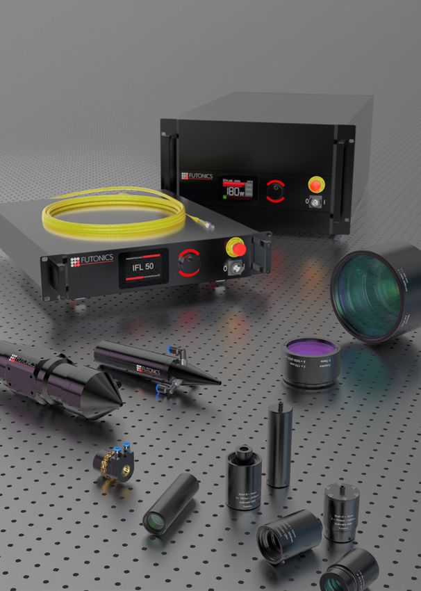
p. 23OPTICAL SYSTEMS
For welding, cutting, marking, and engraving applications, Futonics offers customized optical systems
designed to meet the requirements of the user. These include scanner systems (consisting of two mirrors
to guide the laser beam) with F-Theta optics and processing heads (with or without integrated cooling
system) for welding and cutting applications. For customized applications, optics optimized for medium
IR wavelengths including collimators, focusing lenses and complete setups can be supplied.
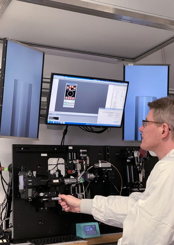
Scanner systems can be upgraded with pilot lasers, pyrometers, or camera systems. The camera system
identifies the structure of the workpiece to automatically detect the position of the weld seam. Laser con-
nectors like Futonics Special, FC/PC, SMA or QBH compatible are available.
p. 25OPTISCHE SYSTEME C o l l i m a t o r s
COLLIMATORS
Laser collimators are an indispensable accessory for the integration of lasers into higher-level machine
units. It is essential to have a collimated laser output both for the coupling in and out of light from or into
an optical fiber. With the help of an optical collimator, the divergence of the light output can be significant-
ly reduced. Based on this requirement, Futonics has developed its own collimator systems. By using optical
infrared materials, beam quality and efficiency are maximized. The product design is compact, easy to
use and suitable for various optical applications.
Collimators
Specifications Futonics 12.0 Futonics 16.4 Futonics 18.0 QBH 10.0 SMA 2.0 SMA 8.8 SMA 10.0 SMA 12.7
Wavelength [nm] 1940 – 2050 1940 – 2050 1940 – 2050 1940 - 2050 1940 – 2050 1940 – 2050 1940 – 2050 1940 - 2050
Effective focal length [mm] 44.5 83.3 64.4 49.7 6.9 44.5 35.7 64.4
Beam diameter (1/e²) [mm] 12.0 16.4 18.0 10.0 2.0 8.8 10.0 12.7
NA 0.14 0.10 0.14 0.10 0.14 0.10 0.14 0.10
Fiber Connector Futonics Futonics Futonics QBH SMA SMA SMA SMA
Housing size [mm x mm] 117 x 30 117 x 30 117 x 30 68 x 43 48 x 39,6 117 x 30 60 x 39 117 x 30
Weight [g] 112 114 114 90 110 112 172 114
Suitable for laser output [W] 200 200 200 200 50 50 200 50
* Theoretical beam properties at the collimator output
p. 26 p. 27O P T I S C H E S Y S T E M E F -T H E TA L e n s e s
Design wavelengths
1940 nm – 2050 nm F-THETA LENSES
F-TO 345/2000 F-TO 170/2000
In most cases, an f-theta lens is installed behind a moving galvanometer mirror system to realize various
applications such as marking, drilling, welding, scribing, and cutting. The f-theta lens, in combination with
the XY-galvo scanner unit, creates a two-dimensional work area in which any contour can be mapped.
The lenses are diffraction limited and are characterized by high imaging quality. In addition, they offer a
high damage threshold, high spot constancy over the entire scan area and guarantee a minimal focal
point shift for high-power lasers.
Futonics offers different f-theta lenses for the near infrared wavelength range. The new product line is ba-
sed on crystal lenses made of zinc selenide (ZnSe) and calcium fluoride (CaF2 ). Available are focal lengths
of 170 mm (scanning field 90 mm x 90 mm) and 345 mm (scanning field 205 mm x 205 mm). The extremely
Spot diameter [µm] as a function of optical scan angle [°]. Diameter of the entrance beam
(1/e²): 10 mm (F-TO 345/2000) or 7.5 mm (F-TO 170/2000)
versatile possibilities of the fiber laser can only be fully exploited by providing focusing systems suitable
for manufacturing. The Futonics f-theta lenses for laser material processing guarantee best processing
results over the entire working area. Especially in demanding applications, these lenses can help to meet
your manufacturing requirements. The wide range of applications includes: Laser material processing,
Automotive Industry, Medical Technology, Solar cell production, Semiconductor Manufacturing
F-TO 345/2000 F-TO 170/2000
Design wavelength [nm] 1940 – 2050 Design wavelength [nm] 1940 – 2050
Effective focal length [mm] 344.8 Effective focal length [mm] 170.2
Entrance beam diameter (1/e²) [mm] 10 Entrance beam diameter (1/e²) [mm] 7.5
Scan area [mm²]* 205 x 205 Scan area [mm²]* 90 x 90
Working distance [mm] 319.5 Working distance [mm] 198,8
Flange - focus distance [mm] 468.4 Flange - focus distance [mm] 242.8
Optical scan angle [°] ±24 Optical scan angle [°] ±22
Mirror - flange distance [mm] 48.4 Mirror - flange distance [mm] 30.5
Spot diameter focus (1/e²) [µm] 87.8 Spot diameter focus (1/e²) [µm] 57,8
Max. telecentricity error [°] 14.6 Max. telecentricity error [°] 11.5
Lens material ZnSe, CaF2 Lens material ZnSe, CaF2
Cover glass CaF2 Cover glass CaF2
AR-Coating VIS (600 - 700 nm) T>80%, AR-Coating VIS (600 - 700 nm) T>80%,
AR-Coating Laser (1940 - 2050 nm) T>99%, AR-Coating Laser (1940 - 2050 nm) T>99%,
AR-Coating Pyrometer (3,5 - 5 µm) T>60% AR-Coating Pyrometer (3,5 - 5 µm) T>60%
Weight [kg] 4.5 Weight [kg] 0.8
Mounting thread [mm] M85 x 1 Mounting thread [mm] M85 x 1
* For a system with two mirrors with mirror distances from the lens housing: 19.7 mm / 35.7 mm * For a system with two mirrors with mirror distances from the lens housing: 19.7 mm / 35.7 mm
All product information is believed to be correct and can be obtained without expectation. The information connected here is only legally
binding for Futonics if it is contained in the terms and conditions of a sales contract. The user must have all rights and rights related to the
management of a contact or its application. © 2020 Futonics Laser GmbH. All rights protected.
p. 28 p. 29PROCESSING HEADS
Futonics offers a comprehensive range of optical processing heads to efficiently optimize fiber laser
applications in precision cutting and welding. The Futonics laser processing heads can work with a
5-axis system or a robotic arm to follow irregular geometries. Our fiber lasers offer high quality beams
to meet your different needs for different processing scenarios. The futonics laser head with precision
optical design improves product quality, increases performance, and makes it easier to manufacture
precision products.
p. 31OPTical SYSTEMS P ro c e s s i n g H e a d s F M H 1 0 0 0/ 1 0 0 0
FMH980/1000
The processing head FMH980/1000 was developed by Futonics for welding applications. The welding
head has a variable working distance up to collimation, which can be adjusted for the respective applica-
tion via the setting wheel. At the minimum focal length of 25 mm the spot diameter is 50 µm, at collimation
1.93 mm. The processing head is designed with an SMA fiber connector to couple the laser.
FMH980/1000
Wavelength [nm] 1940-2050
Working distance [mm] 980
Beam diameter focus (1/e²)* [µm] 1000
NA Input 0.14
NA Output 0.0006
Fiber Connector SMA
Housing size [mm x mm] 48.5 x 39.6
Weight [g] 110
Suitable for laser power [W] 50
Application Welding
* with single-mode fiber with NA Input = 0,14
16,00
,00
R17
48,00
42,50 30,00
p. 32 p. 33
0,00O P T I C A L S Y S T E M S P r o c e s s i n g H e a d s F M H 1 6 0 /4 0
FMH46/45
The processing head FMH46/45 can be used to cut various materials. It has a working distance of 46
mm and a beam diameter of 45 µm in focus. The process gas can be fed into the cutting head through
cooling connections. The user can choose between one to three cooling connections for the cutting ap-
plication. Lasers can be coupled into the processing head through either an SMA, Futonics Special or QBH
compatible fiber connector.
FMH46/45
Wavelength [nm] 1940-2050
Working distance [mm] 46
Beam diameter focus (1/e²)* [µm] 45
NA Input 0.14
NA Output 0.03
Fiber Connector SMA/Futonics/QBH
Housing size [mm x mm] 250 x 43.1
Weight [g] 560
Suitable for laser power [W] 200
Application Welding
* with single-mode fiber with NA Input = 0,14
3 Cooling instruction 2 Cooling instructions 1 Cooling instructions
43,00
43,00
244,50
244,50
p. 34 p. 35OPTICAL SYSTEMS P ro c e s s i n g H e a d s F M H 1 0 0/ 9
FMH9/14
The processing head FMH9/14 can be used to cut various materials. It has a working distance of 9 mm
and a beam diameter of 14 µm in focus. The process gas can be fed into the cutting head through a
cooling connection. Lasers can be coupled into the processing head through either an SMA, Futonics
Special or QBH compatible fiber connector.
FMH9/14
Wavelength [nm] 1940-2050
Working distance [mm] 9
Beam diameter focus (1/e²)* [µm] 14
NA Input 0.14
NA Output 0.09
Fiber Connector SMA/Futonics/QBH
Housing size [mm x mm] 448 x 99.96
Weight [g] 1600
Suitable for laser power [W] 50/200
Application Cutting
* with single-mode fiber with NA Input = 0,14
90,25
70,00
494,00 70,00
p. 36 p. 37OPTICAL SYSTEMS I n s t a l l a t i o n s
INSTALLATIONS ACCESSORIES
Futonics also offers customized material processing
assemblies for the respective application area.
Working fibers
Fiber NA 0.22/0.45 0.22 ± 0.02
Fiber Core [µm] (± 3 - 5 µm) 100/200/400/600/800/1000 1000
Fiber Cladding [µm] (± 3 - 5 µm) 105/220/440/660/880/1100 1100
Fiber Coating [µm] (± 3 - 5 µm) 125/320/700/960/1100/1600 1600
Fiber material Low OH Quartz (SiO2) Low OH Quartz (SiO2)
Cladding material Fluoride doped Quartz Fluoride Doped Quartz
Coating material Acrylate Acrylate
Protection cable material Interlock stainless steel Interlock stainless steel
Protection cable outer diameter [mm] 6.2 6.2
Protection cable color Yellow Yellow
Connector both sides Standard SMA Standard SMA
Length [m] 10 10
Operating temperature [°C] -40 - 85 -40 - 85
Bending radius [mm] ≥ 200 times cladding diameter Short-term: ≥ 220
Long-term: ≥ 110
p. 38 p. 39Futonics Laser GmbH Albert-Einstein-Str. 3 37191 Katlenburg-Lindau Deutschland Tel: +49 551 504207-0 Fax: +49 551 504207-20 info@futonics.de www.futonics.de
You can also read