Cold atoms in micromachined waveguides: a new platform for atom-photon interactions
←
→
Page content transcription
If your browser does not render page correctly, please read the page content below
Cold atoms in micromachined waveguides: a new platform for atom-photon
                                                  interactions
                                                           E. Da Ros,1 N. Cooper,1, a) J. Nute,1 and L. Hackermueller1
                                                          School of Physics and Astronomy, University of Nottingham, Nottingham, NG7 2RD, United Kingdom
                                                          (Dated: 8 May 2020)
                                                          Hybrid quantum devices, incorporating both atoms and photons, can exploit the benefits of
                                                          both to enable scalable architectures for quantum computing and quantum communication,
                                                          as well as chip-scale sensors and single-photon sources. Production of such devices depends
                                                          on the development of an interface between their atomic and photonic components. This
                                                          should be compact, robust and compatible with existing technologies from both fields. Here
arXiv:1906.06236v2 [physics.atom-ph] 7 May 2020

                                                          we demonstrate such an interface. Cold cesium atoms are trapped inside a transverse, 30 µm
                                                          diameter through-hole in an optical fiber, created via laser micromachining. When the guided
                                                          light is on resonance with the cesium D2 line, up to 87% of it is absorbed by the atoms. The
                                                          corresponding optical depth per unit length is ∼ 700 cm−1 , higher than any reported for a
                                                          comparable system. This is important for miniaturization and scalability. The technique can
                                                          be equally effective in optical waveguide chips and other existing photonic systems, providing
                                                          a new platform for fundamental research.

                                                  I.   INTRODUCTION                                                centre of the propagating mode of the waveguide and
                                                                                                                   hence enables good coupling between photons and atoms.
                                                     Interfacing cold atoms with optical waveguides has been       It has been shown that with the addition of an optical
                                                  a very active field of research over the past two decades1–7 .   cavity strong coupling between the atoms and the guided
                                                  This has been motivated by the great potential of hybrid         light is achievable in such systems28 . The technique can
                                                  atom-photon systems for sensing, quantum communica-              be extended to multiple holes in a single waveguide, thus
                                                  tion and quantum information processing2,8–10 . Existing         allowing atoms at different sites to be coherently coupled
                                                  approaches tend to involve purpose designed systems              via the optical field.
                                                  such as tapered nanofibres11–15 , hollow-core fibres16–20           We provide an experimental demonstration of the above
                                                  or other custom-built waveguide and photonic crystal             technique within a standard, single-mode optical fiber
                                                  structures21,22 , which don’t lend themselves readily to         (Thorlabs 780HP). A cloud of cold Cs atoms is guided
                                                  integration. Herein we describe a universal technique,           into 30 µm diameter cylindrical through-hole, drilled or-
                                                  capable of interfacing cold atoms with nearly any ex-            thogonally to the core of the fiber. The atoms absorb 87%
                                                  isting waveguide system. This new approach will allow            of the optical power of a resonant probe beam traveling
                                                  hybrid devices to take full advantage of the capabilities        through the fiber.
                                                  of all-optical waveguide chips, which have reached a very           The small size of the interaction region, which is some
                                                  high level of development23–25 . The increased range and         tens of micrometres in length, is a clear advantage over
                                                  complexity of operations thus permitted can be expected          existing methods, e.g. many fibre-based experiments in-
                                                  to greatly expand the potential of hybrid atom-photon            volve interaction regions with lengths on the centimetre
                                                  devices, opening the door to long-standing experimental          scale. We measure the optical depth per unit length of
                                                  and technological goals1,2,8,9 .                                 our trapped atom cloud at ∼ 700 cm−1 , greater than any
                                                     The basis of the technique described herein is the intro-     value found in the literature for a comparable system29,30 .
                                                  duction of cold atoms into microscopic, laser-drilled holes      This has important benefits for device miniaturisation,
                                                  in optical waveguides, see Fig. 1(a) and 1(b). Laser mi-         enabling scalability of the number of waveguide-atom
                                                  cromachining can be used to create holes at any desired lo-      interfaces within a small device and improving spatial
                                                  cation(s) within a very wide range of materials, including       resolution in sensing applications8 . In the directions trans-
                                                  most glasses and ceramics, silicon, metals and polymers26 .      verse to the propagation axis, the interface retains the
                                                  This is a significant advantage over techniques linked to        small mode area of the waveguide. The tight confinement
                                                  specific waveguide materials and architectures, as it will       of the light while traversing the interaction region natu-
                                                  allow the method to be applied easily across a broad             rally helps to achieve strong atom-photon coupling17,31 .
                                                  range of waveguide devices and to take full advantage of            The technique permits large atom-surface separations.
                                                  advances in subwavelength integrated optics and optical          This diminishes the influence of decoherence and line-
                                                  metamaterials27 . Furthermore, the shape of these holes          broadening effects caused by atom-surface interactions,
                                                  can be controlled and modified according to the needs of         enabling the use of charged or highly polarisable particles.
                                                  the user28 , see Fig. 1(c).                                      Rydberg atoms are an important example of such polar-
                                                     Drilling a transverse hole through an optical waveguide       isable particles, with significant applications for sensing
                                                  allows cold atoms to be directly overlapped with the             and multi-qubit atomic gate operations32,33 .
                                                                                                                      Furthermore, the ability to hold the atoms within the
                                                                                                                   interaction region for a prolonged period using an optical
                                                                                                                   dipole trap allows sequential or time-separated operations.
                                                  a) nathan.cooper@nottingham.ac.uk
                                                                                                                      Overall, the approach described herein results in a com-
2
(a) (c) (d)
z y
125 μm
30 μm 30 μm
x x
OD
(e)
Fibre
Optical
(b) Dipole trap
(f) MOT beam
Probe
SPCM
MOT beam
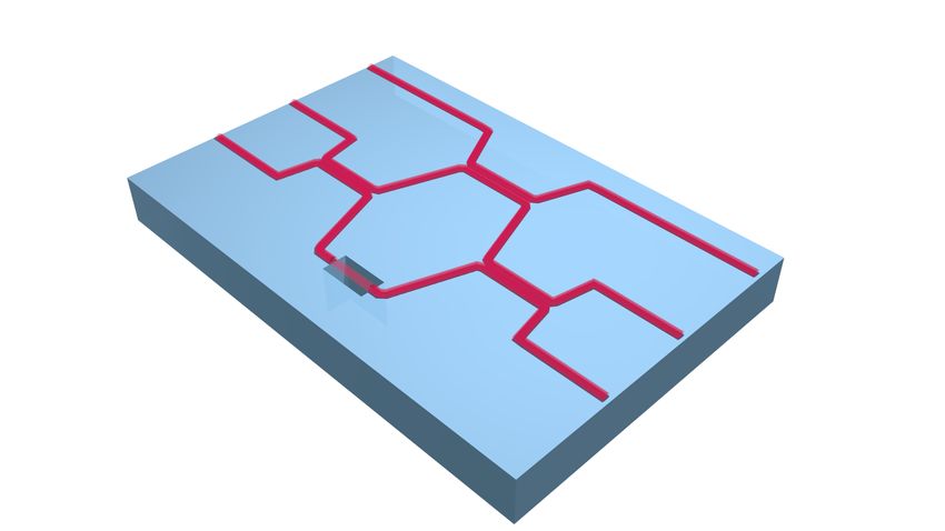
Fig. 1. (a), Illustration of an atom cloud confined within a microscopic hole in an optical fiber using an optical dipole trap (red
beam) and interfaced with light guided in the fiber (blue beam). (b), Illustration showing the proposed use of this technique for
the inclusion of cold atoms in a waveguide chip. (c) and (d), Examples of differently shaped laser drilled holes and side and
top view of the hole used in this study, images by Workshop of Photonics. (e), Absorption image of cesium atoms confined
in an optical dipole trap aligned with the void in the fiber (fiber visible as a horizontal feature at the center of the image).
f, Schematic of the setup (top view). Atoms are trapped in a magneto-optical trap below the interface, then guided to the
interaction region via an optical dipole trap. Here they are probed by light propagating in the fiber (blue beam). The output is
collected by a single photon counting module.
pact, robust interface that can be directly inserted wher- atoms are also optically pumped to the {62 S1/2 , F = 4}
ever it is needed within an existing waveguide architecture. state. At the same time the magnetic field gradient used
Our results represent an important advance towards the to generate the MOT is ramped down and the magnetic
goal of combining cold atoms and optical waveguides into field center is displaced upwards by increasing an offset
an integrated and scalable quantum device. field. This transport technique allows us to achieve an
atom density n ≈ 5 × 10¹⁰ atoms/cm3 immediately below
the hole in the fiber.
II. EXPERIMENTAL REALISATION A fiber laser with a wavelength of 1064 nm and a
maximum power of 25 W is used to create an optical
dipole trap for the atoms. The trap consists of a vertical
Our experimental setup is illustrated in Fig. 1. The
beam which is focused down to a waist of 13 µm and
interface is based on a commercially available single mode
aligned through the hole in the optical fiber, see Fig. 1(e).
optical fiber with a mode field diameter of (5.0 ± 0.5) µm
The focal point lies within the interaction region. After
at 850 nm and a cladding diameter of 125 µm. The
switch-off of the MOT beams, a hold-time of 3 ms allows
fiber has been laser drilled with a cylindrical through hole
the atoms to migrate along the dipole trap beam into the
perpendicular to the light propagation axis, with diameter
interaction region.
D = 30 µm, as shown in Fig. 1(d). Laser drilling was
performed by Workshop of Photonics. Pulses of probe light are sent through the fiber so
For mounting purposes, the fibre is attached to a glass that they interact with the atoms. For this we use light
slide, which is then placed into a vacuum chamber. The resonant with the |gi = {62 S1/2 , F = 4} −→ |ei =
fibre enters the vacuum system through custom built {62 P3/2 , F = 5} transition of 133 Cs. One microsecond
fibre-feedthroughs34 and the region containing the hole is before the probing pulse, the dipole trapping beam is
suspended in the center of the vacuum chamber. Approx- switched off. The output of the optical fiber is directed
imately 3 × 10⁷ 133 Cs atoms are loaded into a magneto- onto a single photon counting module (SPCM), as shown
optical trap (MOT), about 1 mm below the fiber. To cool in Fig. 1(f ), which is used to determine the number of
the cloud further, the trapping lasers are then detuned by transmitted photons.
13 Γ in an 18 ms optical molasses stage (where Γ is the In order to measure the fraction of the probe light
natural linewidth of the transition). During this time the absorbed by the atom cloud, we count the number of3
photons received during a 15 µs probe beam pulse. We
then repeat the measurement after a 100 ms delay, during Fit to eq.(1)
which the atoms are dispersed. The absorption fraction Data
is determined from the ratio of the two results. In order
to avoid saturating the atomic transition, very low probe
beam powers (on the order of pW) are necessary, and as
a result photon counting statistics become our dominant
source of experimental random error, see Appendix C. We
average multiple measurements (typically between 30 and
100) for any given set of experimental conditions, thus
reducing the statistical uncertainty.
III. RESULTS
Using a probe beam power Ppr = 13 pW, we measured Fig. 2. Fractional absorption of the probe beam light by
(87 ± 2)% absorption caused by the atoms, corresponding the atoms as a function of the detuning δ from the |gi =
to an optical depth (OD) of 2.1 ± 0.2, leading to an opti- {62 S1/2 , F = 4} −→ |ei = {62 P3/2 , F = 5} 133 Cs transition.
cal depth per unit length of 700 cm−1 . This implies the Each point corresponds to the mean of 36 repetitions, with
presence of 290 ± 20 Cs atoms in a volume of 600 µm3 the error bars representing the standard deviation. The solid
and corresponds to an average density on the order of line is a fit according to eq. (1).
5 × 10¹¹ atoms/cm3 , assuming a uniform atomic distribu-
tion across the interaction region. These values therefore
represent a lower limit on the atom number and peak intensity I of the light traversing the atom cloud will obey
density. the differential equation
The response of the atomic absorption to changes in dI(x, y, z) I(x, y, z)
probe laser detuning, probe laser power and dipole laser = −nσ0 . (2)
dx 1 + I(x,y,z)Isat
power was measured. Fig. 2 shows the fractional ab-
sorption of the probe beam power by the atom cloud where n represents the mean atomic density in the
as a function of the probe laser detuning δ, as the laser interaction region and σ0 represents the atomic absorp-
frequency is tuned across the {F = 4} −→ {F 0 = 5} tion cross section on resonance. The atomic density can
transition. The probe beam power was Ppr = 9 pW. The be approximated as uniform along the y and z direc-
resonance profile derives from the natural linewidth of the tions, see Appendix B. The distribution of the atoms
atomic transition Γ, with the atomic absorption response along the x axis, while non-uniform, does not affect the
in percent given by17 final light intensity resulting from our model. We solve
!! eq. (2) numerically for I(D, y, z), the probe light intensity
−OD transmitted through the hole at position (y, z), where the
Abs = 100 1 − exp . (1) incident optical intensity I(0, y, z) is given by the input
1 + 4( Γδ )2
power P and the mode profile of the fiber. We assume
This model is valid in the limit of low atomic saturation that, in the z axis as shown in Fig. 1(d), the propagating
(i.e. the intensity of the probe light, I, must be very much light mode of the fiber is not significantly altered as it
lower than the saturation intensity, Isat of the atomic traverses the void. In the y axis, the curvature of the hole
transition), which is fulfilled in this case. The green line acts as a cylindrical lens, leading to a divergence of the
in Fig. 2 represents a fit of eq. (1) to the experimental propagating beam mode. To account for this we use a
data, where natural linewidth and optical depth have simplistic model, where it is assumed that light incident
been used as free parameters. This fit results in values too far from the fiber axis, at coordinates with |y| greater
of OD= 1.9 ± 0.2 and Γ= 2π × (5.5 ± 0.4) MHz. The than a cut-off distance cy , will not be coupled back into
experimentally derived value for Γ is in good agreement the guided mode on the other side of the void. The cut-off
with the theoretical value of 2π × 5.2 MHz, proving that distance cy is then used as a free parameter when fitting
the atomic transition is not noticeably broadened by the the data to the model.
presence of the fiber. Integrating over the dimensions (y,z) then results in
The dependence of the atomic absorption response on the total absorption:
the probe beam power was characterized and the results Zcz Zcy
are shown in Fig. 3. The fact that, in this case, neither 1
Abs = 1 − I(D, y, z) dydz, (3)
the optical depth nor the ratio of the probe beam intensity P
−cz −cy
to the atomic saturation intensity can be approximated
as small necessitates a numerical approach to modeling where P is the total power within the integration area
this situation.
Consider an element of the incident intensity distri- Zcz Zcy
bution at a specific position I(0, y, z). Employing the P = I(0, y, z) dydz, (4)
standard assumption of direct ray propagation35,36 , the −cz −cy4
1.2
Fit to eq.(3) 1
1.0 Data
Trap depth [mK]
Relative absorption
0.8
Relative absorption
2.0 0.0
0.8
1.5 -0.5
-1.0
0.6 1.0
0.6 -1.5
z pos. [mm]
0.5
-2.0
0.0
0.4
0.4 -2.5
-0.5 -3.0
-1.0 -3.5
0.2 0.2 -1.5
-4.0
-4.5
-2.0
-30 -20 -10 0 10 20 30
0 0 x pos. [µm]
100 101 102 103 104 0 5 10 15 20 25
Probe beam power [pW] Dipole beam power [W]
Fig. 3. Relative absorption of resonant probe light as a Fig. 4. Relative absorption of resonant probe light as a
function of the incident probe beam power. Each point cor- function of the power in the optical dipole trapping beam.
responds to the mean of 49 repetitions, with the error bars Each point corresponds to the mean of 49 repetitions, with
representing the standard deviation. The solid line is a fit the error bars representing the standard deviation. The line
according to eq. (3). plot is a guide to the eye. In the inset the trapping potential
is depicted for 5 W of trapping power. The asymmetry in the
plot is due to gravity.
cz is taken to be large compared to the mode radius of
the fiber, and I(0, y, z) takes into account the Gaussian
distribution of the probe beam intensity. optical depth per unit length. This technique will have
Fitting the data to this model, with the atom den- important applications in the production of miniaturized
sity n and the y cut-off distance cy as free parameters, atom-optical devices for sensing, quantum communication
gives the theoretical fit plotted in Fig. 3. The result- and quantum information processing.
ing value cy = (1.9 ± 0.3) µm is comparable to the Demonstration of this technique within a more com-
fibre mode radius, as expected. The corresponding atom plex waveguide network, together with its use to produce
density n ≈ (2.9 ± 0.1) ×1011 atoms/cm3 implies the coherent atom-optical effects such as electromagnetically
presence of 170 ± 5 atoms in the interaction region. We induced transparency37 or four-wave mixing38–40 , rep-
assume that the light reaching the atoms is linearly po- resents the next step towards a quantum information
larized, and use the corresponding saturation intensity processing device based on this architecture.
Isat = 1.66 mW/cm2 , although small deviations from We have shown in28 that appropriate shaping of the
this are possible as the fiber is not polarization main- micromachined holes can lead to very high transmissions
taining. Finally, the absorption of the probe beam was comparable to existing interfaces. New holes with tailored
measured as a function of the power used in the dipole shapes leading to higher transmission efficiencies are go-
trapping beam, as shown in Fig. 4. The results show that, ing to be implemented in future designs of the interface.
for powers in excess of 5 W (corresponding to trapping The reduced optical losses make conceivable to introduce
frequencies of νr ≈ 76 KHz in the radial direction and optical cavities around such holes, for example via the
νz ≈ 2.0 KHz in the longitudinal direction), the number use of laser written Bragg gratings in the waveguides41,42 ,
of atoms loaded into the interaction region is no longer with a sufficiently high finesse to bring the atom-light sys-
limited by the power of the dipole trapping beam. This tem into the strong coupling regime43 . For atom numbers
indicates that for powers larger than 5 W the depth of comparable to those demonstrated here, we find that co-
the optical dipole trap has become large compared to the operativities on the order of C = 400 should be possible28 .
temperature of the atomic cloud. The fact that the probe This would enable photonically-mediated interactions be-
absorption appears to drop to zero for finite dipole beam tween atoms located at distant sites, and also permits
powers is expected given the influence of gravity on the single photon gate operations. The technique thus has
trapping potential. the potential to directly interface photonic and atomic
qubits.
IV. CONCLUSIONS AND OUTLOOK
ACKNOWLEDGMENTS
We have demonstrated efficient coupling of a cold
atomic ensemble, introduced into a laser-micromachined The authors would like to thank E. Haller, K. Poulios, P.
hole in an optical waveguide, to the central mode of the Verlot, G. Buonaiuto and the ErBeStA team for useful
light guided in the waveguide. This method for interfacing discussions. This project was supported by the EPSRC
atoms and waveguides enables the establishment of new grants EP/R024111/1, EP/K023624/1, EP/M013294/1
atom-photon interaction platforms. It is applicable within and by the European Commission grants QuILMI (no.
a wide range of waveguide architectures and offers high 295293) and ErBeStA (no. 800942). We acknowledge5
support from the University of Nottingham through a with unbalanced ramps, modifying the field gradient in
Birmingham-Nottingham collaboration grant. the region of the cloud. Simultaneously the magnetic
offset field increases and the cloud is pushed upwards.
The presence of the glass plate and the scattering arising
V. AUTHOR CONTRIBUTIONS from the mechanically drilled hole in the mounting plate
adversely affect the MOT beams and hence the MOT
L.H. conceived the experiments and oversaw the work. loading. The closer the starting position of the trap is
System construction and testing was commenced by J.N. to the surface of the chip, the lower the achievable atom
and N.C. and completed by N.C. and E.D.R.. E.D.R. con- density is. The transport stage is therefore necessary to
ducted the experiment and collected the published data, obtain a dense, cold cloud close to the fiber.
with assistance from N.C.. E.D.R. and N.C. wrote the The optical dipole trap is switched on 42 ms before the
paper with assistance from L.H.. All authors contributed start of the optical molasses stage. The resulting 60 ms
to the manuscript, E.D.R. and N.C. contributed equally of overlap between the dipole trap and the MOT stage
to this work. was found to maximize the dipole trap loading and the
final atom number at the position of the fiber core.
The atoms are assumed to have a uniform distribution
Appendix A: Interface details in the y and z directions. This is an reasonable assumption
in our experiment, as both the Rayleigh length and the
waist of the dipole trapping beam substantially exceed
Prior to laser machining, a commercially available Thor-
the diameter of the probe beam.
labs 780HP bare fiber is glued underneath a glass plate,
using vacuum compatible UV-cure glue (Dymax Low-
Shrink OP-67-LS). A 1 mm diameter, mechanically drilled
hole in the glass plate allows unobstructed passage of the Appendix C: Measurement methods
dipole and imaging beams through the interaction region.
Following micromachining of the fiber, the chip is sus- Between 1 and 104 pW of probe light is coupled into the
pended in the center of the vacuum chamber, with the optical fiber, and the fiber output is then focused onto the
central region of the fiber free-hanging for approximately photoreceptor of a single photon counting module (Exceli-
5 mm. tas SPCM-AQRH-14). The number of photons reaching
In reference28 we describe how, with appropriate shap- the SPCM is recorded using high frequency binary counter
ing, microscopic holes of the kind used herein can allow chips connected to an Arduino Uno. A linearity correction
very high optical transmission efficiencies, comparable to function, specified by the manufacturer, is employed to
similar platforms. For example, with a minimum separa- account for the influence of the receptor dead time at
tion of 30 micrometers between the two faces of the hole high count rates.
> 90% power transmission is possible, with the dominant In each experimental cycle, two readings are taken from
source of loss being reflections at the fibre to hole inter- the SPCM: the number of photons received with atoms
faces. Our first prototype device employs a cylindrical present in the hole, Nat , and the number received without
hole and consequently offers a much lower transmission atoms, Nbgd . In both cases, the duration of the probe
efficiency of ∼ 20%. This results from a theoretical trans- pulse is 15 µs, with 100 ms allowed between the two pulses
mission efficiency of 31% with the additional losses due to for the atoms to disperse.
surface roughness inside the hole. Both of these problems Unwanted SPCM counts arising from background light
are surmountable in future iterations, with micromachin- sources and scattered dipole trap light are minimized us-
ing of more favourable hole shapes having recently been ing a laser-line filter (SEMROCK LL01-852), positioned
accomplished (as shown in Fig. 1(c)) and transmissions directly in front of the SPCM, and appropriate physi-
close to the theoretical optimum for their chosen hole ge- cal shielding. To compensate for the SPCM dark count
ometry having recently been achieved in silica-on-silicon rate and residual background light, a control data set
waveguide platforms44 . is taken without any probe light. The mean number of
The experiment has been used over the course of many counts recorded in this condition (∼ 1-2 counts) is then
months and no sign of degradation (i.e. broadening of subtracted from all other measurements.
the atomic linewidth due to coating of the hole’s facets The SPCM sensitivity can be modified following expo-
with Cs atoms) has been detected. sure to MOT light during the atom loading stage, and the
entire experimental system is subject to small variations
that occur repeatably over the course of an experimental
Appendix B: Atom loading cycle. To account for any systematic bias caused by these
effects, the ratio of the counts recorded during the first
The MOT captures around 3 × 10⁷ 133 Cs atoms from and second probe pulses is also measured without atoms
the background gas within 10 s. The trap forms about loaded into the hole, but with probe light in the fiber. To
1 mm below the hole in the fiber. prevent atom loading, the magnetic field used to gener-
In order to cool the cloud further, the MOT beams are ate the MOT is switched off, but all other experimental
then detuned by ∼ 13 Γ over 18 ms in a optical molasses parameters are unchanged. The ratio Nat /Nbgd that is
stage. At the same time the current flowing in the two recorded with atomic loading is then divided by the mean
coils that generate the magneto-optical trap decreases ratio obtained in this condition, such that any remaining6
systematic difference between Nat and Nbgd must arise switching using slow light within a hollow fiber, Phys. Rev. Lett.
from the presence of the atoms. 102, 203902 (2009).
18 S. Okaba, T. Takano, F. Benabid, T. Bradley, L. Vincetti, Z.
The ratio of the two readings Nat and Nbgd , after these Maizelis, V. Yampol’skii, F. Nori, and H. Katori, Lamb-Dicke
corrections, identifies the transmission of the probe light spectroscopy of atoms in a hollow-core photonic crystal fibre, Nat.
through the atomic cloud. For statistical purposes each Comm. 5, 4096 (2014).
19 F. Blatt, L. S. Simeonov, T. Halfmann, and T. Peters, Station-
measurement is averaged over multiple repetitions, typi-
cally between 36 and 100. ary light pulses and narrowband light storage in a laser-cooled
ensemble loaded into a hollow-core fiber, Phys. Rev. A 94, 043833
The optical power incident on the Cs atoms in the hole, (2016).
P , is estimated from the number of photons recorded 20 M. Langbecker, R. Wirtz, F. Knoch, M. Noaman, T. Speck, and P.
by the SPCM without atoms in the hole, Nbgd . This Windpassinger, Highly controlled optical transport of cold atoms
estimate takes into account the quantum efficiency of into a hollow-core fiber, New. J. Phys. 20, 083038 (2018).
21 M. Kohnen, M. Succo, P. G. Petrov, R. A. Nyman, M. Trupke,
the SPCM, the mode area of the fiber and the optical
and E. A. Hinds, An array of integrated atom-photon junctions,
losses encountered on traversing the hole and subsequent Nat. Photonics 5, 35 (2010).
components. It is assumed that loss of light at the hole 22 J. D. Hood, A. Goban, A. Asenjo-Garcia, M. Lu, S. P. Yu, D. E.
occurs primarily due to limited coupling back into the Chang, and H. J. Kimble, Atom-atom interactions around the
guided mode. band edge of a photonic crystal waveguide, Proc. Natl. Acad. Sci.
113, 10507 (2016).
23 G. D. Marshall, A. Politi, J. C. F. Matthews, P. Dekker, M.
Ams, M. J. Withford, and J. L. O’Brien, Laser written waveguide
REFERENCES photonic quantum circuits, Opt. Express 17, 12546 (2009).
24 L. Sansoni, F. Sciarrino, G. Vallone, P. Mataloni, A. Crespi, R.
Ramponi, and R. Osellame, Polarization entangled state mea-
surement on a chip, Phys. Rev. Lett. 105, 200503 (2010).
1 L. M. Duan, M. D. Lukin, J. I. Cirac, and P. Zoller, Long-distance 25 K. Poulios, R. Keil, D. Fry, J. D. A. Meinecke, J. C. F. Matthews,
quantum communication with atomic ensembles and linear optics, A. Politi, M. Lobino, M. Gräfe, M. Heinrich, S. Nolte, A. Szameit,
Nature 414, 413 (2001). and J. L. O’Brien, Quantum walks of correlated photon pairs in
2 H. J. Kimble, The quantum internet, Nature 453, 1023 (2008).
two-dimensional waveguide arrays, Phys. Rev. Lett. 112, 143604
3 G. Lepert, M. Trupke, M. J. Hartmann, M. B. Plenio, and E. A.
(2014).
Hinds, Arrays of waveguide-coupled optical cavities that interact 26 S. Mishra, and V. Yadava, Laser beam micromachining (LBMM)
strongly with atoms, New J. Phys. 13, 113002 (2011). a review, Opt. Lasers Eng. 73, 122 (2015).
4 J. D. Thompson, T. G. Tiecke, N. P. de Leon, J. Feist, A. V. 27 P. Cheben, R. Halir, J. H. Schmid, H. A. Atwater, and D. R.
Akimov, M. Gullans, A. S. Zibrov, V. Vuletić, and M. D. Lukin, Smith, Subwavelength integrated photonics, Nature 560, 7220
Coupling a single trapped atom to a nanoscale optical cavity, (2018).
Science 340, 6137 (2013). 28 N. Cooper, E. Da Ros, C. Briddon, V. Naniyil, M. Greenaway,
5 J. Lee, D. H. Park, S. Mittal, M. Dagenais, and S. L. Rolston,
and L. Hackermueller, Prospects for strongly coupled atom-photon
Integrated optical dipole trap for cold neutral atoms with an optical quantum nodes, Sci. Rep. 9, 7798 (2019).
waveguide coupler, New J. Phys. 340, 6137 (2013). 29 K. T. Kaczmarek, D. J. Saunders, M. R. Sprague, W. S. Koltham-
6 R. Ritter, N. Gruhler, H. Dobbertin, H. Kübler, S. Scheel, W.
mer, A. Feizpour, P. M. Ledingham, B. Brecht, E. Poem, I. A.
Pernice, T. Pfau, and R. Löw, Coupling thermal atomic vapor to Walmsley, and J. Nunn, Ultrahigh and persistent optical depths
slot waveguides, Phys. Rev. X 8, 021032 (2018). of cesium in kagomé-type hollow-core photonic crystal fibers, Opt.
7 A. P. Hilton, C. Perrella, F. Benabid, B. M. Sparkes, A. N.
Lett. 40, 5582 (2015).
Luiten, and P. S. Light, High-efficiency cold-atom transport into 30 S. T. Dawkins, R. Mitsch, D. Reitz, E. Vetsch, and A. Rauschen-
a waveguide trap, Phys. Rev. Appl. 10, 044034 (2018). beutel, Dispersive optical interface based on nanofiber-trapped
8 T. M. Monro, W. Belardi, K. Furusawa, J. C. Baggett, N. G. R.
atoms, Phys. Rev. Lett. 107, 243601 (2011).
Broderick, and D. J. Richardson, Sensing with microstructured 31 M. K. Tey, Z. Chen, S. A. Aljunid, B. Chng, F. Huber, G. Maslen-
optical fibres, Meas. Sci. Technol. 12, 854 (2001). nikov, and C. Kurtsiefer, Strong interaction between light and a
9 A. Reiserer, and G. Rempe, Cavity-based quantum networks with
single trapped atom without the need for a cavity, Nat. Phys. 4,
single atoms and optical photons, Rev. Mod. Phys. 87, 1379 924 (2008).
(2015). 32 E. Urban, T. Johnson, T. Henage, L. Isenhower, D. Yavuz, T.
10 T. Nieddu, V. Gokhroo, and S. Nic Chormaic, Optical nanofibres
Walker, and M. Saffman, Observation of Rydberg blockade between
and neutral atoms, J. Opt. 18, 053001 (2016). two atoms, Nat. Phys. 5, 110 (2009).
11 G. Sagué, E. Vetsch, W. Alt, D. Meschede, and A. Rauschenbeutel, 33 D. Petrosyan, F. Motzoi, M. Saffman, and K. Molmer, High-
Cold-atom physics using ultrathin optical fibers: Light-induced fidelity Rydberg quantum gate via a two-atom dark state, Phys.
dipole forces and surface interactions, Phys. Rev. Lett. 99, 163602 Rev. A 96, 042306 (2017).
(2007). 34 E. R. I. Abraham, and E. A. Cornell, Teflon feedthrough for
12 K. P. Nayak and K. Hakuta, Single atoms on an optical nanofibre,
coupling optical fibers into ultrahigh vacuum systems, Appl. Opt.
New. J. Phys. 10, 053003 (2008). 37, 1762 (1998).
13 R. Kumar, V. Gokhroo, K. Deasy, A. Maimaiti, M. C. Frawley, 35 A. Goban, K. S. Choi, D. J. Alton, D. Ding, C. Lacroûte, M.
C. Phelan, and S. Nic Chormaic, Interaction of laser-cooled 87 Rb Pototschnig, T. Thiele, N. P. Stern, and H. J. Kimble, Demon-
atoms with higher order modes of an optical nanofibre, New. J. stration of a state-insensitive, compensated nanofiber trap, Phys.
Phys. 17, 013026 (2015). Rev. Lett. 109, 033603 (2012).
14 B. D. Patterson, P. Solano, P. S. Julienne, L. A. Orozco and S. 36 E. Vetsch, D. Reitz, G. Sagué, R. Schmidt, S. T. Dawkins, and A.
L. Rolston, Spectral asymmetry of atoms in the Van der Waals Rauschenbeutel, Optical interface created by laser-cooled atoms
potential of an optical nanofiber, Phys. Rev. A 97, 032509 (2018). trapped in the evanescent field surrounding an optical nanofiber,
15 N. V. Corzo, J. Raskop, A. Chandra, A. S. Sheremet, B. Gouraud,
Phys. Rev. Lett. 104, 203603 (2010).
and J. Laurat, Waveguide-coupled single collective excitation of 37 K. J. Boller, A. Imamoğlu, and S. E. Harris, Observation of
atomic arrays, Nature 566, 359 (2019). electromagnetically induced transparency, Phys. Rev. Lett. 66,
16 M. J. Renn, D. Montgomery, O. Vdovin, D. Z. Anderson, C. E.
2593 (1991).
Wieman, and E. A. Cornell, Laser-guided atoms in hollow-core 38 J. Geng, G. T. Campbell, J. Bernu, D. B. Higginbottom, B. M.
optical fibers, Phys. Rev. Lett. 75, 3253 (1995). Sparkes, S. M. Assad, W. P. Zhangm, N. P. Robins, P. K. Lam,
17 M. Bajcsy, S. Hofferberth, V. Balic, T. Peyronel, M. Hafezi,
and B. C. Buchler, Electromagnetically induced transparency and
A. S. Zibrov, V. Vuletić, and M. D. Lukin, Efficient all-optical7
four-wave mixing in a cold atomic ensemble with large optical atom and an all-fiber cavity, Phys. Rev. Lett. 115, 093603 (2015).
depth, New. J. Phys. 16, 113053 (2014). 43 H. J. Kimble, Strong Interactions of Single Atoms and Photons
39 D. S. Ding, Y. K. Jiang, W. Zhang, Z. Y. Zhou, B. S. Shi, and in Cavity QED, Phys. Scr. 127, T76 (1998).
G. C. Guo, Optical precursor with four-wave mixing and storage 44 ErBeStA team, Error-Proof Optical Bell State Ana-
based on a cold-atom ensemble, Phys. Rev. Lett. 114, 093601 lyzer D2.1: cold atoms interfaced with chip guided light,
(2015). project report for European Comission grant 800942 ‘Error-
40 G. K. Gulati, B. Srivathsan, B. Chng, A. Cer, and C. Kurtsiefer, Proof Optical Bell State Analyzer’ (2019), retrieved from
Polarization entanglement and quantum beats of photon pairs https://cordis.europa.eu/project/id/800942/results.
from four-wave mixing in a cold 87 Rb ensemble, New J. Phys. 45 C. Zarowin, Comparison of the smoothing and shaping of optics
17, 093034 (2015). by plasma-assisted chemical etching and ion milling using the
41 G. Meltz, W. Morey, and W. Glenn, Formation of Bragg gratings surface evolution theory, Appl. Opt. 32, 2984 (1993).
in optical fibers by a transverse holographic method, Opt. Lett. 46 F. Böhm, N. Nikolay, C. Pyrlik, J. Schlegel, A. Thies, A. Wicht,
14, 823 (1989). G. Trnkle and O. Benson, On-chip integration of single solid-state
42 S. Kato, and T. Aoki, Strong coupling between a trapped single quantum emitters with a SiO2 photonic platform, New J. Phys.
21, 045007 (2019).You can also read