The Role of Lights in Improving Biker Safety
←
→
Page content transcription
If your browser does not render page correctly, please read the page content below
The Role of Lightsin ImprovingBiker
                 Safety
                               Lucas Pietrantonio

                              Swarthmore          College

                                      May 2021

Abstract:

         This proje ct took a user centered design approach towards biker safety. It
focused specifi cally on bike lights and examined what makes a 's afe' light. This
process included 14 int erviews with users, extensive background research of
products currentl y available, and a practical experiment that tested light p erc eption.
Through th ese forms of data collection, along with speaking with professors from
different disciplines, a physical prototype of a dynamic lighting progression system
was created along with specifications of ideal mounting system and battery life. The
dynamic lighting systems ad1usted LED output in accordance with given ambient
light conditions, while the specified mounting system was a clamp-based fixed mount
and the ideal battery life identified was roughly fiv e hours. While the project looked
to solidify values oflight needed to be seen during various light conditions, this
exp eriment fell short and did not rev eal any exact values. Whil e th e sp ecificati ons of
the ideal bike light are beneficial, the biggest take away from this project was the
impor tanc e o f user-c ent ere d design .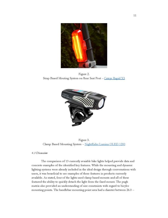
2

Acknowledgements:

       Thank you to Professor Maggie Delano for providing endless guidance
throughout this project and teaching about the importance of user-cent ered design.
Thank you to Jen Moore for aiding in outreach to the Swarthmore biking
community. Thank you to all th e use rs for th e thoughtful survey respons es and
interviews. Thank you to Professors Lynne Molter and Frank Durgin for useful
discussions. And thank you to friends and family for providing support throughout
this project.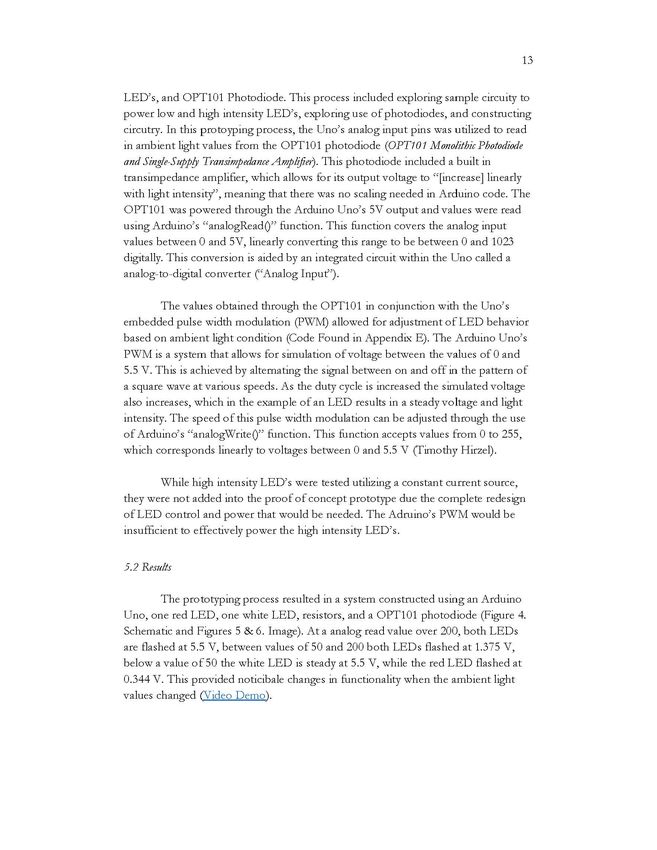
3

Contents

Abstract· ............................................................................................................................................                     1

Acknowledgements:                   .........................................................................................................................             2

1. Introduction: .................................................................................................................................                         5

2. Background: ..................................................................................................................................                          5

     2.1 Bike Lights .. ....... .... ............                 ....... .... ....                                                                                  ..... 5

     2.2 Current Research                                                                                                                                            ..... 6

     2.3 User Centered Design                                                                                                                                   ........... 7

3. Survey /Interviews: .......................................................................................................................                             7

     3.1 Method                                                   ...............             ....................                                                   ..... 7

     3.2 Results.                                                                                                                                                       .. 8

     3.3 Discussion                                                                                                                                                    ... 9

4. Pugh Matrix: ...............................................................................................................................                          10

     4.1 Method.                                                                                                                                                ......... 10

     4.2 Results ...... .                                                                                                                                             ..10

     4.3 Discussion                                                                                                                                                ..... 11

5. Prototyping: ................................................................................................................................                         12

     5.1 Meth od. ...............                                 ...............             ...............                                                   ......... 12

     5.2 Results                                                                                                                                                ·········13

     5.3 Di scuss ion                                                                                                                                              ..... 14

6. Experiment: ................................................................................................................................                          15

     6.1 M eth od              .. ....                                    ... ..                     .... ..                                                    ......... 15

     6.2 Results                                                                                                                                                ......... 16

     6.3 Di scussion ...                                                                                                                                           ..... 16

7. Conclusion: .................................................................................................................................                         17

8. Reflection: ...................................................................................................................................                       18

9. Appendices: .................................................................................................................................                         19

    Appendix A. Pugh Matrix                                       .............. .                                                                              ......... 19

    Appendix B. Survey Questions                                                                                                                                ......... 19

    Appendix C. Int ervie w Qu estions                                                                                                                             ..... 19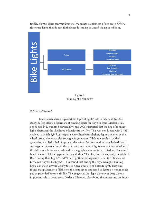
4

    Appendix D. Survey Responses.                                                                                                                  ......... 20

    Appendix E. Arduino Code                                                                                                                       ......... 21

    Appendix F. Daytime Experiment Results                                                                                                         ......... 22

    Appendix G. Nighttime Experiment Results                                                                                                             .. 23

Works Cited: ...................................................................................................................................           24
5

1. Introduction:

         Biking can be a means of transportation for many that is liberating and
relatively accessible, but it can also be quite dangerous. Often drivers fail to see
bikers, leading to catastrophic accidents. According to The Royal Society for the
Pr evention of Accid ents (ROSP A), accidents are most likely to occur betwe en 8:00
to 9:00 am and 3:00 to 6:00 pm on weekdays, suggesting that most accidents occur
while commuting. While these hours may prove to have the most accidents and
about 80% of accidents happen during the day, fatal incidents more often occur at
night (Road Safety Factsheet: CyclingAccidents). ROSPA also reports that 75% of fatal or
serious accidents happen in urban areas, again suggesting a connection with
commuting. While riding to work has seen a decr eas e during th e COVID-19
Pandemic, m any more individuals are out on their bicycl es than in pr evious years
(Adrienne Bernhard). This unique situation serves as an ideal moment to rethink
biker safety and examine th e ways in which lights play a key role in keeping riders
safe. Lights are not the only part of part of the solution, policy and education also
hav e an important role. Engineers have the unique ability to help parse out technical
solutions but also hear from users and communicate their wants and needs with
policy makers. In this project, users' experiences are utilized to identify and specify
key features of the ideal bike light system.

2. Background:

2.1 Bike Lights

         T here are two main types of bik e light s, tho se that afford th e rid er to see and
those that afford the rider to be seen (Figure 1.). Both sets of lights usually afford the
us er to tum th em on and off, charge th em, and adjust the light output. Lights to see
also typically afford the user to mount them on the front of a bicycle, see what is
ahead of a rider, and at times be seen by drivers. These lights tend to have high
int ensity outputs, thus at times this affordance of b eing seen becomes a dis-
affordance by blinding other indiv iduals on the road. Lights to be seen also typically
afford the user to adjust th e flash pattern and be seen by a driv er. Lights can range in
cost anywhere from $20 to $200+. Th ey also hav e a va riety of light int ensity options,
rangin g from 5 to 1600 + lum ens (See Appe ndi x A). Lum ens are th e SI unit of
lumin ous flux or " the measure of the percieved pow er of light'' (Choudhury). A light
out p ut of 5 lumens ma y b e su fficient on a light to b e seen if us ed durin g the night
but is insufficient to be utilized durin g the day. A light output of 1600 lumens is
more than en ough to be utilize d as a light to see but would be blinding to oncoming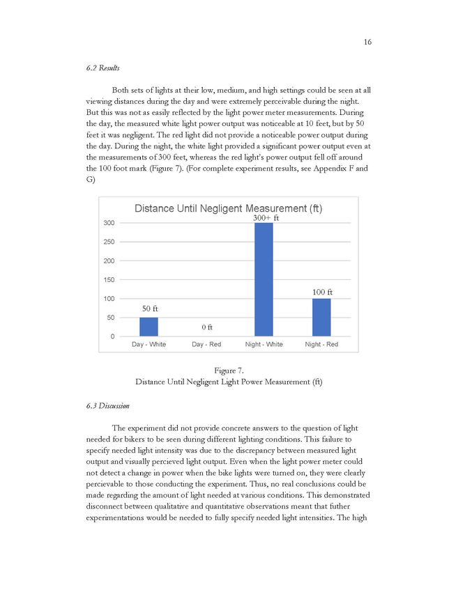
6

traffic. Bicycle lights can vary immensely and have a plethora of use cases. Often,
riders use lights that do not fit their needs leading to unsafe riding conditions.

                                                                       Features

        {
                                                                    -High Intensity
                             To See
                                                                       -Steady
                                                                   -Front Mounted

                                                                       Features
                                                                    -Low Intensity
                           To Be Seen
                                                                       -Flashing
                                                               -Front and Rear Mounted

                                       Figure 1.
                                Bike Light Breakdown

2.2 CurrentResearch

         Some studies have explored the topic of lights' role in biker safety. One
study, Safety effects of permanent running lights for bicycles from Madsen et al.,
conducted in Denmark between 2004 and 2005 suggested that the use of running
lights decreas ed th e likelihood of accid ents by 19%. This was conducted with 3,845
cyclists, in which 1,845 participants were fitted with flashing lights powered as the
wheel turned due to an electrom agnetic generator. While this study provided
grounding that lights help impro ve rider safety, Madsen et al. acknowledged short
comings in the work due to the fact that placement of lights was not examined and
the difference between steady and flashing lights was not tested. Darlene Edewaard
filled in some of these gaps with their studies, " The Daytime Conspicutiy Benefits of
Rear-Facing Bike Lights" and "The Nighttime Conspicuity Benefits of Static and
Dynamic Bicycle Taillights". They found that during th e day and night, flashing
lights enhanced drivers' ability to see riders over use of a steady light. The y also
found that placement of lights on the seatpost as oppossed to lights on non mo v ing
pedals provided better visibility. This suggestes that light placement does play an
important role in being seen. Darlene Edewaard also found that increasing luminous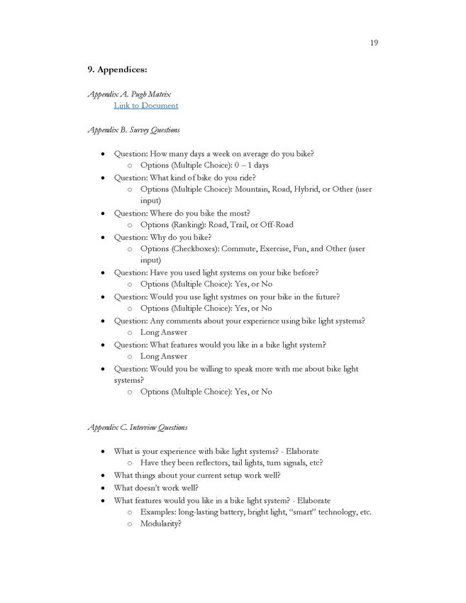
7

intensity of the lights increased visibility of riders; however, they did not suggest
concrete light intensity values that provided the best chances of being seen.

2.3 User Centered Deswz

        While these studies provided important grounding for the project, they did
not examine suggestions that riders might have about the systems they were using or
thought would work well. This is a shortcoming that this project aims to address.
The voices of users are invaluable in design. Often, designers of all types of products
believe that they posses technical understanding     that gives them a better persepective
than users. U sually this is not the case and this short-sightedness   keeps many ideas
from even being brought up in the design process. Not only does exculsion of ideas
lead to less innovation, but it also can put users in unsafe situations. Many riders
have had accid ents and have tried lots oflighting    combinations in the hopes of
keeping themselves safe. This collective knowledge is more extensive than what one
rider could learn and should be utilized to thoughtfully design bik e light systems.

3. Survey /Interviews:

3.1 Method

        Bikers have a wealth of knowledge regarding the performance         of products
currently on the market and many individuals take different approaches to
maintaining their safety while on the road. To utilize that information, a survey was
sent out to members of the Swarthmore biking community through the help of Jen
Moore and to the members of the C hevy Chase Town Listserv. This survey
contained questions regarding users frequency of biking, type of bike, locations of
biking, reasons for biking, and expe rience with bike light systems. (For a full
description of survey questions, see Appendix B) The survey also collected interest
from individuals about being interviewed about the topic of bike lights.

        The individuals who agreed to talk more were interviewed for 30 to 60
minutes and were asked futher questions about their experience with bike light
systems. Th e int erviews were start ed with an introduction   to th e proj ect and goals of
user-center ed design to demonstrat e to the users the va lue of their opinion and
achieve transparency within the project. The questions were intentionally openended
to allow for interviewees to drive the direction of conversation and give a more
wholistic view of lights' role in biker safety. Key questions included: What is your
experience with bike light systems, What features would you like in a bike light
system, Are there things missing from your current system, and How would a bike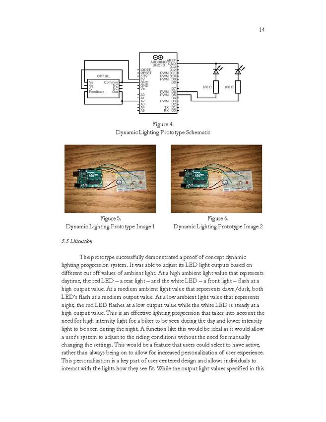
8

light system impact your riding experience? (For a full description of Interview
questions, see Appendix C) Suggestions from users regarding project direction were
also collected to allow for a dynamic project that would change to meet the needs of
users.

3.2 Results

        31 survey responses were gathered and 14 interviews were conducted. The
users on average biked 3.1 days per week and roughly 58% used road bikes. With
regards to bike light systems, 87% had utilized lights on their bikes and 100% of
users expressed interest in using lights in the future. U sers had a wide range of
reasons for biking, but 45% responded that they used biking for commuting, 77%
said they used biking for exercise, and 71% responded that they used biking for fun.
Users also noted that they primarily bik e on roads, with some individuals riding on
bike trails, and even fewer riding "off-road". (See full data in Appendix D)

        In the interviews users provided information regarding four key topic areas:
lights being too bright, lights being seen from the sides of bikers, mounting points,
and desired features. When discussing lights being too bright, users noted being
blinded by oncoming bikers when on trails or roads. Users suggested that this may
be due to individuals pointing lights to high or using lights that were too powerful
for the given lighting conditions. This note that lights may be pointed too high
carri ed into conversations about light mounts. Us ers not ed that oft entim es this is a
key piece of the light system that goes overlooked. Mounts often times are cheap and
do not keep a light in place, they allow the light to move around becoming either
impercievable or blinding to other individuals. Many users noted the benefit of
having multiple mounts but one light, this allows for a rider to attatch mounts to
various bicycle s and easily change th e light b etween them. This allows for a
combination of the benefits of easily removable mounts and fixed mounts.
Additionally, riders mentioned use of mounting points beyond the seatpost and
handlebars, such as on bags, pedals, ankles, and helmets. Users noted that these
placements all increased the likelihood that another individual would be able to see
them and would sometimes increase the ability to see. Some of the desired additional
features that users mentioned focused on battery, including USB charging, alternative
methods of charging, and notification of remaining battery life. Users also discussed
the ability to adjust output intensity and modes in a intuitive manner.
9
3.3 Discussion
The survey and interviews provided helpful grounding for different elements
of riders' bike light experiences. Through this data collection process, it was
understood that riding during the day and night present different issues. During the
day, riders just need light to be seen. During the night, riders need light to be seen
and to see. Different riding environments such as an unlit trail or a city road with
street lights also play into the needs of a user at any given time. The users also came
up with ideas that were out of the box and thought wholistically about their
experience as riders, this was something that greatly aided the process of discerning
what features were considered ideal. With regards to being seen, users explained that
it is much harder to find good rear lights. Often times lights do not have the features
that they desire and they ultimately feel unsure of how viewable they are. Users also
discussed the notion of target audience, which led to a focusing of the project
towards commuters. Whil e users provid ed lots of information regarding ideal
features within bikelights, they noted that the physical lights are only part of a
solution for biker safety. Education for drivers is needed for keeping bikers safe and
education is needed for riders about using bike lights effectively.
Through these inverviews and surverys four main featur e areas were
identified as being important to address in this project. The first was the intensity of
light; to mak e an effective bike light, it must eith er b e see n wh en it is suppos ed to b e
or light up a path effectively for a rider These both hinge on the amount of light
output. E ffective light intensities w ere not identified through conversations with
users. The second was the transition between different riding situations, this is
generally reliant upon the ambient light conditions of the environment. Through
conv ersations with users, an approach that adjusts light output given th e ambi ent
light condititions was devised. During the day, this planned system would have both
front and rear lights function as high powered lights to be seen, as the ambient light
decreased during dawn or dusk, both lights would transition to being low powered
lights to be seen, and at night the front light would illuminate fully as a steady light to
see, while the back light would dim to an even lower intensity light to be seen. The
third was battery life; while effective battery life was not identified, many users
expressed a need for their lights to function throughout a work week. Fourth was
mounting system, which most users prefered to be a fixed mount with the ability to
quickly detach the light. The remaining parts of the project look to fully specify the
amount of light needed and battery life elements of the desired features.10
4. Pugh Matrix:
4.1 Method
After conducting the surveys and interviews, a thorough comparison of bike
lights currently avaiable for purchase was conducted to provide background
information for the design process. These specific lights were selected through
recommendations by interviewees and ranked lists of bike lights found online. The
technical specifications for all o f the lights were found through company w ebsites
and report ed data sh eets. Th ese sp ecifications wer e describ ed in th e format of a
Pugh Matrix and included: use cases, batt ery life, light output, mounting system,
output modes, batt ery indication system, dynamic lighting system, and pric e. Th ese
specific details were examined to match the four feature areas of interest designated
through the user surv eys and interviews.
4.2 Results
The pugh matrix (Appenix A) of bike lights resulted in a comparis on of 13
lights. Nine of these systems function ed as rear lights, while six of them function ed
as front lights. The lights rang e in pric e from $20 to $200 and had outputs from 5 to
1600 lumens. The reported b attery life on the lights ranged from 53 hours at a 5
lumen flashing output (Leyzne) to 1.3 hours at a 1600 lumen steady o utput
(BlackBum). Five of th e lights had dynami c lighting functionality meanin g that v ia
accelerom eter, photosensor, or GPS, the systems w ere able to chang e th eir light
output to fit the given situation. Th ese dynamic adjustments includ ed: increasing
light output when braking, increasing light output when a car is approachin g, and
incr easing light output when appro aching intersections. Of the 13 lights, 10 included
batt ery level no tification systems, th ese ranged from a light that blinks when th e
b attery is low to an LCD display that indicates the remaining time at a give n setting.
With regards to mounting, nine of the lights featured a strap b ased system (Figures
2.), w hile the remai n ing four ut ilized clamp bas ed systems (Figure 3.). Five of th ese
systems were purchased for additi onal testing and examination: Leynze, Blitzu,
BOHSRL , Night Rider Swift, an d NightR ider Sola s.11
Figure 2.
Strap Based Mouting System on Rear Seat Post - Cateye Rapid X3
Figure 3.
Clamp Based Mounting System - N ightRider Lumina OLED 1200
4.3 Discussion
T he comparison of 13 currently avaiable bike lights helped provide data and
concrete examples of the identified key features. While the mounting and dynamic
lighting systems were already included in the ideal design through conversations with
us ers, it was beneficial to see exam ples of these features in products curr en tly
available. As stated, four of the lights used clamp based mounts and all of these
featu red th e ability to quickly detach th e light from th e fixed mount. T h e pugh
matrix also provided an understanding of size constraints with regard to bicylce
mounting points. The handl ebar mounting point area had a diamt er b etween 26.0 -12
31.8 mm, while the seat post mounting area was between 27 .2 - 31.6 mm (Sheldon
Brown). Five of the lights also featured dynamic lighting systems. Some of these
were similar to the ones devised through user conversations, but others utilized more
complex systems such as GPS for seemingly little added benefit. Additionally, four of
the five lights featuring dynamic adjustment were over $100, suggesting that this is
considered an expensive feature. This made little sense as it seemed that a system
controled with ambient light detection would not be particularly expensiv e to
construct and would accomplish all of the same goals as the pricier lights.
The pugh matrix provided a better understanding of expected battery
performance out of bike light systems. Many of the lights claim ed to have battery
lives that were longer than 15 hours but this was often at a light intensity level that
would be insufficient for use during the day. The typical battery life at a useful
insenity was between 4 - 7 hours. A value of 5 hours of useful insenity was
determined to be sufficient through these discovered values and users requests for
lights to function for a whole commuting week. This va lue was confirmed to be
suffici ent wh en e stimating th e averag e on e way bike commut e to be 3 mil es in a
metropolian area at a speed of 10 MPH over the course of a week (Buehler).
miles trips minutes
3 -- * 2 -- * 6---- * 5 days = 180 minutes = 3 hours
trip day mile
While the pugh matrix did provide a better understanding of the range of
avaiable light int ensities, it did not help to det ermine what was conside red sufficient
light under various conditions. Many of the lights had output modes that would
undeiperform during the day tim e or blind dri ve rs during th e night time. This
qu estion needed to b e explor ed in mor e d etail.
T he pugh matrix ultimat ely helped to disc ern acceptabl e batt ery life tim es,
provide examples of mounting systems and dyanmic light adjustment, and give more
understanding of products currently available. This was important to provide context
for systems that riders were actively utilizing to show the gaps that a user-centered
design bike light could fill. However, this exploration fell short to determine how
much light output was needed given various conditions.
5. Prototyping:
5 .1 Method
Aft er conducting the comparison of curr ently available bike lights, a physical
prototyp e was construct ed through th e us e of an Arduino Uno, resistors, low pow er13
LED's, and OPT101 Photodiode. This process included exploring sample circuity to
power low and high intensity LED's, exploring use of photodiodes, and constructing
circutry. In this protoyping process, the Uno's analog input pins was utilized to read
in ambient light values from the OPTlOl photodiode (OPT101 MonolithicPhotodiode
and Single-Supp!JTransimpedance Amplifier). This photodiode included a built in
transimpedance amplifier, which allows for its output voltage to "[increase] linearly
with light intensity", meaning that there was no scaling needed in Arduino code. The
OPTlOl was powered through the Arduino Uno's 5V output and values were read
using Arduino's "analogRead0" function. This function covers the analog input
values between 0 and 5V, linearly converting this range to be between 0 and 1023
digitally. This conversion is aided by an integrated circuit within the Uno called a
analog-to-digital converter ("Analog Input'').
The values obtained through the OPT101 in conjunction with the Uno's
embedded pulse width modulation (PWM) allowed for adjustment of LED behavior
based on ambient light condition (Code Found in Appendix E). The Arduino Uno's
PWM is a system that allows for simulation of voltag e b etween th e values of 0 and
5.5 V. This is achieved by alternating the signal between on and off in the pattern of
a square wave at various speeds. As the duty cycle is increased the simulated voltage
also increases, which in the example of an LED results in a steady voltage and light
intensity. The speed of this pulse width modulation can be adjusted through the use
of Arduino's "analogWrite0" function. This function accepts values from Oto 255,
which corresponds linearly to voltages between 0 and 5.5 V (Timothy Hirzel).
While high intensity LED's were tested utilizing a constant current source,
they were not added into the proof of concept prototype due the complete red esign
of LED control and power that would be needed. The Adruino's PWM would be
insufficient to effectively power the high intensity LED's.
5.2 Results
The prototyping process resulted in a system constructed using an Arduino
Uno, one red LED, one white LED, resistors, and a OPT101 photodiode (Figure 4.
Schematic and Figures 5 & 6. Image). At a analog read value over 200, both LEDs
are flashed at 5.5 V, betwe en values of 50 and 200 both LEDs flash ed at 1.375 V,
below a value of 50 the white LED is steady at 5.5 V, while the red LED flashed at
0.344 V. This provided noticibale changes in functionality when the ambient light
values changed (Video Demo ).14
E0
ARDUINOAREF
UNO r3 GD~~
IOREF D12
RESET PWM Dll
OPT101 3.3V PWM D10
sv PWM D9
Vs Common GND D8
·In NC GND
·V NC Vin D7 1000
Feedback Out PWM D6
AO PWM DS
Al D4
A2 PWM D3
A3 D2
A4 TX D1
AS RX DO
Figure 4.
Dynamic Lighting Prototype Schematic
Figure 5. Figure 6.
Dynamic Lighting Prototype Image 1 Dynamic Lighting Prototype Image 2
5.3 Discussion
The prototype successfully demonstrated a proof of concept dynamic
lighting progression system. It was able to adjust its LED light outputs based on
different cut off values of ambient light. At a high ambient light value that rep res en ts
daytime, the red LED - a rear light- and the white LED - a front light- flash at a
high output value. At a medium ambient light value that represents dawn/dusk, both
LED's flash at a medium output value. At a low ambient light value that represents
night, the red LED flashes at a low output value while the white LED is steady at a
high output value. This is an effective lighting progression that takes into account the
need for high intensity light for a biker to be seen during the day and lower in tensity
light to be seen during the night A function like this would be ideal as it would allow
a users system to adjust to the riding conditions without the need for manually
changing the settings. This would be a feature that users could select to have active,
rather than always being on to allow for increased personalization of user experience.
This personalization is a key part of user centered design and allows individuals to
interact with the lights how they see fit While the output light values specified in this15
prototype were not sufficient to be utilized as a bike light, they effectively
demonstrated that this desired system would be possible to implement. The cut off
ambient light values used in the prototype were not specified to real ambient light
conditions, but instead were picked for demonstration's sake. These could easily be
adjusted in the Arduino to pick more suitable ambient light values if desired.
6. Experiment:
6.1 Method
With the only remaining featur e to specify b eing the int ensity of light n eed ed
under different conditions, conversations with Swarthmore professors were
arranged. Lynne Molter, an optics professor in the engineering department,
explained that the question of light intensity is more complicated than initially
imagined. She explained that v iewing distance depends on factors such as light color,
type oflight, lenses used to focus the light, and other environmental factors. Frank
Durgin, a professor in the Physchology department, explained that humans are
notriously bad at perceiving distance and size, key components in a bike light's
success, especially at night This lead to new thinking and a greater focus about the
differenc e in conditions of daytime versus night time.
Thus, a practical experiment was created to measure what amount of light is
necessary in different lighting conditions. A white light, NightRider Swift 500, and
red light, Leyzn e Strip Drive Pro Rear, were utili zed in the expe riment as light
sources. The white light had three output modes, desc ribed as 100, 225, and 500
Lumens. The red light had 11 output modes, but only three were used, 5, 25, and 50
lumens. (See more details about lights in Pugh Matrix, Appendix A). The lights were
tested during the day and night on the track located at Swarthmore College. A
Coherent Fieldmaster Power Meter coupled with a Coherent LM-2 High-Sensitivity
Optical Sen sor were utiliz ed to m easur e light output pow er. Th e LM -2 Opt ical
Sensor is a photodiode that "[converts] incident photons into current, providing a
highly sensitiv e power sensor'' (H igh-SensitivityOpticalSensors).The light power output
of both sets of lights were measured at 10, 20, 30, 40, 50, 100, 200, and 300 feet At
eac h distance, three measurements of changes in light ouput power were measured
and averaged. Th ese m easurem ents were tak en with th e light shining dir ectly at th e
LM-2 Opitcal Sensor and coupled with manual adjustment of light output angle, by
tilting th e light up, down, and side to side, to see maximum results. Thes e valu es
were recorded in microwatts of power.16
6.2 &suits
Both sets of lights at their low, medium, and high settings could be seen at all
viewing distances during the day and were extremely perceivable during the night
But this was not as easily reflected by the light power meter measurements. During
the day, the measured white light power output was noticeable at 10 feet, but by 50
feet it was negligent. The red light did not provide a noticeable power output during
the day. During the night, the white light provided a significant power output even at
the measurements of300 feet, whereas the red light's power output fell off around
the 100 foot mark (Figure 7). (For complete experiment results, see Appendix F and
G)
DistanceUntilNegligentMeasurement(ft)
300+ ft
300
250
200
150
100 ft
100
50 ft
50
0 ft
0
Day- White Day- Red Night - White Night- Red
Figure 7.
Distance Until Negligent Light Power Measurement (fi:)
6.3 Discussion
The experiment did not provide concrete answers to the question of light
need ed for bik ers to be seen during diff erent lighting conditions. This failure to
specify needed light intensity was due to the discrepancy between measured light
output and visually perci eved light output. Ev en when the light pow er m eter could
not detect a change in power when the bike lights were turned on, they were clearly
percievable to those conducting the experiment. Thus, no real conclusions could be
made regarding the amount of light needed at various conditions. This demonstrated
disconnect between qualitative and quantitative observations meant that futher
experimentations would be needed to fully specify needed light intensities. The high17
ambient light of the surroundings during the day was likey why the measured output
from the power meter did not reflect significant changes. The more pronounced
difference in values during the nighttime was likely due to reduced ambient light
conditions. While the experiment did not result in specific target values of light
output for the ideal design, it did confirm the need for higher light outputs during
the day, thus supporting the dynamic light progression previously designed.
7. Conclusion:
This proj ect did not result in a fully develop ed bik e light prototyp e that
included all of the features identified as important as initially intended; however, it
did effectively take a us er centered design approach towards exploration oflights'
role in biker safety. To start the project, interviews with users were conducted
resulting in the selection of four topic areas of focus: battery life, dyn amic lighting
progression, intensity oflight needed during different conditions, and mounting
system. Through the interviews, a dynamic lighting progression was outlin ed and
ideal mounting system was determined. Further research was conducted in the form
of a pugh matrix, comparing various lights currently avaiabl e. This helped to
determine ideal battery life time and solidified ideas regarding the approach to
dynamic lighting. A physical prototype was constructed through the use of an
Arduino Uno to test said dynamic lighting system, which functi o ned successfully.
Finally, a practical experiment was conducted with the hopes of finalizing ideal light
intensities at various ambient light conditions, but this experiment did not
accomplish its goals. The exp erimentation led to the conclusion that mor e int ensiv e
and interdisciplinary m ethods would need to be undertaken to answer the question
of sufficient light intensity values. Ultimately, the project resulted in the
determination that the ideal light system would utilize a fixed mount, have 5+ hours
of useful intensity lighting, and a dynamic lighting system that would adjust the
light's intensity and functionality based on the given environmental conditions. While
these specifications of the ideal bike light are beneficial, th e bigg est take away was
th e import anc e o f us er-cent ere d design. O ften, us ers' voic es are left out of th e
process of design, leaving valuable insight unused. When this information is not
explo red in th e cas e of bik e lights, rid ers en d up using lights that don't fit th eir needs,
underperform and often times are far too expensive. Inadequate bike lights cause
riders to get hit by vehicles. Users should be listened to and their ideas ought to be
built upon to help identify probl ems and creat e solutions.18
8. Reflection:
Through this project, I was able to explore an activity that I love, biking, in
more detail and think in a new way about biker safety. Staying safe while riding has
always been important to me and thinking about new ways to keep myself and other
safe was engaging and meaningful. I was also able to put the skills of user-centered
design into practice. Through classes and other projects I had explored this topic
within design, but putting it to the test in the context of a senior comprehensive
project was quite rewarding. I was able to see the passion that so many users had
when it came to biking and keeping themselves safe. I heard about experiences and
accidents that would have normally only been represented as statistics. And I learned
that great ideas can come out of talking with so many people. We should not
perform engineering in a bubble, disconnected from those that our products or
solutions serve. Instead, we need to talk with these people and pull on the resources
around us. Engineering has the opportunity to be multidisciplinary and I learned that
we should embrace that.19
9. Appendices:
Appendix A. PughMatrix
Link to Do cum en t
Appendix B. SurvryQuestions
• Question: How many days a week on average do you bike?
o Options (l'vfultipleChoice): 0 - 1 days
• Question: What kind of bike do you ride?
o Options (l'vfultipleChoice): Mountain, Road, Hybrid, or Other (user
input)
• Question: Where do you bike the most?
o Options (Ranking): Road, Trail, or Off-Road
• Question: Why do you bike?
o Options (Checkboxes): Commute, Exercise, Fun, and Other (user
input)
• Question: Have you used light systems on your bike before?
o Options (l'vfultipleChoice): Yes, or No
• Question: Would you use light systmes on your bike in the future?
o Options (l'vfultipleChoice): Yes, or No
• Qu estion: Any comm ents about your experience using bik e light systems?
o Long Answer
• Question: What features would you like in a bike light system?
o Long Answer
• Question: Would you be willing to speak more with me about bike light
systems?
o Options (l'vfultipleChoice): Yes, or No
Appendix C. InterviewQuestions
• What is your experience with bike light systems? - Elaborate
o Hav e th ey been reflectors, tail lights, tum signals, etc?
• What things about your curr ent setup wo rk well?
• What do esn't work well?
• What features would you like in a bik e light system? - E laborat e
o Examples: long-lasting battery, bright light, "smart'' technology, etc.
o Modularity?20
• Are there things missing from your current system?
• What do you think about having brake light capabilities or turn signals
incorporated into the system?
• How would a bike light system impact your riding experience?
• Would you use a bike light system in the futur e?
o Why or why not?
• Are you concerned about biker safety and what role do you think light
systems play in safety?
• What is the price range you would be willing to pay for a system?
• What else are you doing to make yourself more visible when you ride?
• What suggestions do you have for me as I go through this project?
Appendix D. SurvryResponses
Link to Docum ent ~ Not e: emails and som e answ ers remov ed for anonymity21
App endix E. Arduino Code
int voltage;
bool night;
int LED_PIN_l = 6;
int LED_PIN_2 = 5;
int delay_time = 1000;
void setup(){
pinMode(6, OUTPUT); //LED 1
pinMode(5, OUTPUT); //LED2
pinMode (A2, INPUT); //DETECTOR
Serial.begin(9600); // opens seria I port, sets data rate to 9600 bps
Seria l.println("Hello");
}
void loop(){
voltage= analogRead(A2);
// float spectral Response= map(voltage,0,1023,400,1100) ;
Serial.print("Voltage: ");
Serial.print(voltage);
Serial.println();
if (voltage< 50){
analogWrite(LED_PIN_l,255);
analogWrite(LED _PIN_2, 255/16);
night = true;
}
else if (voltage < 200){
analogWrite(LED_PIN_l,255/4);
analogWrite(LED_PIN_2,255/4) ;
night= false;
}
else{
analogWrite(LED_PIN_l,255) ;
analogWrite(LED_PIN_2,255);
night = false;
}
if ( night){
delay(delay_time) ;
analogWrite(LED_PIN_2,0);
}else{
delay(delay_time);
analogWrite(LED _PIN_l,0) ;
analogWrite(LED_PIN_2,0);
}
delay(delay_time);
}22
Appendix F. Daytime Experiment Results
I:,.
Light Light Light
Ambient Distance Source !:,.Light Ambient Distance Source Power
Conditions Color (FT) Level PoweruW Conditions Color (FT) Level uW
Day White 10 Low 13 Day Red 10 Low 0
Day White 10 Med 19 Day Red 10 Med 0
Day White 10 High 35.66666667 Day Red 10 High 0
Day White 20 Low 3.666666667 Day Red 20 Low 0
Day White 20 Med 5.666666667 Day Red 20 Med 0
Day White 20 High 9.333333333 Day Red 20 High 0
Day White 30 Low 1 Day Red 30 Low 0
Day White 30 Med 2.666666667 Day Red 30 Med 0
Day White 30 High 5 Day Red 30 High 0
Day White 40 Low 0 Day Red 40 Low 0
Day White 40 Med 0 Day Red 40 Med 0
Day White 40 Hi gh 1.666666667 Day Red 40 High 0
Day White 50 Low 0 Day Red 50 Low 0
Day White 50 Med 0 Day Red 50 Med 0
Day White 50 High 1 Day Red 50 High 0
Day White 100 Low 0 Day Red 100 Low 0
Day White 100 Med 0 Day Red 100 Med 0
Day White 100 High 0 Da y Red 100 High 0
Day White 200 Low 0 Day Red 200 Low 0
Day White 200 Med 0 Day Red 200 Med 0
Day White 200 High 0 Day Red 200 High 0
Day White 300 Low 0 Da y Red 300 Low 0
Day White 300 Med 0 Day Red 300 Med 0
Day White 300 H igh 0 Day Red 300 High 023
Appendix G. Nighttime Experiment Results
Light l:::..Light Light l:::..Light
Ambient Distance Source Power Ambient Distance Source Power
Conditions Color (FT) Level uW Conditions Color (FT) Level uW
Night White 10 Low 9.36 Night Red 100 Low 0.001
Night White 10 Med 15.5 Night Red 200 Med 0.001
Night White 10 High 31.2 Night Red 300 High 0.005
Night White 20 Low 2.08
i
Night White 20 Med 3
Night White 20 High 4.86
N ight White 30 Low 0.675
Night White 30 Med 1.43
N ight White 30 High r 2.1
Night White 40 Low 0.346
N ight White 40 Med 1.11
N ight White 40 High 2.13
Night White SO Low 0.372
I
Night White SO Med 072
N ight White SO High 1.17
Night White 100 Low 0.87
i
N ight White 100 Med 0.181
Night White 100 High 0.32
Night Whit e 200 Low 0.25
Night White 200 Med 0.46
i
Night White 200 High 0.9
Night White 300 Low 0.14
Night White 300 M ed 0.24
Night White 300 High 04524
Works Cited:
Choudhury, Asim Kumar Roy. "1 - Characteristics of Light Sources. " Principlesif Colour
and AppearanceMeasurement,edited by Asim Kumar Roy Choudhury, Woodhead
Publishing, 2014, pp. 1-52. ScienceDirect,doi: 10.1533/9780857099242. 1.
Adrienne Bernhard. "Th e Gr eat Bicycle Boom of 2020." BBC,
https://www.bbc.com/future /bespoke /made-on-earth/ the-great-bicycle-boom-of-
2020.htm l. Accessed 11 May 2021.
"Analog Input." Arduino, 28 July 2015,
https://www.arduino.cc/en /Tu torial/BuiltlnExamples /Analoglnpu t .
Brown, Sheldon. Handlebar and Stem Dimension Crib Sheet.
https: / /www.sheldonbrown.com/cribsheet-handlebars.htm l. Accessed 16 May 2021.
---. SeatpostSize Database. htms: / /www.sheldonbrown.com / seamost-sizes.htm l. Accessed
9 Mar. 2021.
Buehler, Ralph. "D eterm inants of Bicycle Commuting in the Washington, DC Region :
The Role of Bicycle Parking, Cyclist Showers, and Free Car Parking at Work."
TransportationResearchPart D: Transportand Environment,vo l. 17, no. 7, Oct. 2012, pp.
525-31. DOI.oi;g(Crossrej),doi: 10.1016/j.trd.2012.06.003 .
Cycling-Accidents-Factsheet.Pdj.
https://www.rospa.com/rospaweb /docs/advice-
services /road-safety / cyclists/ cycling-accidents-factsheet.pdf. Accessed 2 Mar. 2021.
Edewaard, Darlene Elise. The Dqytime ConspicuityBenefitsefR ear-Facing Bike Lights. Clemson,
Aug . 2020, https: / / tiger:prints.clemson.edu / all dissertations /2682 .
---. The Nighttime ConspicuityBenefitsefStatic and DynamicBirycleTaillights. Clems on, 2017.
Zotero, https: / / tiger:prints.clem son.edu / all theses / 2620 .25
High-SensitiviryOpticalSensors.Coherent,
https: / /www.coherent.com/assets/pdf/COHR OP-2 LM-
2 Optica!Sensors DS 1119 2.pdf.
Jack -kay. "OPT101 SENSOR AND LEDs INACCURATE READING." AnluinoFomm,
16 May 2016, https: / /forum.arduino.cc !ti optlOl-sensor-and-leds-inaccurate-
reading/386165 .
Madsen, J.C.0., et al. " Safety Effects of Permanent Running Lights for Bicycles: A
Controlled Experiment." AccidentAna!Jsis & Prevention,vol. 50,Jan. 2013, pp. 820-
29. DOI.or;g(Crossref),doi: 10.1016 /j.aap.2012.07.006 .
0PT101 OPT101 MonolithicPhotodiodeand S ingle-Supp!JT ransimpedance
Amplifi er. Texas
Instruments , June 2015, https: / /www.ti.com/lit / ds/symlink / opt101.pdf.
Road Safe!}Factsheet: Qycling Accidents. The Royal Society for the Prevention of Accidents,
No v. 2017, https: // www.rospa.com/rospaw eb / docs / advice-services / road-
safety/ cyclists /cycling-accidents-factsheet.pdf.
T imothy H irzel. "PWM." Ar duino, 5 Feb. 2018,
https: / /www.arduino.cc/en / Tutorial/Foundations / PWM .You can also read