User Manual - Multi-function Flue Gas Analyzer - Crowcon
←
→
Page content transcription
If your browser does not render page correctly, please read the page content below

Multi-function Flue Gas Analyzer

                      Sprint Pro 3
                    5430910000J18

                   Your company name
                  Your Company Phone

            User Manual

M07016
July 2019
Issue 3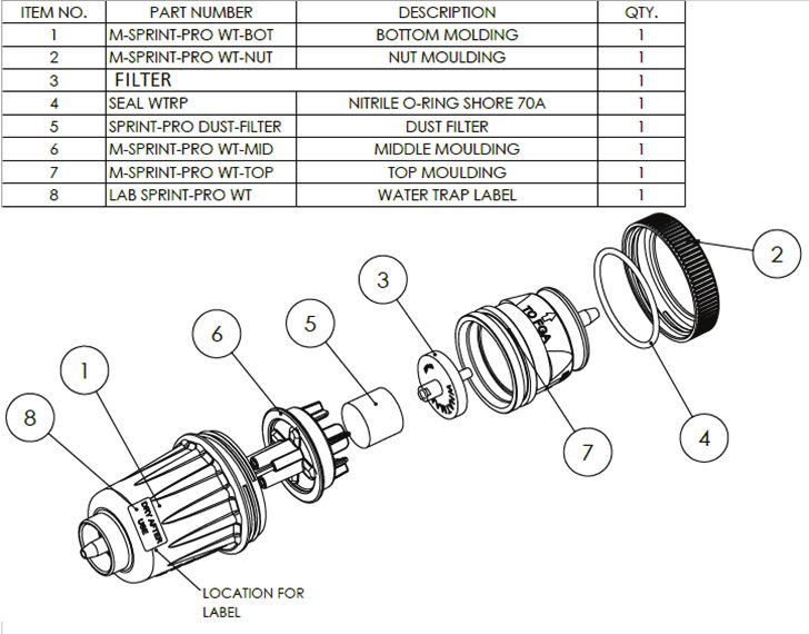
Summary of Screen Icons               Safety and product related information:
                                      •   Read and understand all instructions in the operation sec-
    Select, pick or action
                                          tion of this manual before use.
    Up item or entry                  •   Observe all warnings and instructions marked on Sprint
    Down item or entry                    Pro, or as prompted by the analyzer and within this manual.
                                      •   Sprint Pro must only be operated with the Sprint Pro Flue
    Left field                            Probe assembly and always with the water trap and filters
    Right field                           in place.
                                      •   Connect the Flue Probe Assembly to Sprint Pro before
    Zero pressure
                                          switching on and do not insert probe into flue until after
    Start timed test                      the zeroing process is complete.
                                      •   Sprint Pro water trap must be dried after use and before
    Stop timed test
                                          Sprint Pro Flue Probe Assembly is returned to carry case.
    Restart timed test                •   Before use ensure Sprint Pro is in good repair and do not
                                          use if damaged or if calibration has expired.
    Yes, pass or done
                                      •   Sprint Pro passes the requirements of EN50379-1 and
    No or fail or cancel                  EN50379-3 and has been independently tested by BSI.
    Purge or pump running icon        •   Sprint Pro is designed for use in ambient temperatures in
                                          the range 14°F to 122°F and should not be used outside
    Select temp 1 (flow)
                                          this range.
    (Differential Temperature Test)
    Select temp 2 (return)            •   Sprint Pro contains a re-chargeable Lithium ion battery.
    (Differential Temperature Test)   •   Sprint Pro’s battery must not be charged at temperatures
    Save log                              below 32°F or above 104°F.
                                      •   If Sprint Po is damaged do not use and return to a quali-
    Export report/log to IR Printer
                                          fied service center for repair/replacement.
    Export report/log to Mobile App   •   Service, calibration & repair of Sprint Pro must only be
                                          undertaken by a qualified service center.
    Delete
                                      •   Do not substitute components as this may impair safety
    Edit value                            and invalidate warranty.
    Increase value                    •   Repair of Sprint Pro and gas sensor replacement shall be
                                          carried out by the manufacturer or qualified service center
    Decrease value                        in accordance with the applicable code of practice.
    Descend through character list    •   If this product is not working properly, read the trouble-
    (String edit)
                                          shooting guide or contact the service center.
    Ascend through character list
    (String edit)                     •   Batteries are non-replaceable by the user and must only
                                          be replaced by authorised service centers.
    CO Alarm
                                      •   Sprint Pro battery is rechargeable via a USB-C input con-
                                          nector.
                                      •   Sprint Pro must be charged via a USB charger that meets
                                          the specification as detailed in the user manual.
                                      •   Sprint Pro is not to be used as a permanent fixed detector.
                                      •   Sprint Pro is not designed or tested for continuous use.
                                      •   Sprint Pro is not a safety alarm.
                                      •   Only use probes, leads and accessories supplied by the
                                          manufacture.
           IR Printer Alignment       •   Do not subject the product to cleaning fluids, such as
                                          those containing high concentrations of acetone and
                                          silicone compounds (such as silicone grease).
• Do not immerse in water.
• Do not use silicon grease on the O-rings.
• Fuel options available are: natural gas, LPG, heavy
oil, light oil, kerosene, coal, wood, wood pellet
dry, coke, Biomass and Bagasse.
Additional information:
Sprint Pro is designed to meet the requirements of
EN50379-1 and EN50379-3 and to support the work-
ing practices defined in Standard BS7967.
It is highly recommended that users are fully con-
versant with local regulations when using a flue gas
analyzer for servicing or installing a boiler system.
When performing any CO measurements ensure
the unit is zeroed in clean air. A suitable location
for sampling clean air will be outside of the build-
ing where the boiler system is installed, away from
exhaust vents.
Sprint Pro offers a timed let-by/tightness test.
If the Sprint Pro has not been used for more than
6 months it should be put on charge for at least 4
hours without use. This will allow the oxygen chan-
nel and if present the NO channel, to read correctly.
Failure to do this may cause the oxygen measure-
ment, the NO measurement and any calculations
depending upon them to be incorrect.
Magnets on the reverse of Sprint Pro can be used to
place the Sprint Pro in location on the boiler system
for easy hands-free operation.
Diagnostics and usage data from Sprint Pro is acces-
sible at service and can be viewed at service centers.
We reserve the right to update and enhance the soft-
ware at times of service without prior knowledge.
WARNING: Take care not to place items which may
be sensitive to strong magnetic fields near this mag-
net, e.g. credit cards or magnetic storage devices like
computer hard drives.
FCC compliance
Sprint Pro FCC number: A8TBM78ABCDEFGH
© Copyright Crowcon Detection Instruments Ltd 2019.
All rights are reserved. No part of the document may be
photocopied, reproduced, or translated to another language
without the prior written consent of Crowcon Detection
Instruments Ltd.
Publication number: M07016
Second edition: May 2019
NOTE:
This product uses the FreeRTOS.org real time kernel available from http://www.FreeRTOS.org
The FreeRTOS source code is licensed by the GNU General Public License (GPL) with an exception.
The full text of the GPL is available here: http://www.freertos.org/license.txt.
The text of the exception is available on FreeRTOS official website: http://www.FreeRTOS.org - License and Warranty PageContents
Sprint Pro Multi-function Flue Gas Analyzer................................... 2
Unpacking.................................................................................................... 2
I. Sprint Pro Orientation................................................................. 3
Overview...................................................................................................... 3
Probe connections........................................................................................ 4
Switch on and using the Menu..................................................................... 4
Switch off..................................................................................................... 4
Charging battery........................................................................................... 5
Pump............................................................................................................ 8
Keypad overview........................................................................................... 8
Menu structure............................................................................................. 9
II. Set Up & Menu Configuration Options...................................... 10
Fuel options................................................................................................ 10
Units of measurement................................................................................. 10
Analyzer settings......................................................................................... 10
III. Performing tests...................................................................... 14
Zeroing process........................................................................................... 14
1. Flue gas analysis...................................................................................... 15
2.Differential temperature test........................................................................... 16
3.Room Safety Test........................................................................................... 19
4. Appliance sweep test................................................................................ 20
IV. Logging.................................................................................. 24
V. Test Report/Log exporting........................................................ 25
VI. Maintenance and Calibration.................................................. 26
VII. Sprint Pro Specification.......................................................... 28
VIII. Troubleshooting guide........................................................... 31
Appendix I: Room Safety Test....................................................... 33
Warranty..................................................................................... 37
Sprint Pro Warranty Limitations......................................................... 38Unpacking Sprint Pro
Sprint Pro
Multi-function Flue Gas Analyzer
Thank you for purchasing the Sprint Pro Multi-function Flue Gas Analyzer.
Sprint Pro will give you years of unparalleled service and reliability if looked
after correctly.
There are three versions covered in this manual as follows:
Please read the instructions carefully before use. Keep the manual for
future reference.
Unpacking
Important: Please fully charger Sprint Pro before use.
Remove the Sprint Pro from the packaging. The Sprint Pro accessories will
be located in the carry case. Check the contents are complete, you should
have:
• Sprint Pro Analyzer.
• USB charger and USB lead.
• Flue probe assembly, including water trap and filters.
2Sprint Pro Sprint Pro Orientation
I. Sprint Pro Orientation
Overview
Display
Showing start-up
splash screen
Sprint Pro 3
5430910000J18
Battery icon
Soft keys Three bars show
Use these unmarked buttons Your company name complete charge
Your Company Phone
to make selections from the
menu, start and stop tests, Purge icon
print and store results. Rotating icon shows
See section Operation for more pump is purging
details
ON/OFF/ENTER key
ESCAPE key
Press and hold button for two
Use this button to quit
seconds to switch on and switch
tests and step back
off Sprint Pro. Use this key to
through menus.
finish edits, save changes and
view next page of multiple
paged screens.
IR window
USB connector Printer output
For charging and
communications to PC
Exhaust exit
Warning: do not
inhale exit gas exhaust
or block exit
Thermocouple
sockets
K-type connectors
Flue sample inlet
3Sprint Pro Orientation Sprint Pro
Probe connections
Flue gas analysis
Connect the flue probe to the flue sample inlet and the thermocouple to either
K-connector.
To measure flue draught pressure connect pressure tube to (-) pressure inlet.
Differential temperature test
Connect one (or two) thermocouple probes to the K-type connectors.
When using one probe, Sprint Pro will display a soft key option to switch
between T1 and T2 snapshot measuring points.
Note: When using (a) two thermocouples on metal pipes, or (b) any thermocouples
whilst the Sprint is on charge - electrically isolated thermocouples should be used.
Alternatively, cover the thermocouple contacts with plumbers tape to electrically isolate
the thermocouple contacts from the pipes.
Switch on and using the Menu
Press and hold the ON/OFF/ENTER key for two seconds.
Sprint Pro will emit a few rising beeps, display the Main Menu
14:44:54 02-Nov-2018
splash screen and then enter the Main Menu. Cal due 02 Nov 2019
Use the soft keys to scroll, select and edit menu items Test Menu
Fuel Options
(see icon list – inside front cover). Press accept to Units of Measurement
make a change or the ESC key to cancel. Press the ESC Zero Gas Sensors
key to return to the Main Menu. Tip: see soft key
Analyser Settings
Stored Logs
icon list on the Information
inside front cover
of this manual
Switch off
Note: Ensure flue probe is attached to Sprint Pro (including water trap and filters) prior
to following the switch off procedure and allow the sensor readings to return to their
ambient levels.
4Sprint Pro Sprint Pro Orientation
Turn off in clean air and allow Sprint Pro to complete purge cycle. Press and
hold the ON/OFF/ENTER button for approximately two seconds. The power off
screen will be displayed and the pump will run to purge the sensors. The pump
will run for up to 30 or 40 seconds to purge if gas is present. Sprint Pro will
normally switch off in 10 seconds. Press the ESC key to abort the switch off
sequence.
Charging battery
It is recommended that Sprint Pro is fully charged before first use.
Note: Sprint Pro’s battery must not be charged at temperatures below 32°F or above 140 °F.
1. Plug the USB charger into a mains socket.
2. Connect the charger to the Sprint Pro using the USB-C connector on
the unit.
3. Sprint Pro would normally be left switched off for charging. The
display will show the battery charging icon during charging. The
battery will recharge in three hours from flat and when fully charged
the battery icon will turn green in color.
Please see specification in section VII for Sprint Pro run times. A shorter charge
time can be applied, such as 1/2 hour, though it will give limited length of
operation from that charge.
Low battery
When the battery is low, Sprint Pro will display a low battery icon. If the battery
gets too low, then Sprint Pro will give further warning before switching off.
USB C
On a low battery alert, plug in the charger. If this cannot be done immediately
finish the test in progress and then place on charge as soon as possible.
Use of the charger as a power adaptor
The Sprint Pro charger can be used to power the unit and will continue to
charge whilst operating Sprint Pro.
5Sprint Pro Orientation Sprint Pro
If the battery has been allowed to become exhausted or nearly exhausted:
When turning on the Sprint Pro, if the Time & Date Set Time & Date
have been lost, a Time & Date entry screen will be 16:32:59 05-Feb-2019
presented to allow the correct current Time & Date to
be entered. 15:12
2019 - Feb - 05
Use to save date
Set Time & Date
16:32:59 05-Feb-2019
15:12
2019 - Feb - 05
Is time & date correct?
If an attempt is made to turn the instrument on when
Battery Exhausted
the battery level is too low for the instrument to oper-
The battery is too low
ate, a warning screen will be displayed.
to continue
Fully charge the battery
for correct instrument
performance.
Please plug the
charger in.
Automatic battery saver
If Sprint Pro is not undertaking a test it will automatically power down if left
unused. Sprint Pro will warn user when power down is imminent.
6Sprint Pro Sprint Pro Orientation
If the instrument enters the auto turn-off state due to Battery Exhausted
an exhausted battery, this screen will be displayed, with The battery is too low
the red, empty, battery icon flashing:
to continue
Fully charge the battery
for correct instrument
performance.
The instrument is
switching off
If the instrument is turned off in a low-battery alert
state (battery icon red, double beep alert tune sound- Low Battery Warning
16:32:59 05-Feb-2019
ing) then this screen will be displayed. The title will be
Fully charge the battery
alternating ‘Low Battery Warning’ and ‘Turning Off’. for correct instrument
When the progress bar has completed (after about 8 performance.
seconds) or the Continue (middle) button is pressed,
Please plug the
the normal purge screen will be shown with the turn
charger in.
off proceeding normally.
Continue?
Sprint Pro has a lithium-ion rechargeable battery.
Batteries are non-replaceable by the user and must only be replaced by autho-
rised service centres.
Note: Fully charging the battery before putting Sprint into storage for an extended
period will help to maintain the battery’s life expectancy.
Warning: Only use USB chargers provided with Sprint Pro and standard USB-C
charger leads.
O2 Sensor Warning
If Sprint Pro battery becomes extremely exhausted, O2 Sensor Warning
16:32:59 05-Feb-2019
when Sprint Pro is subsequently charged and turned
The O2 sensor needs to
on the O2 sensor will require an extended stabilisation stabilise. This can take
time. The instrument will indicate this on the display, up to 60 minutes.
it is important that the charger remain connected for Ensure the charger is
the duration of the stabilisation time until the display connected
reports ‘Sensor ready’.
Sensor not ready
Continue?
7Sprint Pro Orientation Sprint Pro
Once the sensor is ready for use, pressing the
O2 Sensor Warning
‘Continue’ (middle) button will acknowledge this 16:32:59 05-Feb-2019
warning and allow normal instrument function. The O2 stabilisation
has completed.
Ensure the charger is
connected
Sensor ready
Continue?
Pump
Sprint Pro runs the internal pump during purge and when certain tests are
selected, and during and after some tests. A rotating purge icon will appear on
the screen when purging. To save on the battery life, Sprint Pro will turn off
the pump when it is not required.
When the pump is running ensure the exit gas exhaust is not blocked and do
not breathe in the exhaust gases. The purge function is often used by Sprint Pro
to put clean air over the sensors prior to turning off. This is ideal for realizing the
full potential lifespan of the sensors, especially the CO sensor filters.
Keypad overview
Sprint Pro provides a large color LCD with backlight. Navigation and functions
are provided by three soft key buttons which change according to what you are
doing.
Use the soft keys to
navigate menus,
select, start and end
tests, change options
and select actions;
such as print, log or
zeroing.
Use the ESC key
to exit menus, exit
tests and step back ON/OFF/ENTER switch.
through screens. Use this key to finish
edits, save changes
and view next page of
multiple paged screens.
8Sprint Pro Sprint Pro Orientation
Menu structure
After your Sprint Pro has been switched on the display will show the Main Menu
screen ready for use.
To select a menu item, use the soft keys below the and screen icons to
scroll the menu list and press the soft key underneath the screen icon to
select. Some menus also have their own submenu.
Press the ESC key to exit a menu, press ESC twice to return to the Main Menu
from a submenu.
The soft keys control the function displayed above them on the screen. These
will change depending on the test or menu, or if the ESC key is pressed.
To display Sprint Pro serial number, identity and software version press the ESC
key from the Main Menu.
The menu structure is shown below:
Main Menu
Press ESC to go
to Main menu Test Menu
Flue Gas Diff Room Appliance
Analysis Temperature Safety Sweep
Fuel Options
Units of Measurement
Zero Gas Sensors Pressure Temperature Efficiency
Analyser Settings
Auto off Back Light Key click Report Supervisor
timeout settings
Disable/Enable Set time Edit report Change
CO/NO/CO2 & date header password
Alarms (where fitted)
Stored Logs
Browse Browse Find log Find log by Delete
Today’s logs all logs by number test & date all logs
Information
9Set Up & Menu Configuration Options Sprint Pro II. Set Up & Menu Configuration Options This section of the manual describes how to change the default configured options if required, if not required please refer to Section III for details on Performing Tests. Fuel options Sprint Pro displays the current fuel option during flue gas testing on the Flue Gas Analysis screen. To change the fuel option required, from the Main Menu select Fuel Options. Use the soft keys and to navigate the available fuels and select the required fuel using the soft key. The new fuel option will be displayed on the Flue Gas Analysis screen during testing. Fuel options available are: Natural gas, LPG, Heavy oil, Light oil, Kerosene, Coal, Wood, Wood pellet dry, Coke, BioMass and Bagasse. Units of measurement To change the units of pressure, temperature or efficiency from the Main Menu select Units of Measurement. Use the soft keys and to navigate the available submenus and units and select the required option using the soft key. Select one of the following options. Temperature: degrees Celsius (ºC) or degrees Fahrenheit (ºF). Pressure: mBar, Pa, hPa, kPa, PSI, inWG, mmWG, inHG and mmHG. Analyzer settings The Analyzer settings menu allows you to alter the settings for the display, auto off timeout, back light, key pad and Supervisor settings. To change any of these settings from the Main Menu select Analyzer Settings. Use the soft keys and to navigate the available submenus select the required option using the soft key. 10
Sprint Pro                                     Set Up & Menu Configuration Options

Auto off timeout
The Auto off timeout screen allows the number of minutes at which the Sprint
Pro will automatically switch off to be selected. Use the soft keys – and + to
reduce or increase the number of minutes. Press the key to accept the change
or ESC to cancel. To disable Auto off timeout press – key until 'disabled' is dis-
played.

Backlight
Use the soft keys     and     to select one of the following options: Dim, Mid
or Bright.

Key click
The Key click settings allows the audible 'clicks' when the keypad is pressed to
be enabled or disabled.
Use the soft keys to select Enabled or Disabled from options. Press the key to
accept the change or ESC to cancel.

Report
The report option allows the selection of the means by which the logs and test
reports will be exported.

                                                                                11
Set Up & Menu Configuration Options Sprint Pro Supervisor settings CO/NO/CO2 Alarm Gas alarms for CO / NO /CO2 can be enabled or disabled (options will be pres- ent depending on model). Use the soft keys and to change the setting. Set time & date On the Time & Date screen the current time and date are shown. Use the soft keys – and + to alter the values of hours, minutes, day, month and year. Use the key to select each unit. Press the ESC key to accept the change. Edit report header Use the soft keys and to select the report header text line one or two. Press key to edit text. The screen displays the character lists and highlights the current list in use. Use the and keys to scroll through character values in each list and to move on to the next letter in the header text. The character lists are shown below. Press ON/OFF/ENTER to delete characters to the right. Press to move the cur- sor to the end of the text and to accept change and return to Edit report header screen. Change password Press the soft key to edit password. Use the and keys to edit or create a password as described above in Edit report header. Press to accept change and return to Password screen. Press ON/OFF/ENTER to store the change. When a password has been created, Sprint Pro will display the Supervisor pass- word screen on entering Supervisor settings. See table of settings. ! .. / !"# $% & ' ( ) * + , - _ / A .. Z Uppercase alphabet 0 .. 9 0123456789 a .. z Lowercase alphabet : .. @ :;?@ Space Tip: It is a good idea to enter your name/company name and phone number to identify Sprint Pro and then set a password to prevent others changing these settings. 12
Sprint Pro                                      Set Up & Menu Configuration Options

CO2 Zero
In normal operation Sprint Pro will perform its zeroing function whilst in clean
air. CO2 in ambient air contains 0.04% CO2.
However if it is not possible to undertake the zeroing function in clean air then
a CO2 scrubber can be utilized.
In clean air: Sprint Pro will undertake the zeroing function in clean air and a CO2
scrubber must not be used whilst zeroing.
With scrubber: Sprint Pro will undertake the zeroing function in clean air and a
CO2 scrubber must be used whilst zeroing.

                                                                                 13
Performing tests Sprint Pro III. Performing tests Important: Sprint Pro must only be used with the Sprint Pro flue probe assembly and always with the water trap and filters in place. Please ensure the flue probe is connected before switching on your Sprint Pro unit. Ensure the water trap is empty and is fitted in the right direction. Always start in clean air and ensure that the gas exhaust is not blocked. Do not insert the probe into the flue until after the zeroing process is complete. Note: Sprint Pro will switch off the pump when not performing tests or purging. Zeroing process Following Switch on Sprint Pro will require a ‘zero’ before selection of any of the following tests: Flue Gas Analysis, Room Safety test, Appliance Sweep test or Ambient Air Monitor test. Ensure you are in clean air before proceeding with the zeroing process. The zeroing process will then not be required when selecting these menu options unless Sprint Pro is subsequently switched off and on. Press the key to confirm you are in clean air. The Sprint Pro will then perform a ‘zero’. Provided the zeroing process is successful Sprint Pro will display the menu option chosen. Tip: To ensure the zero is performed in clean air undertake the zeroing process outside of the building or well away from the heating appliance to avoid any potential gases in the vicinity affecting the zero process. This is especially important for Sprint Pro 6 because of the additional carbon dioxide sensor. If a CO2 sensor is fitted and it is not possible to undertake the zeroing process in clean air a CO2 scrubber can be utilized, please see Analyzer Settings section. Warning: During testing, ensure the combined filter and water trap is not blocked or full. Failure to do so may result in an error message. 14
Sprint Pro Performing tests
1. Flue gas analysis
Before performing the flue gas analysis test, check the water trap is clean and
is upright (arrow should point in direction of gas flow). To begin test, select Flue
Gas Analysis from the Test Menu. If the zeroing process has not previously been
performed Sprint Pro will carry out a 'zero' and then enter the test screen. Check
the fuel type displayed on the screen is correct. Use the soft keys to log or print
results.
Press the ON/OFF/ENTER button
to display the screens available: Natural Gas
Flue Gas Analysis
1 Flue Gas Analysis 2 Flue Ga
07:32:55 1
23-Jul-2018 07:32:55 23-Jul-2018 07:32:55
07:33:03 14-Oct-2017
2, CO, CO2, CO/
Screen 1: O O2
Fuel 5.0
Natural gas
O2 5.0
Tip: The screen O2 %
CO2 ratio, Pressure.
%
CO 0
%
number is 5.
CO
ppm
ppm 10 % displayed 31.4
XS air
here. CO2 %
Screen 2: O2, excess (XS) air, CO2
CO2 ###.# 9.
%% 9.1 Temp flue
C 158 XS air %
Temperature Flue Ratio #.####
Ratio
Pressure 0.0001
!<
Tip: If # symbol
Efficiency
%Net 94.2 31.
and Efficiency. is displayed - Effcy %Net
Pressure
mBar
mBar 3.00 flue probe is 94.
Screen 3: combines flue P=0 not in flue orη
elements from previous not connected.
screens. Tip: Press the
ON/OFF/ENTER
Screen 4: (if NO sensor not button to cycle
fitted): Temperature Flue, through the
screens.
Temperature Inlet, Net
Temperature
Screen 4: (if NO sensor fitted): NO, NOx, CO, CO2, Ratio, O2
Screen 5: (if NO sensor fitted): Temperature Flue, Temperature Inlet, Net
Temperature
Natural Gas 1 Flue Gas Analysis 2 Flue Gas Analysis. 3 Flue Gas Analysis... 4
07:32:55 23-Jul-2018 07:32:55 23-Jul-2018 07:32:55 23-Jul-2018 07:32:55 23-Jul-2018
O2 % CO ppm NO ppm NO mg/m3
O2 5.0 O2 5.0
% %
5.0 10 20 21
CO
ppm 10 XS air
% 31.4 CO2 % Ratio NOx ppm NOx mg/m3
CO2 9.1 0.0001 21 22
% 9.1 Temp flue
C 158 XS air % Temp. flue C CO ppm CO2 % C
Ratio
0.0001 Efficiency
%Net 94.2 31.4 162 10 9.1
Effcy %Net Press. mBar Ratio O2 %
Pressure
mBar 3.00 94.0 3.00 0.0001 5.0
P=0 η P=0
Screen 1 Screen 2 Screen 3
15Performing tests Sprint Pro
Analysis 2 Flue Gas Analysis. 3 Flue Gas Analysis... 4 Flue Gas Analysis.. 5
23-Jul-2018 07:32:55 23-Jul-2018 07:32:55 23-Jul-2018 07:32:55 23-Jul-2018
5.0 O2 % CO ppm NO ppm NO mg/m3 Temp. flue 55
5.0 10 20 21 C
31.4 CO2 % Ratio NOx ppm NOx mg/m3 Temp. inlet
C 24
9.1 0.0001 21 22 Net Temp
158 XS air % Temp. flue C CO ppm CO2 % C C 31
94.2 31.4 162 10 9.1
Effcy %Net Press. mBar Ratio O2 %
94.0 3.00 0.0001 5.0
η P=0
Screen 4 Screen 5
To perform a pressure zero, use the soft key marked P=0 on the relevant screen.
Note: for personal safety a carbon monoxide (CO) alarm will activate at 350ppm. This will
deactivate when CO levels drop below 200ppm. This is to inform the user of potentially
hazardous exhaust levels.
To end test press the ESC key.
Note: The minimum test duration should exceed both the time taken for burners
to heat up, during which the CO and NO produced may not be representative of
subsequent operation, and also the time needed for the boiler output to stabilise. Both
these periods are less than 5 minutes for most boilers hence flue test duration should
be a minimum of 5 minutes and a maximum of 30 minutes.
Values of Oxygen (O2), carbon monoxide (CO), nitric oxide (NO), pressure, inlet
temperature and flue temperature are measured and displayed by Sprint Pro.
Values of carbon dioxide (CO2), carbon monoxide to carbon dioxide ratio, excess air (XS
Air), efficiency, NOx and net temperature are calculated and displayed by Sprint Pro.
Note: When using Sprint pro with oil or solid fuel boilers, to ensure correct operation
and prolong the life of the filters, testing guidance in CD/11 (Oil Firing, Servicing and
Commissioning standard) should be followed.
CD/11 recommends undertaking initial tests to check cleanliness of combustion
prior to flue gas analysis testing. Thus please light the burner and allow it to run
for at least ten minutes to establish settled conditions. At this time take a smoke
spot reading at the test point provided. Adjust until a satisfactory figure is obtained.
Now it is possible to carry out a flue gas analysis test.
16Sprint Pro Performing tests
17Performing tests Sprint Pro 18
Sprint Pro                                                         Performing tests

2. Differential temperature test
Sprint Pro can perform a differential temperature test with one or two
thermo-couple probes. To begin test, select Differential Temperature from
the Test Menu. Check the units displayed are as required, if not units can be
changed in the Units of Measurement menu. If no probes are connected
Sprint Pro will display ####.
                                                                   Temperature
If connecting to metal surfaces, use electrically             14:49:33    13-Oct-2017
isolating clamps/probes, or isolate the temperature
probe contacts with Plumber’s Tape.                           Flow T1          ####
                                                               C

Two probe test                                                Ret T2
                                                               C
                                                                               ####

Connect both probes to the K-type connectors on the
Sprint Pro. Place probes in position. The screen will dis-    Diff temp
                                                               C
                                                                               ####
play the temperature of probe 1 and probe 2, and the
differential temperature.
Use the soft keys to log or print the results as required.
To end test press the ESC key.
Single probe test
When only a single probe is available, Sprint Pro will display an additional icon
on the screen to allow the first and second reading to be taken separately.
    1. Place probe in position 1 to make measurement T1.
    2. Press the soft key icon     to take a snapshot reading of T1. (Do not
                                 T1
                                 T2

       remove probe until this snapshot is taken.)
    3. Move the probe into position 2 to take second reading T2. The screen will
       display the icon  T1
                         T2 to show temperature reading T2 is being taken.
       The screen will display the snapshot temperature, the live probe
       temperature, and the differential temperature.
Use the soft keys to log or print the results as required.
To end test press the ESC key.

                                                                                   19
Performing tests Sprint Pro
3. Room Safety test
Note: CO2 readings detailed in this section will only be displayed where a CO2 sensor is
fitted. For further details on performing Room CO Safety Tests, see Appendix I.
1. Select Room Safety from the Test Menu.
2. If a ‘zero’ has been performed since switch on, Sprint Pro will display
the Room Safety Menu.
If a ‘zero’ has not been performed since switch on, Sprint Pro will
initiate the zeroing process. Press the key to confirm you are in clean
air and if successful Sprint Pro will then display the Room Safety Menu.
3. Select the appropriate appliance from the list.
If required connect probe to the Sprint Pro and place at the
recommended height.
Note: Refer to local regulations if necessary.
The pump will switch on in readiness for test.
Note: The sound of the pump operating does not indicate the test has begun.
4. Press the soft key to start test.
During the test the screen will display the CO & CO2 readings,
peak CO & CO2 readings, duration of the test and allowable test
parameters.
The test will run for the required duration by appliance type. Sprint Pro will emit
an alarm if 30ppm (or 90ppm) threshold is exceeded for the CO test or 0.5%Vol
for the CO2 test. Sprint Pro is programmed with pass/fail criteria for this test.
Refer to local regulations for further details on performing CO safety tests.
When the minimum duration is met the ON/OFF/ENTER key can then be used
to cycle through the CO & CO2 Room Safety screens and the soft key will
end the test. Use the soft keys to continue or to select 'Quit test?' Use the
soft keys to log or print the results as required.
Room Safety.. 1 Boiler (open flue) 2 Boiler (open flue) 3 Boiler (open flue) 4
07:32:55 23-Jul-2018 07:32:55 23-Jul-2018 07:32:55 23-Jul-2018 07:32:55 23-Jul-2018
Mins. CO ppm CO2 ppm
CO
ppm
2 CO
ppm
2 Test Parameters
1 2 600
Allowed CO 10 2 1 500
Peak CO
ppm 2 Peak CO
ppm 2 ppm
3 2 500
Duration
Maximum
%
01:00 4 2 500
>allowed 00:00 CO2
ppm 500
Time>allowed
5 2 500
Test time
Duration
04:43 Peak CO2 15:00 6 2 500
of test ppm 600 Minimum
Test time
Maximum 30:00 Duration
of test 05:00
20Sprint Pro Performing tests
The ON/OFF/ENTER key can then be used to cycle through the various Room
Safety screens.
To stop the test before the minimum duration is met, press the ESC key and use
the soft keys or to select 'Quit test?'.
Note: If an in-line NO filter is fitted please allow the room test to carry on in excess of
10 minutes in order to get a true CO2 reading.
4. Appliance sweep test
Warning: The CO and CO2 alarms should be enabled before beginning appliance
sweep tests. It is possible to enable these alarms using the supervisor menu.
Note: CO2 readings detailed in this section will only be displayed where a CO2 sensor
is fitted.
The appliance sweep test should be carried out in conformance to local regula-
tions.
1. Select Appliance Sweep Test from the Test Menu.
2. If a ‘zero’ has been performed since switch on, the pump will switch
on in readiness for test.
If a ‘zero’ has not been performed since switch on, Sprint Pro will
initiate the zeroing process. Press the key to confirm you are in
clean air and if successful the pump will switch on in readiness for test.
Note: The sound of the pump operating does not indicate the test has begun.
3. Connect probe to the Sprint Pro.
Note: Refer to local regulations if necessary.
Appliance Sweep Test
4. Press the soft key to start test. During the test 15:37:55 31-Aug-018
the screen will display the CO & CO2 readings, CO
ppm
10
peak CO & CO2 readings, duration of the test Peak CO
ppm ####
and allowable test parameters, time period has
Allowed CO
elapsed Sprint Pro will give an audible indication ppm 10
and the soft key can be pressed to stop the CO2
% 0.00
test Duration
00:00
of test
5. Use the soft keys to log or print results as
required.
The test will run for the required duration where each sweep must last at least
2 minutes. Max allowed CO is 10ppm; if this level is exceeded the test fails.
To stop test at any time, press the ESC key. Use the soft keys or to select
'Quit test?'.
21Performing tests Sprint Pro
23
Logging                                                                  Sprint Pro

IV. Logging
Sprint Pro provides the option to log the results of tests. When a test is com-
plete, use the soft key to log the results. The display will show the Create log
screen detailing the log number, log title, date and time. Press the accept key
to 'Store log?'. The log details recorded are then displayed on the screen. Press
the    key to continue or the soft keys to print or delete the log.

Retrieving Stored logs
From the Main Menu select Stored logs and one of the following options:
Browse today’s logs: use the soft keys to scroll and select log from today’s logs.
Browse all logs: use the soft keys to scroll and select log from all stored logs.
Find log by number: use the soft keys to select log number to retrieve specific
log number.
Find log by test type & date: use the soft keys to select log.

Deleting logs
Single logs can be deleted either via the Stored logs Menu or directly after a
log has been recorded when the log is displayed on the screen.
From Main Menu select Stored logs and one of the following options:
Browse today’s logs, Browse all logs, Find log by number and Find log by type
& date.
Delete the log using the     soft icon.
All logs can be deleted from the Stored logs Menu. Scroll and select Delete all
logs and press the      soft key. Press the yes     key ' Are you sure?' to delete
all logs or press ESC to cancel. Deleting all logs resets next log number to one.

24
Sprint Pro                                                Test Report/Log exporting

V. Test Report/Log exporting
Logs can be printed instantly from the Stored logs Menu, directly after a log has
been recorded and the log is displayed on the screen.
Test reports can be printed directly after a test has been completed.

Exporting via IR printer (Sprinter)
Ensure your selected printer is switched on with paper roll installed and ready
for use.
Ensure that the IR window on Sprint Pro is aligned with the IR window on the
printer. The printer may be up to 1m away from the Sprint Pro.
Once required log or test report has been selected, press the Print soft key to
send the file to the printer.

                                                                                 25
Maintenance and Calibration Sprint Pro
VI. Maintenance and Calibration
General
To keep the display panel and operator buttons free from dirt build-up, regularly
wipe over your Sprint Pro with a slightly damp cloth.
4.1 Unit
Sprint Pro should be calibrated once a year and will warn you when the calibra-
tion due date is drawing near. If the calibration due date has passed, Sprint
Pro will display a message 'Calibration overdue'.
4.2 Filter and Water Trap
The combined filter and water trap is used in-line between the flue probe and
the Sprint Pro main unit. It is best practice to not let any water build up inside
the filter bowl, the water trap must be dried after use. A quick visual inspection
before any test is advised.
1 Bottom moulding 5 Dust filter
2 Nut moulding 6 Middle moulding
3 Water filter 7 Top moulding
4 O-ring 8 Water trap label
26Sprint Pro Maintenance and Calibration
The water trap must be dried before use and before
Warning:
returning to the carry case after use.
Water trap and filters
If the filter becomes blocked clean it or replace it. must be used at all
times.
Note: Where a CO2 sensor is fitted as carbon dioxide is
slightly soluble, a lot of water present in the water trap may
lead to inaccurate Room Safety test readings. There are no such concerns with flue
gas measurements as Sprint Pro measures oxygen, which is insoluble, and calculates
carbon dioxide in flue gas instead of measuring carbon dioxide directly. This means the
solubility of carbon dioxide does not lead to errors in flue gas measurements.
Replacing/Cleaning the dust filter:
The dust filter element should be changed if the filter has become contami-
nated, dirty or if the Sprint Pro pump stalls indicating a blockage. If the filter
has become soaked with water, remove from trap and squeeze the water out
before reusing or replacing.
Replacing/Cleaning the water filter
The water filter element should be changed if the filter has become contami-
nated, dirty or if the Sprint Pro pump stalls indicating a blockage. If the filter has
become soaked with water, remove from trap and blow the water. If the filter
has become saturated it may be necessary to fully dry before reuse. If the filter
is very contaminated it may be necessary to replace the filter.
After cleaning moisture out or after any filter changes, make sure the O-ring
and middle disc are re-fitted in the correct position (as shown above) and the
locating lugs are carefully aligned before twisting to close the water trap. Check
the fastening ring of the water trap has been closed such that air cannot leak
in to the water trap.
27Specification Sprint Pro
VII. Sprint Pro Specification
Sprint Pro
Operating Temperature Range 14°F to +122°F
Storage Temperature Range -4°F to +122°F
Battery Re-chargeable Lithium Ion.
Recharge time ~ 3 hours from flat
Operating time CO & O2 Sensor Fitted
• ~ 14 hours without pump running*
• > 5 hours pump running continuously*
CO, O2, NO & CO2 Sensor Fitted
• ~ 8 hours without pump running*
• > 4 hours pump running continuously*
*No gas escape probe connected
Weight 17 ounces
Dimensions 3.3 x 2 x 7.2 inches (excluding probe)
Function buttons/keypad 5 button keypad
Display Color LCD display with backlight
Pump Internal pump with flow fail indication.
Enclosure Ruggedized protective
Integral magnets
Indoor use
IP40
Standards BSI tested to EN50379-1:2012 & EN50379-3:2012
Data Logging Reports ~ 400 reports (dependant on type)
Standard fuels Natural gas (methane), LPG, Heavy oil, Light oil,
Kerosene, Coal, Wood, Coke, Biomass.
Flue Probe
Insertion length 10 inches with adjustable depth gauge.
Construction Ergonomic pistol grip with stainless steel shaft,
in-built with thermocouple, in line water trap with
water block filter & dust filter, bespoke connector
with secondary in-built water block filter.
Overall Hose Length 85 inches
28Sprint Pro Specification
Measurements
Flue gas analysis
Gas Range Display Accuracy Response
Resolution time (t90)
Oxygen 0-21% 0.1% ±0.3% < 30 sec
Carbon 0 - 200ppm 1ppm ± 10ppm or 10%rel < 45 sec
Monoxide 200 - 2,000ppm ± 20ppm or 5%rel.
2,000 - 5,000ppm ± 100ppm or 10%rel
Carbon Dioxide 0-21% 0.1% ±0.3% < 30 sec
(calculated)
CO/CO2 ratio 0 to 0.9999 0.0001 -
NO (where 0 - 200ppm 1ppm ± 5ppm or 1.5%rel < 45 sec
fitted)
NOx Calculated 0 - 210ppm 1ppm ± 5ppm or 1.5%rel < 45 sec
(where NO is
fitted)
Flue 41°F to 752°F 1°F ±3.6°F or 1.5% of
Temperature reading
Measurement
XS Air 0-100%
Efficiency
0-100% Net or Gross selectable
0-120% Net High Efficiency automatic switch from Net only
29Specification Sprint Pro
Temperature Measurements
Differential Temperature K-Type Thermocouple Measurement Range: -58°F to
measurement 1832°F
(flow and return) Accuracy: ±3.6°F or 1.5% of reading
Charger
Charging Temp Range 32°F – 104°F
Charger Input USB-C
Required Charger • USB A Output
Specification • US Pin Type
• DC output voltage: +5V +/- 0.25V
• Minimum output current: 1A
• Output Power: 5W
• AC Input voltage: 90-264VAC, 50/60Hz
• Operating Temperature 32 to 04 degrees F
• Load Regulation: +/-5%
• Ripple & noise: 300mV p-p
• Protection: Over Current, Over Voltage, Short Circuit
• Certifications:
o CE Mark
o Designed to meet EN55022
o ErP Level VI
o RoHS
Interfaces
IR Port Report printing to IR printer.
USB-C Charging & and PC connection.
30Sprint Pro Printing and Data Transfer
VIII. Troubleshooting guide
Sprint Pro will provide on-screen messages which advise clear actions. Contact
Crowcon if unsure on how to proceed.
Symptom Cause Recommended User Action:
Sprint Pro will not turn Battery flat. Connect charger and retry. Battery
on when on/off button may be flat. Sprint Pro is designed
is pressed and held for 2 to prevent deep discharge occurring
seconds. and will turn off when battery level
gets too low.
Sprint Pro will not turn on Battery flattened Ensure charger is correct type. If so,
and charger symbol is not beyond standard plug-in and leave connected. If it
displayed when charger is charging point. does not switch on, return unit for
connected. service.
Blockage detected. Filter/water trap or Empty and clean filter/water trap.
sample line blocked. Ensure sample line is free from
blockage, shake water out of filter.
Printer does not respond Printer may be off, Ensure printer is charged up and
or report contains odd faulty, out of range, turned on, working, set-up correctly
characters. incorrectly set-up, have with ‘PC’ protocol, within physical
a low battery or not range (usually 1m) and with the IR
facing Sprint Pro. window facing the IR window on
Sprint Pro. (Other IR sources such
as a PC or sunlight may give odd
character print-out.)
Zeroing process failed. Sensors exposed to gas Switch off and on, ensuring you
or maybe faulty. zero in clean air and sensors are
purged. If Sprint Pro continues to
fail repeat zeroing process after a
15 minute wait, then please return
for service.
Alarm activates in CO CO is reading greater Dependant on safety procedures.
Room safety test. than 30ppm or 90ppm
(cooker).
31Troubleshooting guide Sprint Pro
Symptom Cause Recommended User Action:
During the zeroing Recovering from high Ensure Sprint Pro is purged and
process the gas reading gas exposure or gas allow 15 minutes for the sensor to
does not stabilise. sensor faulty. recover. If it does not stabilise then
please return for service.
Sometimes negative gas Previously zeroed with Undertake the zeroing process using
readings are displayed. gas present. the Zero function in the Main Menu
or turn off and on and repeat zero
in clean outside air, allowing time
for the CO sensor to recover and
stabilise.
Sometimes “!>” or “!Sprint Pro Appendix I: Carbon Monoxide Room Safety Tests
Appendix I: Room Safety Test
Warning: The CO and CO2 alarms should be enabled before beginning room safety
tests. It is possible to enable these alarms using the supervisor menu.
Sprint Pro is designed to assist heating engineers for carbon monoxide room
safety testing. You should refer to local regulations which defines the require-
ments, and details the methods and the pass and fail criteria for various types
of appliances.
Room Safety test in Sprint Pro is designed to measure the build up of carbon
monoxide levels in a room where a gas appliance is in use and record those
values each minute for the duration of the test. The CO2 test measures for pos-
sible gas leaking into a room, or already present in a room. In addition at the
end of the test it assists the engineer (in an advisory capacity only) to determine
whether the test has passed or failed or if the results are invalid. In certain cir-
cumstances, where the results are borderline or open to interpretation, Sprint
Pro will ask the operator to decide if the test has passed or failed, and will
record the operators decision.
Please note: ultimately it is the responsibility of the operator to ensure that the test is
correctly performed to local regulations. If the data does not support the result or the
operator suspects it is not reliable due to local conditions (such as carbon monoxide
level changes due to cigarette smoke or vehicle traffic) or incorrect, then either the test
should be repeated or the operator should seek expert advice.
Room Test Pass and Fail Test Specifications
Type C: Type B: Type A: Type A: Type A:
Room sealed Boiler Cooker Water heater Space heater
appliance (open flue) (flueless) (flueless) (flueless)
Max Allowed CO: 10ppm 10ppm 30ppm 10ppm 10ppm
Max Peak Duration 60 secs 60 secs 20 mins 30 secs 60 secs
exceeding Max
Allowed CO:
CO Alarm Level: 30ppm 30ppm 90ppm 30ppm 30ppm
Min Test Duration: 15 mins 15 mins 20 mins 5 mins 30 mins
Max Test Duration: 30 mins 30 mins 30 mins 10 mins 30 mins
Result Codes
The pass or fail result is displayed when the test completes. If the test fails a
code number is also displayed. This fail code identifies the way in which the test
33Appendix I: Carbon Monoxide Room Safety Tests Sprint Pro
failed and can help identify the cause. Also when the test completes a short
text message associated to this code is displayed in a pop-up prompt dialogue
screen, to explain the reason for failure.
The result codes and associated prompt dialogue messages are as follows:
RESULT & CODE POP-UP PROMPT ON-SCREEN
“PASSED" None
“PASSED (2)" None
ANY “FAILED” “Warning - CO Room Safety test failed.”
“FAILED (1)” CO levels did not fall or unstable.
“FAILED (2)” CO unacceptably high (for too long).
“FAILED (3)” CO dangerously high.
“FAILED (4)” Unacceptable or incomplete.
“Press ESC key to continue.”
Pass Cases CO
Normal Acceptable Peak of CO
Normally for a test to pass, the CO levels must peak without exceeding the
maximum allowed CO level and then fall (by at least 1ppm) below the peak
value before the end of the test. Note that it is not necessary for the CO level
to reach or be close to zero at the end of the test, so long as it remains below
the maximum allowed CO level.
Very Low Levels of CO
If the CO levels remain below 3ppm (ie: close to clean air or background noise
levels) for the duration of the test, then the test is considered to have passed.
Failure Cases CO
Excessive Levels of CO
Note: Please ensure the CO alarm is “Enabled” for this test.
When the measured CO level exceeds the CO alarm level, then the test is con-
sidered to have failed and should be immediately aborted. The CO alarm may
be triggered at any stage (before, during and after completion of the test) and
continues to annunciate until the CO level returns to a safe level.
If the CO level exceeds the CO alarm level then the test is considered to have
failed and should be immediately aborted. The CO alarm may be triggered at
34Sprint Pro Appendix I: Carbon Monoxide Room Safety Tests
any stage (before, during and after completion of the test) and continues to
annunciate until the CO level returns to a safe level.
NB: The alarm should prompt the operator to take appropriate action according to
local regulations and safety procedures. The sensors in Sprint Pro should be purged
with clean air and allowed to recover.
Unacceptable Levels of CO
A peak duration timer records whenever the CO level exceeds the maximum
allowed CO level during the test. If the total peak duration time exceeds the
max peak duration allowed then the test fails due to unacceptable levels of CO.
The result code is: FAILED (2)
NB: The alarm should prompt the operator to take appropriate action with local
regulations in mind. The sensors in Sprint Pro should be purged with clean air and
allowed to recover.
Operator Pass/Fail Cases
The following results are considered to be operator determined whether the
test passes or fails:
CO Level Exceeds Max Allowable Level for a Short Duration
For some appliances (eg: cooker) a peak exceeding the maximum allowed CO
level may be acceptable, provided the CO level falls back below this level within
the max peak duration time. It is up to the operator to determine if the result
is acceptable or not.
If the operator chooses to fail the test, the result code is: FAILED (4)
Otherwise the result code is: PASSED (2)
Other Cases
When a test is not performed correctly, the results are inconclusive or there
is insufficient or unreliable data Sprint Pro attempts to interpret the readings
detected and fail the test. It is possible for the results of a test to appear to be
valid when it was performed incorrectly or the data collected was unreliable in
some way. Please refer to local regulations and ensure tests are carried out cor-
rectly. Sprint Pro tries to reject incorrectly taken test readings but should not be
relied on to instruct engineers on correct working practice.
35Appendix I: Carbon Monoxide Room Safety Tests Sprint Pro Multiple Peaks of CO The overall peak CO reading recorded will be the latest peak CO reading that was higher than any previous. The peak duration recorded will be the total time the CO readings exceeded the maximum allowed CO level. The pass / fail criteria are applied as before based on this information. Sprint Pro does not expect to record multiple peaks of CO where the reading goes up and down more than once. Unstable or Rising Levels of CO If there is a significant build up of CO levels at the end of the test and levels are still rising the test will fail. The result code is: FAILED (1) CO Level Exceeds Max Allowable Level and Peaks for Unknown Duration If the CO level exceeds the maximum allowed too close to the end of the test then the test is failed. This can occur if there is a build up of CO levels towards the end of the test or the appliance fires up late on in the test or the test is stopped too early. The test should be repeated if this occurs. The result code is: FAILED (2) CO Level Does Not Start Close to Zero It is important that the Sprint Pro is undertakes the zeroing process in clean air at switch-on. Failure to do so will invalidate the test result. Local regulations may require the room is well ventilated prior to starting the test. However it is possible that there may be a residual background CO level (eg: due to traffic fumes). The Sprint Pro will display a pop-up box prior to starting the test if the CO level is more than 3ppm. 36
Sprint Pro                                                               Warranty

Warranty
The Supplier shall provides a four (4) years manufacturer’s warranty for the
Sprint Pro with the following exclusions:
   i.   The defect arises because the customer failed to follow the
        manufacturer’s oral or written instructions as to the storage, use and
        maintenance of the goods or (if there are none) good trade practice
        regarding the same.
   ii. The defect arises as a result of fair wear and tear, wilful damage,
        negligence, or abnormal storage or working conditions.
   iii. The defect arises as a result of alterations or repairs that have been
        undertaken by an unapproved or untrained service agent.
   iv. The charger, probes, bag and all accessories are warranted for one (1)
        year against production fault only.
   v. Batteries are warranted for three (3) years and must not be charged
        below 32°F (0°C) or above 104°F (40°C), any warranty claim under
        these conditions will be deemed void.
   vi. Frequent use (more than 5000 times) with Oil and Coal burning boilers
        will void warranty claims against the CO sensor. All maintenance on
        these boilers should be performed using an in-line NOX filter and
        guidance is offered in the manual to this effect.
   vii. Pumps are warranted for 2000 working hours or four (4) years;
         whichever is the lesser, any claims will be void if the pump has been
         flooded or particulates have been allowed to ingress into the pump
         due to misuse and negligence.
   viii. All consumables are excluded from the warranty, these include but are
         not limited to filters (including the filter connector on the flue probe),
         O Rings, water trap, tubing and any other consumables listed or shown
         in the manual.
   ix. For NO sensor warranty is limited to 2 years. The CO2, CO and O2
         sensor warranty is covered by the 4 year warranty on the product.

                                                                                37
Warranty Sprint Pro
Sprint Pro Warranty Limitations
• The warranty may be invalidated if the case is opened and the tamper
proof paint is damaged.
• Sprint Pro must not be operated outside the temperature range 14°F to
122°F, this will be recorded internally and may invalidate the warranty.
• Sprint Pro must only be operated with the Sprint Pro Flue Probe assembly
attached and always with the water trap and filters in place or this may
invalidate the warranty.
• Warranty may be invalidated if the pump is flooded or particulates have
been allowed to ingress into the pump due to ”misuse and negligence”.
• Sprint Pro’s battery must not be charged at temperatures below 32°F or
above 104°F as this may invalidate the warranty.
• All batteries degrade in performance over time and usage, a reduction in
run time over the period of the warranty should be expected.
• Carbon Monoxide sensor life will be reduced if testing is undertaken on
‘oil’ based fuels due to NOx exposure and as such the warranty period of
the carbon monoxide sensor will be reduced. Where ‘oil’ is selected as the
fuel, the CO sensor will be warranted for a total of 5,000 tests or approx-
imately 65,000ppm hrs of NO for these tests. Where practical Crowcon
recommend the use of the NOx filter to extend the life of the CO sensor
when fuels such as ‘oil’ are used.
• Overgasing of Carbon Monoxide sensor will damage the sensor and
may invalidate the warranty, overgassing is determined as more than
10,000ppm of carbon monoxide.
• Overgasing of Nitric Oxide sensor will damage the sensor and will invali-
date the warranty, overgassing is determined as more than 800ppm of
Nitric Oxide.
• If Sprint pro is subjected to a significant impact or shock this may invali-
date the warranty.
• Expected Life Times:
Battery: 3 to 5 years
CO Sensor: 4-5 years
O2 Sensor: 4-5 years
NO Sensor: 2 years
CO2 Sensor: 4-5 years
38Manufactured by: Crowcon Detection Instruments Ltd 172 Brook Drive Milton Park Abingdon Oxfordshire, OX14 4SD United Kingdom Tel: +44 (0)1235 557700 Fax: +44 (0)1235 557749 Email: customersupport@crowcon.com Website: www.crowcon.com US Sales and Support Crowcon Detection Instruments Ltd 1455 Jamike Avenue, Suite 100 Erlanger KY 41018 Tel: +1 859 957 1039 OrUS only 800 527 6926 Free E-mail: usasales@crowcon.com web: www.crowcon.com
You can also read


