Uplink Multi-User Beamforming on Single RF Chain mmWave WLANs
←
→
Page content transcription
If your browser does not render page correctly, please read the page content below
Uplink Multi-User Beamforming on Single RF
                Chain mmWave WLANs
                                 Keerthi Priya Dasala∗ , Josep M. Jornet† , Edward W. Knightly∗
                        ∗                                                  †
                            Rice University, Houston, TX, USA,                 Northeastern University, Boston, MA, USA

   Abstract—Today’s mmWave WLANs can realize simultaneous                       Overlayed Constellations. In particular, we overlay Amplitude
multi-user multi-stream transmission solely on the downlink. In                 and Phase Shift Keying (APSK) constellations such that each
this paper, we present Uplink Multi-user Beamforming on single                  user is assigned one or more consecutive rings and groups of
RF chain AP (UMBRA), a novel framework for supporting multi-
stream multi-user uplink transmissions via a single RF chain.                   rings are assigned to users such that the highest SNR user
We design multi-user overlayed constellations and multi-user                    has the outermost ring. With sufficient SNR spread among the
receiver mechanisms to enable concurrent time-triggered uplink                  rings, the AP can then successively decode one user at a time
multi-user transmissions received on a single RF chain AP. We                   starting with the highest SNR user, i.e., we enable the use of
devise exemplary beam selection policies to jointly adapt beams                 Successive Interference Cancellation (SIC) decoding [3]. We
at users and the AP for targeting aggregate rate maximization
without increasing training requirements compared to single-                    show that with this multi-user overlay strategy, at each stage of
user systems. We implement the key components of UMBRA                          stream separation, the current symbol being decoded on a par-
using a programmable WLAN testbed using software-defined                        ticular nearly-constant amplitude constellation ring is resilient
radios and commercial 60-GHz transceivers and collect over-                     to the detrimental impact of phase noise impairment caused
the-air measurements using phased-array antennas and horn                       by interference from other streams which are being received at
antennas with varying beamwidth. We find that in comparison
to single-user transmissions, UMBRA achieves more than 1.45×                    significantly different amplitudes. Moreover, we design a Car-
improvement in aggregate rate regardless of the choice of the                   rier Frequency Offset (CFO) compensation method comprised
user group, geometric separation, and receiver beamwidth.                       of pre-compensation and iterative correction. This allows the
                                                                                AP to apply the offset of each user to the composite stream
                       I. I NTRODUCTION
                                                                                at each interference cancellation iteration, while treating the
   Millimeter wave WLANs can realize downlink multi-user                        rest of the signals as noise. When decoding the signal from
transmission by exploiting directional transmission and phys-                   one user, the AP employs an interference alleviation filter
ical separation of clients [1]. In contrast, simultaneous uplink                specifically designed from the training preamble of that user
transmission must address the inevitable interference from                      to cancel the interference and recover the signal.
clients directing their transmissions towards a common point                       Next, we show how to use beam selection to attain the
in space, namely, the receiving AP. In this paper, we de-                       desired ring separation and hence, SNR separation, at the
sign and experimentally evaluate UMBRA, Uplink Multi-User                       access point in order to realize high aggregate rate. We show
Beamforming via a Single RF chain AP, the first system                          how both AP and client beams can be re-steered to maximize
for multi-user mmWave uplink. In particular, we make the                        the aggregate multi-user rate using the outcome of single
following contributions.                                                        user training, i.e., without transmission of additional training
   First, we propose a 60 GHz WLAN architecture for a multi-                    frames. Nonetheless, each steering combination requires a
user uplink using only a single RF chain at the AP. That is, the                computation to determine the aggregate rate. Thus, we study
AP has a phased array for receive and transmit beamforming,                     three policies with different computational requirements, span-
but does not have MIMO.1 Transmission is initiated by the AP                    ning from testing all AP and user beam combinations, to only
with a downlink trigger frame as employed by standards such                     letting the AP re-steer its beam.
as IEEE 802.11ax [2]. After the trigger frame, we stagger                          Finally, we implement the key components of UMBRA using
uplink client PHY preambles so that the AP can obtain a                         X60, a programmable testbed for wide-band 60 GHz WLANs
“clean” (interference-free) channel measurement for each user                   with electronically-steerable phased arrays [4]. Moreover, we
to be used during decoding. Subsequently, the triggered clients                 also deploy a WARP-60 testbed using a steerable 60 GHz
transmit their uplink data frames in parallel. While these                      RF-frontend combined with the software defined radio plat-
frames are temporally aligned by the trigger, they arrive at                    form WARP [5]. This platform utilizes mechanically steerable
the AP offset by the clients’ different propagation delays.                     horn antenna with configurable beamwidths. Using these two
Consequently, we design UMBRA to enable asynchronous                            testbeds, we perform over 67,000 over-the-air measurements
decoding, i.e., we do not require symbol-level synchroniza-                     and subsequently perform trace-driven emulations to study
tion. To realize this feature, we design Scalable Multi-User                    UMBRA. Our experiments demonstrate that with beam re-
                                                                                steering at the AP and at least one of the grouped users,
  1 While UMBRA can be extended to the MIMO case with multiple RF
chains at the AP, for ease of exposition, we focus on a system with a single
                                                                                UMBRA yields aggregate rate gains of up to 1.45× over
RF chain.                                                                       Single User irrespective of the choice of the user group and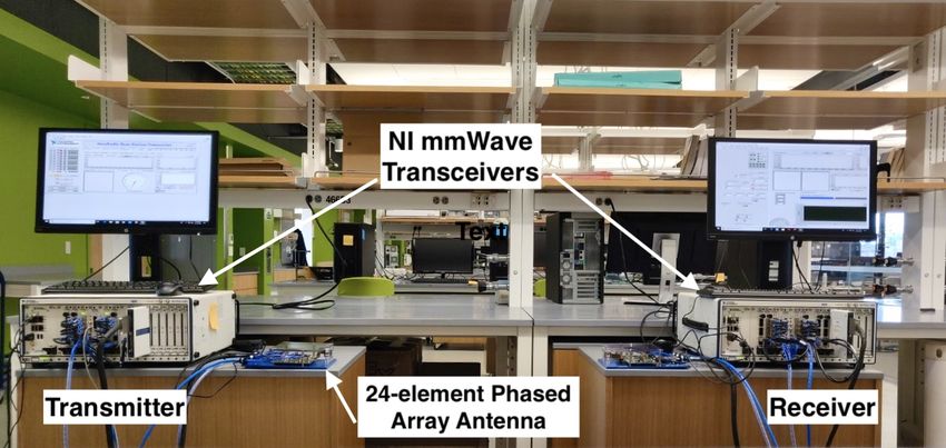
the geometric separation between them. We study the critical                                                         Transmission
                                                                                               Training Period
role of SNR spread among concurrently transmitting users as                     Probe                                Trigger

                                                                                                                                                                       ACK
                                                                                                                                                                 ACK

                                                                                                                                                                             ACK
                                                                                        ...
determined by multi-user beam selection, and show how it                   AP
                                                                                                beacons
helps in limiting inter-user interference and leads to increased           U1
                                                                                                                         Preamble                         Data
                                                                                                          feedback
SINR for each user and increased gains of UMBRA. Lastly,                                                                            Preamble              Data
                                                                           U2
we explore how increasing receive beamwidth at the AP
                                                                                                                                               Preamble   Data
can increase aggregate rate for UMBRA via increased SNR                    U3

diversity and beam selection efficiency.                                                      Fig. 2: Different stages of UMBRA timeline model

                         II. UMBRA F RAMEWORK                             are described in Section III. Because training need not im-
                                                                          mediately precede the transmission, we depict a potential
   In this section, we describe the key components of UMBRA
                                                                          discontinuity in the timeline.
for realizing uplink multi-user multi-stream transmission on a
                                                                             Uplink transmission in UMBRA begins with a group an-
single RF chain AP.
                                                                          nouncement trigger when the AP wins contention to serve
A. System Architecture and Timeline                                       a target set of users. The receipt of this trigger serves as a
                                                                          coarse initial time synchronization. The trigger identifies the
                                                                          users to be served, the beams that they should use, and the
                                                                  User    order for preamble staggering. As shown (not to scale), the
                                                                          users transmit staggered preambles. This allows the AP to
                                                                   RF     receive each preamble corresponding to each stream without
                                                                  Chain
                                                                          interferences which in turn enables estimation of CFO, symbol
      AP                                                                  timing and other channel parameters necessary to decode
                                                                          different streams. Finally, the clients transmit the data in
    Baseband      RF
                                                                          parallel followed by ACKs.
    Processing   Chain                                                       The AP uses its single RF chain to receive a superposition
                                                                          of data streams transmitted from multiple users. In order for
                                                           User
                                                                          the AP to decode these concurrent data streams from the
                                                                          composite signal, we design a SIC framework at the AP to
                                                                          train its receiver to perform stream separation. Typically, SIC
                                                           RF
                                                          Chain           consists of an iterative receiver, i.e., it decodes one stream
                                                                          at a time, whereas the remaining streams are considered
                                                                          interference. Then, after decoding a particular stream, its
                                                                          contribution to the overall signal is reconstructed and removed
Fig. 1: AP with single RF chain system supporting multiple users on the
uplink                                                                    from it. This procedure continues until all streams are decoded.

   Here, we describe a 60 GHz WLAN architecture that                      B. Scalable Multi-User Overlayed Constellations
supports simultaneous uplink users and steams exceeding the                  We present Multi-User Overlayed APSK Constellations for
number of RF chains at the receiver. We describe a special                UMBRA in which an APSK constellation with a varied param-
case of a single RF chain system with simultaneous reception              eter configuration represents the data stream corresponding to
from more than one user at a time.                                        each transmitting user and the AP receives an overlay of these
   Figure 1 shows the system model that coordinates and                   constellations from multiple users. In particular, we design an
supports multi-stream transmissions on the uplink. As shown,              overlayed constellation which defines the configuration of the
each user requires only a single RF chain driving a set of phase          APSK constellation (and hence MCS level) for each user. The
shifters, each controlling the phase of one antenna element, to           AP will assign one or more APSK rings, each with a specified
be able to independently beam steer a single data stream. The             number of symbols per ring, to each client. At the receiver,
application of different phase delays to the different antenna            this will yield an overlayed constellation yielding comprising
elements generates a directional beam. The set of possible                all rings. Thus, to enable efficient decoding, the AP must
beams (or equivalently phase delays) is fixed and is typically            assign rings such that different user’s rings are sufficiently
chosen from a predefined codebook. The beam width and                     separated. While this could in principle be achieved with client
beam direction are selected from one of these codebook entries            power control, we instead use beam steering and user selection
for each stream transmission. The AP has a single RF chain                to ensure that sufficient SNR spread is available. Moreover,
and is constrained to receive data streams from multiple users            our design allows the phase orientation of each ring to be
on a single receive beam. The AP must also select its beam                different, reducing synchronization requirements, and enabling
from a pre-defined codebook.                                              asynchronous decoding.
   UMBRA’s high-level timeline is depicted in Fig. 2. As                     More specifically, we assign different users to different
shown, prior to transmission we consider that beam training               sets of APSK constellations with an SNR ordering such
has occurred. The precise test transmissions and feedback                 that increasing SNR clients are assigned constellations with
I
UN
I 16.9o 0111 22.5o
Decision
re
1011 1001 0001 0011
rd
region 0011 Decision
U3 0101
region
go
0110
1010 1000 0000 0010
din
0100 0010
co
1101 0001
1100 0000
De
1110 1100 0100 0110 Q
Q
R
SN
1110 1000
U2 ng 1010
1111 1101 0101 0111
si
1111 1001
ea
cr
1011
U1
In
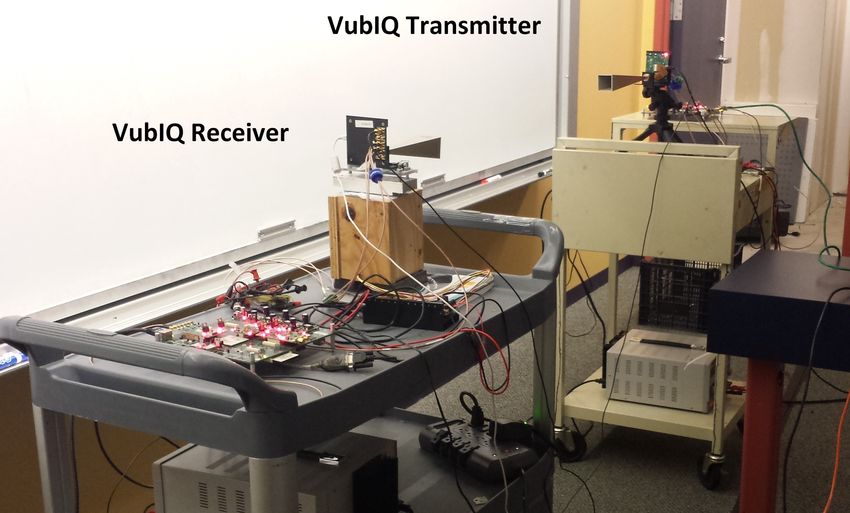
Fig. 4: Comparison of maximum angle error tolerance for symbol ’0011’ sent
using (Left) 16-QAM. (Right) 16-APSK.
receiver enhanced with the following capabilities (i) multi-
Fig. 3: (Left) Multi-user Overlayed APSK constellations showing users with user CFO correction comprised of a combination of pre-
constellation rings of increasing radius.(Right) SNR based SIC decoding order.
compensation and iterative correction, and (ii) interference
increasing radius. This is illustrated in Fig. 3 (left) where the filtered stream separation.
users are arranged in increasing order of SNRs. In the example, More specifically, after CFO estimation for all streams and
user U1 has lowest SNR and is assigned BPSK (here viewed as once the AP determines which stream to decode (in SNR
a one-ring constellation or 2-APSK). Likewise, U3 has higher order), the AP applies CFO correction of the current stream to
SNR than U1 and is assigned an 8-APSK constellation via the entire composite signal. Next the SIC receiver decodes the
two 4-APSK rings. This design of increasing SNR ordering current stream using an interference alleviation filter which is
of the users as shown in Fig. 3 (right) presents UMBRA the constructed from user-specific preambles and aims to recover
ability to better separate the user streams (rings) using ordered this signal and cancel the unknown interference from other
SIC decoding. Namely, the AP will first decode the stronger users. After removing the decoded signal component from
and more robust user with higher SNR, therefore reducing the the original composite signal, the applied CFO correction is
number of errors propagated from one stage to another. removed from the composite signal. This process is repeated
The performance of stream demultiplexing of UMBRA using until all streams are decoded. More formally, in what follows
SIC is highly dependent on two factors: (i) The relative signal we focus on decoding the signal from user i.
strength (SINR) of current user stream, i.e., difference between Multi-User CFO correction: Let si (n) be the time domain
the power of the signal being decoded and the interference plus symbol n transmitted by the ith user, and hi (n) be the channel
noise components of the composite signal. (ii) As the users impulse response of the ith channel. The signal of the ith user
and the AP do not share a common clock, the transmission after passing through channel is xi (n) = si (n) ∗ hi (n). The
trigger may not always guarantee a fully synchronized trans- composite received baseband signal is given as
mission thus leading to asynchronous reception of multiple XN
user data streams. The impact of both these factors would y(n) = xi (n)ej2π∆fi n + w(n) (1)
manifest as phase noise and non-linear distortion and causes i=1
rotation of the current symbol being decoded on each ring. where N is the number of users transmitting simultaneously
However, in our design, the distortion of the signal of one to the AP, and ∆fi denotes the ith user’s CFO normalized
user constellation ring due to inter-stream interference from by symbol period. Assuming that the AP decodes user i, it
other user constellation rings tends to have less effect on will correct CFO in time domain by multiplying y(n) with
the Euclidean distance between the symbols compared to an the term e−j2π∆fi n . After an iteration, the composite signal
alternate assignment such as QAM. Namely, if we overlayed after correcting the ith user is given by
QAM, the outer constellation points would be more sensitive c(n) = y(n)e−j2π∆fi n
to phase variations and nonlinear distortions associated with
= xi (n)(1) + xk (n)ej2π(∆fk −∆fi )n + · · ·
inter-stream interference and various sources of RF impair-
ments. In contrast, we assign different users to concentric rings + xN (n)ej2π(∆fN −∆fi )n + w0 (n) (2)
of constant amplitude to better tolerate the same amount of The AP can decode the ith user’s stream from the composite
phase variations. This is illustrated with an example in Fig. 4 signal using the filter described next.
which shows the maximum angle error tolerance for a symbol Signal Decoding using Interference Alleviating Filter:
’0011’ transmitted using 16-QAM and 16-APSK would be We model the received baseband signal vector from Equation
±16.9◦ and ±22.5◦ respectively. (2) as Xk6=i
C = Hi Si + Hk Ik + W (3)
C. Multi-User Stream Demultiplexing
k∈N
While the AP’s trigger coordinates the multi-user uplink where Si is the signal from user i and Ik is the interfering
transmissions and provides coarse-grained synchronization, signal from user k(k 6= i).
there are additional offsets due to different propagation de- An interference alleviating filter Pi exclusively designed
lays and CFOs. Here, we present how UMBRA can separate from preambles of user i can be employed to decode Si . The
the multi-user overlayed APSK constellations with the SIC estimated signal from user i can be denoted asŜi = Pi H C. (4) reception to find the highest SNR transmit beam from the AP.
The optimal filter can be derived by solving the mean squared The AP’s highest SNR sector is identified by the user and fed
error (MSE) optimization and is given as back in a control message. Conversely, user u sweeps though
its Cu beams while the AP is in quasi-omni receive mode in
Pi = E[CCH ]−1 E[CSi H ]. (5) order to find the user’s highest SNR beam. The AP similarly
We take advantage of the preamble symbols sent by each user i feeds this information back to the user. This training yields the
and estimate E[CCH ] and E[CSi H ] using statistical averaging best bi-directional AP-user beam pair via a total of CAP + Cu
operation over the preamble symbols [S̃i (1), S̃i (2), · · · , S̃i (L)] test transmissions and two feedback messages.
of user i and the received preamble symbols at the AP In contrast to solely feeding back the ID of the maximum
[C̃(1), C̃(2), · · · , C̃(L)] which also include the interfering SNR sector, UMBRA requires clients to feedback the SNR
signals from other users. This is given as of all measured sectors. This enables the AP to re-steer its
L
1X receive beam in a way that yields the best SNR spread and
E[CCH ] ← C̃(l)C̃(l)H (6)
L aggregate throughput. In our design, the AP does not need to
l=1
L feed back SNR-sector measurements to the clients: In UMBRA,
1 X
if a client should re-steer to further increase throughput, the
E[CSi H ] ← C̃(l)S̃i (l)H (7)
L AP will notify the client which sector to use in the trigger
l=1
message. Thus, UMBRA does not require additional training
In order to decode the signal from user i at the AP, the filter Pi
compared to 802.11ad, but does require a more rich feedback
is constructed using Equation (5) and then estimate the signal
message from clients to report the results of the training.
using Equation (4). After the first stream has been decoded, the
We define computational cost as the number of beam
composite signal is multiplied by ej2π∆fi n to remove the CFO
combinations that must be compared at the AP. If only the AP
component of the ith user’s stream. This process is continued
re-steers, it must check all of its receive beams and select the
for the rest of the users until all streams are decoded.
Lastly, we have found with symbol level simulations that beam with the maximum rate, a computation that is O(CAP ).
symbol offset due to propagation delay differences has a If one or more clients are allowed to re-steer, then there
relatively minor impact on the decoding reliability of UMBRA are additional computations required at the AP. Below, we
provided user streams are decoded with a sufficient SNR introduce policies which vary in their computation cost, but
spread. For example, with SNR difference of at least 9 dB, all require the same feedback as above.
the AP achieves a BER of 10−5 to decode the overlay B. All-Node Re-steering for Rate Maximization
constellations of 4-APSK and 2-APSK streams received with Here, we present All-Steer as a UMBRA beam selection
a maximum propagation delay of up to 1 µs and CFO of policy that specifies for each uplink transmission, the transmit
400 Hz. Hence, we do not compensate for this effect. and receive beams (codebook entry) to be used and the
III. C ONSTRAINED B EAM A DAPTATION modulation and coding scheme for each data stream at the
user. This policy targets to maximize the aggregate rate of a
Because UMBRA decoding is improved with high SNR
user group without any constraints on computational overhead.
spread among users, we employ beam steering at the clients
We consider N users selected for uplink transmission. Let
and AP to ensure sufficient SNR spread. In our system
bj ∈ CAP denote the beam index in the AP codebook and
architecture, the AP is constrained to use a single receive beam
bk ∈ Cu denote the beam index in the user’s u codebook. The
from its predefined codebook to receive a superposition of data
input to the beam selection policy is the training information
streams. Moreover, while the AP and all clients have previ-
for each user that comprises the measured signal-to-noise ratio
ously been trained for single-user transmission, these beams
(SNR) for each beam pair SNRu (bj , bk ), computed as the sum
that maximize the SNR for single user transmission may not
of the respective SNRs measured with one node in pseudo-
be the best beams for multi-user transmission. Thus, some
omni reception. The achievable data rate Ru (bj , bk ) by user
beams may need to be re-steered to improve the aggregate
u on each beam pair can be expressed as
multi-user rate. In this section, we describe UMBRA’s AP and
client beam selection with a joint focus on aggregate rate and Ru (bk , bj ) = MCS(SNRu (bk , bj )) (8)
overhead. We describe policies in which some or all users are where MCS(·) gives the data rate achievable for a particular
prohibited from re-steering their beams in order to not incur SNR via the single-user minimum SNR tables.
computation overhead. In Single User transmission, the AP maximizes the single-
user rate by choosing the beam pair having maximum
A. Training and Computational Overhead
SNR. We denote this Single User beam pair for user u as
In single-user 802.11ad beam training, the sender sequen- (bmax max max
k,u , bj,u ) and the corresponding Single User rate as Ru
tially transmits on each of its sectors (codebook entries) and and it is given by
the receiver subsequently identifies and feeds back the ID
of the sector that yields the highest SNR. For example, the (bmax max
k,u , bj,u ) = arg max SNRu (bk , bj ) (9)
(bk ,bj )
AP first sends training frames sequentially on all CAP of its
codebook entries (beams) while the user employs quasi-omni Rmax
u = MCS(SNRu ((bmax max
k,u , bj,u )). (10)U2 U2
U2
SU optimal
AP
beam
AP
AP
U1
U1
SU optimal U1
SU optimal
beam
beam
Fig. 5: Illustrative scenario of constrained beam adaptation using (Left) All-Steer. (Middle) AP-Steers. (Right) Freeze-Subset.
Let G be the user group to be triggered by the AP. the users use their best TX beam under all AP receive beams.
All-Steer must determine the best user beams {bk,u }u∈G to Subsequently, the AP finds the final receive beam b∗j by
transmit to a shared receive beam bj at the AP. Such beams performing a search among all the possible combinations of
will be those that result in highest SNR spread and thereby candidate receive beams at its end. Note that this policy does
maximum achievable aggregate rate for the receive beam bj not introduce additional overhead for user beam selection as
and these beams may not be the best Single User beam pair the SNR associated with each beam is already available at the
(bmax max
k,u , bj,u ). The objective of All-Steer is as follows AP after initial beam sweeps. Hence, the maximum computa-
X tional cost at the AP to find the best analog configuration is
(b∗j , {b∗k,u }u∈G ) = arg max Ru (bk , bj ) (11a) O(CAP ). Fig. 5 (middle) depicts the AP-Steers beam selection
u mechanism in which the two users use their best transmit
s.t. bk,u ∈ Cu , u ∈ G (11b) beams as the AP re-steers at its end to find the best receive
bj ∈ CAP . (11c) beam with maximum SNR spread and thereby the aggregate
rate.
Equation (11a) optimizes the beam selection to maximize the
sum rate by finding the best receive beam at the AP b∗j that D. Freezing a Subset of Users
could be shared by all the users in the group G while each Here, we present a final UMBRA strategy that represents a
user u ∈ G will be using their best transmit beam {b∗k,u } balance between All-Steer and AP-Steers. Namely, we present
for the selected receive beam. Furthermore, the maximum Freeze-Subset as a policy that significantly reduces the search
aggregate rate resulting from this beam selection is achieved space of All-Steer by exploiting the fact that grouped users
only when sufficient SNR spread is available as this enables with maximum aggregate rate are typically composed of
efficient decoding with maximal separation among the inter- streams having high SNR spread. Furthermore, if all users
user rings as discussed in Sec. II-B. The two constraints ensure have the same SNR, UMBRA cannot realize a gain over
that the transmit and receive beams are selected from the Single User as there is no SNR margin between the users
predefined user and AP codebooks respectively. Fig. 5 (left) to counteract the inter-user interference and improve decoding
depicts an example scenario where All-Steer jointly optimizes reliability. Hence, Freeze-Subset avoids computing all possible
the beam selection by enabling the AP and the two users to beam combinations by choosing a subset of users from the
simultaneously beam steer to create sufficient SNR difference target user group to re-steer jointly with the AP to find the
for successful stream decoding and targets to increase the sum optimal multi-user beam configuration that targets to maximize
rate if possible. Computationally, with All-Steer, the optimal the SNR spread and potentially increase aggregate rate. The
solution of Equation (11) yields to an exhaustive search over remaining non re-steering users in the group freeze their
all possible AP-user beam tuples combinations. Hence, the transmit beams to share the common receive beam at the AP.
AP findsQGthe final beam configuration by checking a total of More formally, we define Freeze-Subset as follows. For
CGAP · u=1 Cu distinct beam combinations and then feeds a target set of grouped users G, Freeze-Subset first sorts
back the final beam IDs to the re-steering users. users in decreasing order of their maximum single-user SNR
corresponding to their best beam pair (bmax max
k,u , bj,u ) with the
C. AP Only Re-Steering first sorted user having the highest SNR. Freeze-Subset begins
To obtain the maximum aggregate rate using All-Steer, we with an initial “prime user” to re-steer with the AP, while
need to exhaustively search every combination of the beams at the other users are held to their best transmit beams for the
AP and the target set of users. Unfortunately, implementation chosen AP receive beam. While any user can be a prime user,
of this exhaustive search may not be practical in real scenarios we select the user having the highest SNR as the prime user
due to the high computational overhead. as this user will be decoded first using SIC to have control on
Here, we introduce AP-Steers as a policy on the other end the inter-user interference and reduce decoding propagation
of the design spectrum. Namely, in order to limit the search errors. Freeze-Subset iterates the same procedure by searching
overhead, only the AP re-steers while all the users in the for other users in the group to re-steer jointly with the AP
group G freeze their best transmit beams {bmax k,u }u∈G found and can form a higher aggregate rate multi-user transmission
during the initial beam training. Namely, the AP picks the top with the existing users. Finally, at the end of beam selection
candidate set of receive beams that are optimal in potentially process, the AP notifies the re-steering users with their final
maximizing aggregate rate for multi-user transmission while beam IDs. Let g ⊂ |G| denote the final outcome of numberTransmitter
Horn Antennas
Receiver
Motion Control
WARP
WARPBoard
Board
Fig. 6: (Left) X60 testbed with mmWave transceiver and phased array antenna. (Middle) X60 Irregular azimuth beam pattern. (Right) WARP-60 testbed with
horn antennas.
of users in Freeze-Subset that freeze their beams and not re- strong side-lobes. We collect channel samples from over-
steering with AP. Namely, g = |G| corresponds to the case of the-air measurements and subsequently perform trace-driven
AP-Steers where all users have frozen their beams and only AP emulation to study UMBRA. More details on this methodology
re-steers and g = 0 corresponds to the case of All-Steer where are presented in Sec V.
none of the users freeze their beams and all re-steer along with
the AP. Therefore, computationally, Freeze-Subset performs up B. WARP-60 Horn Antenna Platform
|G|
(CAP × Cu )|G|−g tests of aggregate rate to find the
to |G|−g While X60 enables experiments over wideband channels
final beam configuration among the users in G. Fig. 5 (right) and a practical phased-array, the beamwidth is limited to 25◦ .
depicts an example scenario using Freeze-Subset when one of Hence, to evaluate UMBRA under changing beamwidth, we
the users i.e., |G| − g = 1 perform joint beam steering with integrate a WARP horn antenna platform with a 60 GHz front
the AP to target to increase the aggregate rate. The other user end into our testbed form from [6], [7]. The horn antennas’
freezed its best transmit beam for the chosen receive beam at regularly shaped beam patterns can emulate beam forming of
the AP. a many-antenna phased array. In particular, we use the testbed
setup in Fig. 6 (right) which consists of commercial mm-wave
IV. E VALUATION S ETUP : T ESTBEDS AND OVER - THE - AIR transmitter and receiver modules from the VubIQ 60 GHz
EXPERIMENTS development system, WARP v1 boards and daughter boards
In this section, we present our implementation of key com- for signal adjustment. These modules can communicate in
ponents of UMBRA and collect over-the-air data to evaluate the 57-64 GHz unlicensed band with up to 1.8 GHz signal
its performance. As our evaluation encompasses scenarios to bandwidth and can accept and output I/Q baseband signals.
study the impact of various parameters such as beamwidth, To achieve directional beams of varying beamwidth, we use
antenna array beam patterns and multi-user capability, we 7◦ , 20◦ and 80◦ horn antennas. To implement beam-steering,
employ two different platforms, X60 and WARP-60 enhanced TX-RX nodes (depicted in Fig. 6 (right)) are mounted on com-
with a 60 GHz front end. merical motion control setup which enables rotation to sub-
degree accuracy. Using this WARP-60 system, we measure the
A. X60 Phased Array Platform SNR of a point to point transmission and perform numerous
We perform over-the-air experiments with X60, a config- measurements varying the user location, antenna beamwidth,
urable Software Defined Radio based mmWave platform [4]. and use this data to study the performance of UMBRA.
X60 features a fully programmable cross-layer architecture for
V. E XPERIMENTAL E VALUATION
PHY, MAC and Network layers. Fig. 6(left) shows the X60
platform where each X60 node is built with National Instru- In this section, we perform over-the-air measurements to
ments’ (NI) millimeter-wave transceiver system and employs a evaluate the performance of UMBRA and compare to baseline
user configurable SiBeam phased array antenna module with schemes.
24 elements, 12 for TX and 12 for RX. Communication is
established over wide-band 2 GHz channels that can reach A. Impact of Geometry Between Grouped Users
multi-gigabit data rates using real-time electronically steer- The spread in signal strengths among concurrently trans-
able (switching time of 1µs) TX and RX beams from a mitting users affects the successful decoding of the composite
predetermined codebook consisting of 25 beams which are stream at the AP. More specifically, the relative signal strength
spaced roughly 5◦ apart along the mainlobe direction, thereby of all users as determined by the beam selection can be
covering a sector of −60◦ to 60◦ in the azimuthal plane influenced by geometry of users and this affects the SIC user
centered around the antenna’s broadside direction. Each beam decoding order by allowing the AP to first decode the stronger
has a 3 dB bandwidth of 25◦ to 35◦ causing each main-lobe to and more robust users, therefore, reducing the number of errors
overlap with other neighboring beams. Therefore, it is evident propagated from one stage to the other. To demonstrate this,
as in Fig. 6(middle) that X60 provides irregular and imperfect we consider a simplified setting of two users transmitting in the
beam patterns with predominant main lobes overlapping and uplink and study both the impact of geometry on the ability ofSU AP-Steers Freeze-Subset All-Steer
window 9
6
Pillar 7.5
Aggregate capacity (bps/Hz)
6
15 12 9 5
4.5
4
window
E 3
14 11 8 3 N S 1.5
W
2m 2 0
Vertical Diagonal Lateral
1m
13 10 7 1 AP Fig. 8: Average aggregate capacity for different user groups
1.5m 3.3m
Pillar Pillar Aggregate rate. Figure 8 shows the aggregate capacity ob-
tained by the three user group categories under different beam
Fig. 7: Experimental floor plan used for measurement of data using X-60 selection policies. First, the Single User scheme achieves an
testbed.
average capacity of 5.7 bps/Hz across all user group categories
the AP to decode the different user streams. We conduct over- with the lowest capacity obtained by lateral groups due to
the-air experiments using the X-60 testbed and experimentally the impact of both angular separation and distance leading
explore the multi-user gains of UMBRA in comparison to to SNR loss at U2 and hence decrease in contribution to the
Single User transmission scheme. aggregate capacity; while the highest capacity is obtained by
Setup. We deploy X60 nodes as depicted in the scenario in vertical groups in which both the grouped users have high
Fig. 7 which includes the AP and 15 different user locations. SNR (best MCS) links. Thus the performance of Single User
The AP is fixed at one corner of the lobby at a height of scheme depends on the geometry of transmitting users.
1.23 m facing North and all users are at the same height Second, AP-Steers has marginal gains over Single User
facing South. The presence of windows and metal coating scheme for vertical user group. In particular, as the inter-user
beneath them (not shown) create reflections. For each AP- distance increases, due to the presence of strong reflection
user position, we collect SNR for all possible 625 (25 × 25) from sidewalls and overlapping beams, the high SNR at
beam-pair combinations. both the users remains steady over a larger range of beam
Two User uplink with UMBRA. In this experiment, we steering directions before dropping below 0 dB. The users
consider a two-user group for simultaneous uplink transmis- use the beam 0 which is the best TX beam for both the
sion and can share a common receive beam at the AP via users. It was observed that for this beam, the maximum
UMBRA. The first user U1 is fixed, 3.3 m apart from the achievable SNR diminishes only for higher beam steering
AP and second user U2 can be placed in any of the marked angles on either side of central beam at the AP. This is
positions 2-15. To study the impact of geometry in terms of a consequence of the non-uniform angular spread of beams
distance and angular separation between U1 and U2 , the user and diminishing directivity gain of beam indices only farther
groups have been divided into three categories as highlighted from central beam, a limitation of practical phased array
in Fig. 7: (i) vertical user groups consist of U2 (7,10,13) antennas. Therefore the optimal beam selected by the AP
vertically separated from U1 , (ii) lateral user groups consist results in high SNRs at these users and thereby excessive inter-
of U2 (2,3,4,5,6) that has lateral separation with U1 , and (iii) user interference. The rates improve for diagonal and lateral
diagonal user groups as U2 (8,9,11,12,14,15) has diagonal user groups in which with increasing inter-node distance, U2
angular separation and increasing distance with U1 . experiences SNR degradation for almost all beam steering
Aggregate rate calculation. For all two-user combinations directions chosen at the AP. Moreover, angular separation has
in each category, we find the PHY capacity of a two-user a pronounced impact than that of distance and thus results in
uplink communication as follows: For each user group and SNR loss. From decoding perspective, this SNR loss translates
potential multi-stream analog beam configuration, we compute to the effect of having low inter-user interference on U1 and
the expected SNR at U1 and U2 , then the AP selects the thereby increasing the aggregate rate in these user groups.
MCS index for each user whose corresponding SNR ≤ SNR Third, Freeze-Subset achieves 1.22×, 1.47× and 1.49×
threshold as computed in the APSK two-user minimum SNR multi-user rate gains over Single User scheme for vertical,
decoding tables. The corresponding number of data bits per diagonal and lateral user groups respectively and has perfor-
symbol is the per-user capacity (each stream can use a different mance close to 96% of the All-Steer policy across all user
MCS but we maintain the same coding rate for the two groups despite its significantly reduced search space. This is
streams). For comparison, we also implement the Single User because the AP and one of the users re-steer jointly to discover
transmission scheme. Single User aggregate capacity is mea- a multi-user beam. This policy exploits the combined effect
sured by considering that the two users U1 and U2 each get of the non line of sight (NLOS) paths due to usage of wide
half of the air time. The AP uses it best receive beam for U1 beamwidths, non-uniform angular spread of beam patterns and
and U1 uses its best transmit beam. The best TX-RX beam diminishing directivity gain of beams for all angles of the user
pair is likewise used for U2 . Unlike the multi-user case, the to the advantage of increasing the SNR spread and therefore
AP can select different receive beams for U1 and U2 . results in increased sum capacity. Moreover, the rate gains alsoAP-Steers Freeze-Subset All-Steer
20 White board
4 3 2
SNR Difference (dB) 5 1
15
5.6 m
AP
10
Table
6 10 TV
7 8 9
5 AC
Glass window
5.72 m
0
Vertical Diagonal Lateral Fig. 10: Experimental floor plan used for measurement of data using WARP-
Fig. 9: Received SNR difference for different user groups 60 testbed.
highlight that at-least one of the users should re-steer with low even with high angular separation at U2 .
the AP to find the beams that efficiently tackle the inter-user With Freeze-Subset there is an increase in the SNR differ-
interference and potentially increase the sum capacity. ence and thus higher sum rate over AP-Steers and Single User
Finally, All-Steer achieves approximately 1.3×, 1.52× and schemes. Here the joint beam steering at the AP and one of the
1.5× multi-user rate gains over Single User scheme for ver- users offers more flexibility to choose beams that are optimal
tical, diagonal and lateral user groups respectively. This is in multi-user setting. We observe that as the achievable SNR
attributed to the fact that with large (∼ 30◦ ) beamwidth and difference increases, the SINR at U1 increases with increasing
presence of strong side-lobes giving rise to more flexibility separation between U1 and U2 thus causing lower inter-user
of choosing beams and with AP and the two users jointly interference.
re-steering, this policy creates huge number of beam-sharing All-Steer checks all the possible beam combinations and
opportunities such that majority of the beams have highest efficiently exploits the SNR disparity among the users. Al-
potential to increase the sum capacity. Theoretically, All-Steer lowing all the nodes to re-steer resulted in reduced inter-
should achieve close to 2× gains over Single User; however, user interference as these nodes jointly discover the beam that
this does not hold true for every user group in the setup. This provides greater SINR boost and consequently capacity boost
is because we find in the measurements that the SNR along even in case of high SNR links between the users.
the beams of NLOS paths is typically lower than the LOS C. Impact of increased beamwidth
paths. Hence, even if the inter-user interference is efficiently In this experiment, we illustrate the impact of increas-
managed by choosing the best beams (mix of both NLOS and ing beamwidth on the performance of UMBRA. Narrow
LOS) at AP and users, the aggregate capacity of two user beamwidth achieves maximum signal strength due its higher
group might not obtain 2× gain over Single User. Although directivity gain. However, in case of mobility, there is sig-
this policy requires exhaustive search to find the optimal multi- nificant degradation in link strength and leads to increased
user beam, nonetheless it offers aggregate capacity ≤ 8.8 overhead due to high frequency of beam sounding. In contrast,
bps/Hz and achieves more than 1.35× gain over Single User wider beams offer lower link budget and can reduce SNR
across all user groups indicating that sum capacity increases and data rate but provide greater resilience to mobility and
with increasing number of simultaneous beam steering nodes. sufficient signal strength across a larger spread of TX-RX
relative angles. This implies that the presence of reflected paths
B. Role of SNR Difference Between Grouped Users in addition to the LOS paths, makes the wider beamwidth
Here, we explore how with the advantage of performing much resilient to blockage or misalignment while the signal
beam selection using UMBRA, we can create sufficient SNR spread of narrower beamwidths is not sufficient to exploit this
diversity among the users that can enable the AP to suc- additional paths. Therefore, wider beamwidth can also exploit
cessfully separate the user streams and manage inter-stream multiple paths in addition to a much wider reception signal
interference. We use the same node deployment as in Fig. 7. along the LOS paths, thereby providing better beam selection
Figure 9 shows the SNR difference obtained by all the possibilities and yielding more opportunities to achieve maxi-
multi-user beam selection policies under study. As shown, mum aggregate rate via UMBRA. To explore this beamwidth-
the beams selected with AP-Steers for vertical groups resulted signal coverage tradeoffs, we employ the WARP-60 testbed
in a negligible SNR difference which may be insufficient to which generates directional beams of varying beamwidth using
separate and successfully decode the composite user stream horn antennas.
at the AP. Moreover, a very slight improvement in SNR Setup. We consider the experimental floorplan as shown in
difference arises from diagonal and lateral user groups having Fig. 10 We fix the AP location at one end of the conference
angular separation and distance. However, the improvement is table. We place the users in 10 different positions. We select
not high enough that could lead to a significant rate increase the 20◦ horn for the user’s receive antenna to meet the size and
as seen in Fig. 8. The reason is that sometimes the receive power constraints in the mobile user. For each user position,
beam selected by the AP has a powerful sidelobe pointing we perform a 360◦ sweep of the AP in steps of 5◦ and at each
towards U2 which results in interference power from the U2 point of AP’s sweep, we take RMS baseband measurements
being equal to the signal power and thus the SINR at U1 is to estimate the SNR. We conduct the AP’s sweep using 7◦ ,8
SU AP-Steers Freeze-Subset All-Steer transmissions with the AP using atleast one RF chain per
stream [1], [6], [8], [9]. However, all these systems are
Average Aggregate Capacity (bps/Hz)
6 limited to downlink transmissions and not applicable to uplink.
Although a significant amount of research has focused on
4
theoretical capacity analysis for mmWave uplink [10]–[13],
little is known about the performance of such systems in prac-
2
tice. UMBRA in contrast, realizes the first mmWave WLAN
0
system design and experimentation in which the number of
Beamwidth 7◦ Beamwidth 20◦ Beamwidth 80◦
users exceeds the number of RF chains.
Fig. 11: Average of the aggregate capacity for all the users in the setup Multi-User Uplink Sub 6 GHz Networks. Prior work
20◦ and 80◦ horns. In order to study the multi-user capacity on uplink MU-MIMO below 6 GHz focus on information-
gains of UMBRA, we assume a two stream transmission and theoretic capacity exploration [14], [15], multi-user trans-
consider all possible user groups consisting of 2 users out of mission via successive interference cancellation, interference
10 (i.e., a total of 10
2 different user groups). In all topologies,
alignment or orthogonal preambles [16]–[20]. Unfortunately,
both the users always have LOS connectivity with the AP. techniques used in these works can’t be applied to our scenario
Beamwidth and Aggregate Rate. Figure 11 shows the due to a different node architecture at 60 GHz (lacking one RF
aggregate rate of each beam selection policy averaged over chain per antenna), we can only acquire a composite channel
all two-user groups for different receive beamwidths at the at the RF chain, where signals from multiple antenna elements
AP. First, as expected, for the narrowest beamwidth of 7◦ , are mixed.
beam steering provides higher antenna gain due to AP’s more Multi-user Uplink with Single RF Chain. Extensive prior
focused beams and consequently yielding high Single User work in uplink has realized MU-MIMO while requiring a
SNRs that most of the users are served with their best possible single RF chain. [21]–[23]. More recently, NOMA has been
MCS. While in principle, an extremely narrow beamwidth used in mmWave Uplink which has the same philosophy of
would not be useful for multi-user grouping, this was not overlayed constellations of using same time, frequency and
the case in our experimental setup. UMBRA provides modest space resources [24]–[32]. Furthermore, user streams are sep-
multi-user gains even in this case of 7◦ beams with AP-Steers, arated via power allocation policies and employ SIC at receiver
Freeze-Subset and All-Steer policies providing an aggregate to remove the multi-user interference. Instead, we address the
rate improvement over Single User by 5%, 22% and 40% stream separation with design of multi-user overlayed ASPK
respectively. constellations and multi-user stream decoder and rely on beam
Second, as the beamwidth increases to 20◦ , there is a signifi- steering and user locations to enable SNR spread. In contrast
cant drop in the Single User average aggregate capacity due to to all prior work, our focus is not only the design of mmWave
the reduction in directivity gain owing to the inherent tradeoff uplink WLAN system, but we also experimentally evaluate the
between selected beamwidth and rate. However, increasing the functionality under practical system constraints and identified
beamwidth at the AP increases the beam sharing possibilities the key factors that affect the multi-user gains.
as UMBRA exploits the multiple paths in addition to the LOS VII. C ONCLUSIONS
paths. This in effect increases the SNR spread among the users
and reduces the inter-user interference making opportunity In this paper, we present the design and experimental
for the policies to boost the SINR at each user. Therefore, evaluation of UMBRA, a novel framework that supports multi-
the achievable aggregate rate of AP-Steers, Freeze-Subset and user uplink transmissions on a single RF chain AP. We intro-
All-Steer strategies is approximately 19%, 41% and 62% duced Multi-User Overlayed APSK constellations for enabling
higher than Single User respectively. simultaneous uplink transmissions of APSK signals with a
Third, the multi-user gains of UMBRA are more pro- design feature that allows multi-stream separation via SIC.
nounced in case of 80◦ beamwidth despite the highest drop in We designed the multi-user receiver with the mechanism to
Single User aggregate capacity. Fig. 11 reveals that AP-Steers, perform multi-user CFO correction and compensation and
Freeze-Subset and All-Steer strategies reflect more than 1.3×, interference cancellation filter based stream separation. We
1.5× and 1.7× multi-user capacity gains over Single User. proposed constrained beam adaptation that enables UMBRA
This is attributed to the fact that increased beamwidth in- to maximize aggregate rate under multiple system constraints.
creases the SNR diversity among the users and leads to huge Our experiments demonstrate that UMBRA achieves about
number of beam sharing opportunities and the number of 1.45× improvement in multi-user gains over single-user sys-
such potential beams that could result in maximum achievable tems irrespective of choice of users grouped, geometric sepa-
aggregate rate outweigh the former beams from usage of ration and receive beamwidth.
narrower beamwidth. VIII. ACKNOWLEDGMENTS
VI. R ELATED W ORK This research was supported by Cisco, Intel, and by NSF
Multi-User Uplink 60 GHz Networks. Prior work in grants CNS-1955075, CNS-1923782, CNS-1824529, CNS-
mmWave WLANs target downlink multi-user multi-stream 1801857.R EFERENCES cations With Analog Beamforming,” IEEE Transactions on Wireless
Communications, vol. 18, no. 7, pp. 3411–3423, 2019.
[1] Y. Ghasempour, M. K. Haider, C. Cordeiro, D. Koutsonikolas, and [24] H. Wang, R. Zhang, R. Song, and S. Leung, “A Novel Power Mini-
E. Knightly, “Multi-Stream Beam-Training for mmWave MIMO Net- mization Precoding Scheme for MIMO-NOMA Uplink Systems,” IEEE
works,” in Proc. of ACM MobiCom, 2018. Communications Letters, vol. 22, no. 5, pp. 1106–1109, 2018.
[2] . IEEE P802.11 TASK GROUP AX, “IEEE P802.11 Wireless LANs: [25] Z. Ding, R. Schober, and H. V. Poor, “A General MIMO Framework
Specification Framework for TGax,” IEEE Standard in Progress (2017), for NOMA Downlink and Uplink Transmission Based on Signal Align-
2017. ment,” IEEE Transactions on Wireless Communications, vol. 15, no. 6,
[3] D. Tse and P. Viswanath, Fundamentals of wireless communication. pp. 4438–4454, 2016.
Cambridge university press, 2005. [26] Z. Yang, Z. Ding, P. Fan, and N. Al-Dhahir, “A General Power Alloca-
[4] S. K. Saha, Y. Ghasempour, M. K. Haider, T. Siddiqui, P. De Melo, tion Scheme to Guarantee Quality of Service in Downlink and Uplink
N. Somanchi, L. Zakrajsek, A. Singh, R. Shyamsunder, O. Torres et al., NOMA Systems,” IEEE Transactions on Wireless Communications,
“X60: A programmable testbed for wideband 60 GHz WLANs with vol. 15, no. 11, pp. 7244–7257, 2016.
phased arrays,” Computer Communications, vol. 133, 2019. [27] M. S. Ali, H. Tabassum, and E. Hossain, “Dynamic User Clustering and
[5] N. Anand, E. Aryafar, and E. W. Knightly, “WARPlab: A Flexible Power Allocation for Uplink and Downlink Non-Orthogonal Multiple
Framework for Rapid Physical Layer Design,” in Proc. of the 2010 ACM Access (NOMA) Systems,” IEEE Access, vol. 4, pp. 6325–6343, 2016.
workshop on Wireless of the students, by the students, for the students, [28] M. A. Sedaghat and R. R. Müller, “On User Pairing in Uplink NOMA,”
2010. IEEE Transactions on Wireless Communications, vol. 17, no. 5, pp.
3474–3486, 2018.
[6] K. P. Dasala, J. M. Jornet, and E. W. Knightly, “SIMBA: Single RF
[29] X. Chen, A. Benjebbour, A. Li, and A. Harada, “Multi-User Proportional
Chain Multi-User Beamforming in 60 GHz WLANs,” in Proc. of IEEE
Fair Scheduling for Uplink Non-Orthogonal Multiple Access (NOMA),”
INFOCOM, 2020.
in Proc. of IEEE VTC- Spring, 2014.
[7] S. Naribole and E. Knightly, “Scalable multicast in highly-directional
[30] B. Kim, W. Chung, S. Lim, S. Suh, J. Kwun, S. Choi, and D. Hong,
60-GHz WLANs,” IEEE Transactions on Networking, vol. 25, no. 5,
“Uplink NOMA with Multi-Antenna,” in Proc. of IEEE VTC Spring,
2017.
2015.
[8] I. . W. Group et al., “IEEE 802.11 ad, Amendment 3: Enhancements for [31] Y. Gao, B. Xia, K. Xiao, Z. Chen, X. Li, and S. Zhang, “Theoretical
Very High Throughput in the 60 GHz Band,” December, vol. 1, no. 2, Analysis of the Dynamic Decode Ordering SIC Receiver for Uplink
2012. NOMA Systems,” IEEE Communications Letters, vol. 21, no. 10, pp.
[9] Y. Ghasempour, C. R. da Silva, C. Cordeiro, and E. W. Knightly, “IEEE 2246–2249, 2017.
802.11 ay: Next-generation 60 GHz communication for 100 Gb/s Wi- [32] Z. Wei, L. Yang, D. W. K. Ng, J. Yuan, and L. Hanzo, “On the
Fi,” IEEE Communications Magazine, vol. 55, no. 12, 2017. Performance Gain of NOMA Over OMA in Uplink Communication
[10] L. Zhu, J. Zhang, Z. Xiao, X. Cao, D. O. Wu, and X. Xia, “Joint Systems,” IEEE Transactions on Communications, vol. 68, no. 1, pp.
Power Control and Beamforming for Uplink Non-Orthogonal Multiple 536–568, 2020.
Access in 5G Millimeter-Wave Communications,” IEEE Transactions
on Wireless Communications, vol. 17, no. 9, pp. 6177–6189, 2018.
[11] P. Raviteja, Y. Hong, and E. Viterbo, “Millimeter Wave Analog Beam-
forming With Low Resolution Phase Shifters for Multiuser Uplink,”
IEEE Transactions on Vehicular Technology, vol. 67, no. 4, pp. 3205–
3215, 2018.
[12] J. Li, L. Xiao, X. Xu, and S. Zhou, “Robust and Low Complexity Hybrid
Beamforming for Uplink Multiuser MmWave MIMO Systems,” IEEE
Communications Letters, vol. 20, no. 6, pp. 1140–1143, 2016.
[13] O. Onireti, A. Imran, and M. A. Imran, “Coverage, Capacity, and Energy
Efficiency Analysis in the Uplink of mmWave Cellular Networks,” IEEE
Transactions on Vehicular Technology, vol. 67, no. 5, pp. 3982–3997,
2018.
[14] A. Goldsmith, S. A. Jafar, N. Jindal, and S. Vishwanath, “Capacity limits
of mimo channels,” IEEE Journal on Selected Areas in Communications,
vol. 21, no. 5, pp. 684–702, 2003.
[15] Y. Kim, S. Cho, and D. K. Kim, “Low complexity antenna selection
based mimo scheduling algorithms for uplink multiuser mimo/fdd sys-
tem,” in Proc. of IEEE VTC -Spring, 2007.
[16] K. Tan, H. Liu, J. Fang, W. Wang, J. Zhang, M. Chen, and G. M. Voelker,
“SAM: enabling practical spatial multiple access in wireless LAN,” in
Proc. of MobiCom, 2009.
[17] A. Zhou, T. Wei, X. Zhang, M. Liu, and Z. Li, “Signpost: Scalable
MU-MIMO signaling with zero CSI feedback,” in Proc. of MobiHoc,
2015.
[18] A. B. Flores, S. Quadri, and E. W. Knightly, “A scalable multi-user
uplink for Wi-Fi,” in Proc. of USENIX NSDI, 2016.
[19] K. C.-J. Lin, S. Gollakota, and D. Katabi, “Random access heteroge-
neous MIMO networks,” ACM SIGCOMM Computer Communication
Review, vol. 41, no. 4, pp. 146–157, 2011.
[20] T. Wei and X. Zhang, “Random access signaling for network MIMO
uplink,” in Proc. of IEEE INFOCOM, 2016.
[21] N. I. Miridakis and D. D. Vergados, “A survey on the successive
interference cancellation performance for single-antenna and multiple-
antenna OFDM systems,” IEEE Communications Surveys & Tutorials,
vol. 15, no. 1, 2012.
[22] M. Zeng, W. Hao, A. Yadav, N. Nguyen, O. A. Dobre, and H. V. Poor,
“Energy-Efficient Joint Power Control and Receiver Design for Uplink
mmWave-NOMA,” in Proc. of ICC Workshops, 2020.
[23] Z. Xiao, L. Zhu, Z. Gao, D. O. Wu, and X. Xia, “User Fairness Non-
Orthogonal Multiple Access (NOMA) for Millimeter-Wave Communi-You can also read