Pryda Timber Connectors - Hangers & Truss Boot Guide September 2016 - Newcastle Timber Trading
←
→
Page content transcription
If your browser does not render page correctly, please read the page content below
Pryda Timber Connectors
  Hangers & Truss Boot Guide

                            September 2016

A complete guide to the design, specifications and
    installation of Pryda Hangers and Truss Boots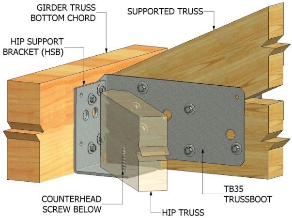
ESSENTIAL NOTES –
                          PRYDA PRODUCT GUIDES

INTRODUCTION
                                                                         CORROSION PROTECTION
The information in this Product Guide is provided for use in
Australia by architects, engineers, building designers, builders and     Most Pryda products are manufactured using Z275 light-gauge
others. It is based upon the following criteria:                         steel, having zinc coating of 275 gsm (total weight). This protection
                                                                         is adequate only for INTERNAL applications in most corrosive
 1. No Substitution: The products covered by or recommended              environments, except areas that are classified as heavy industrial
    in this guide must not be substituted with other products.           or those subject to high humidity (eg, enclosed swimming pools).
                                                                         Under these circumstances, seek advice from experts as special
                                                                         protection will be required. Note: INTERNAL areas are those within
 2. Design Capacity Basis: See Codes & Standards following.
                                                                         the building envelope that are kept permanently dry.

 3. Supporting Constructions: Constructions using Pryda                  AS1684.2-2010 and AS1684.3-2010, Australian Standards for
    products must be built in accordance with the NCC (BCA) or           Residential Timber Frame Construction stipulate a minimum
    an appropriate Australian Standard. Note: This includes              Z275 steel for all sheet metal products used in an internal
    appropriate corrosion protection- See Corrosion Protection           environment.
    following.

                                                                         In areas outside the building envelope that are exposed to
 4. Correct Installation: Installation of Pryda products must be         repeated wetting (EXTERNAL areas), Pryda’s stainless steel
    strictly in accordance with the instructions in this guide.          products or equivalent should be considered. Some alternatives
                                                                         include hot dip galvanised or powder coated steel, which are not
 5. Current Guide Version Used: The current version of this              supplied by Pryda. For more detailed information, read Pryda’s
    guide, including any amendments or additions, must be used.          Technical Update on Corrosion Resistance of Pryda Products or
    Users are advised to check the Pryda website,                        contact a Pryda office.
    www.pryda.com.au, on a regular basis for the most current
    design guides.                                                       PRODUCT CERTIFICATION
                                                                         Pryda Australia warrants:
CODES & STANDARDS
                                                                           •   Products in this guide are free from defects in the material
Product design capacities in this guide have been derived from:                and manufacturing
                                                                           •   Design capacities are in accordance with test results or
(a) Results of laboratory tests carried out by or for Pryda Australia
                                                                               current, relevant Australian Standards and the Building Code
(b) Engineering computations in accordance with the relevant                   of Australia.
   Australian Standards, ie:                                               •   Pryda products are structurally adequate provided they are
   •   AS1720.1-2010 Timber Structures. Part 1: Design                         designed, installed and used completely in accordance with
       Methods.                                                                this guide.
   •   AS/NZS1170 series Structural Design Actions.
   •   AS4055-2006 Wind Loads for Housing.                               This warranty applies only to:
                                                                           •   Products in this guide.
                                                                           •   Products used in the specified applications and not
Design capacities tabulated in this guide apply directly for                   damaged after manufacture and supply.
Category 1 joints. For all other joints, reduce design capacities by       •   Joints free from wood splitting, decay or other timber defects
using the factors as specified in General Notes (if applicable).               at the joint or within 150 mm of the joint.
Design capacities are related to the Joint Group of the timber as
defined in AS1720 and AS1684. If the Joint Group of timber               INSTRUCTIONS FOR INSTALLATION
members joined together varies, the lower group must be assumed
for design, for example, JD5 is lower than JD4.                          These notes are provided to ensure proper installation.
                                                                         1. All fasteners used must be manufactured by reputable
                                                                            companies and be of structural quality.
DEFINITIONS
                                                                         2. Connectors must not be installed on timber which is split before
Special terms used in this guide are as defined in Australian               or during installation. If the timber is likely to split as fasteners
                                                                            are driven, fastener holes must be pre-drilled.
Standards, including:
                                                                         3. Do not overload the joints during construction or in service.
Design Capacity: The maximum Limit State Design load (aka                4. Hole diameter for bolts in seasoned timber must not be more
“action”) which the product can safely support under the specified          than 1.0 mm larger than the bolt diameter to achieve a snug-
load condition, eg, 1.2G + 1.5Q (dead+roof live). See General               tight connection. Specified washers must be installed against
Notes for details (if applicable).                                          the timber face.
Joint Group: Classification of a timber according to its fastener-       5. Use proper safety equipment and due care in installing these
holding capacity. See General Notes for details (if applicable)             connectors.
                                                                         6. Any gaps in joints between the timber members must not exceed
                                                                            3 mm.
                                                                         7. Do not over-tighten screws.

                             Copyright: © Pryda Australia - A Division of ITW Australia – ABN 63 004 235 063 - 2016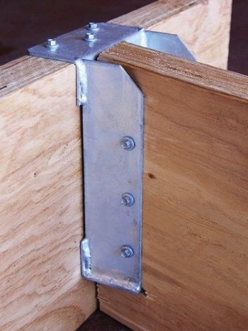
Pryda Hangers &
Truss Boots Guide
                TABLE OF CONTENTS

GENERAL NOTES                                                                 4
Useful Notes and Definitions for effective reading of this guide

BEAM HANGERS                                                                  5
Heavy brackets for large size beams

I-JOIST HANGERS
Top mount and face mount hangers for timber I-joists                          9

LVSIA – Angle brackets
                                                                              14
Brackets used as either angle cleat or angle seat

FRAMING BRACKETS
                                                                              15
Brackets for beam to beam connections

JOIST HANGERS (HEAVY DUTY)                                                    18
Brackets for heavy beam to beam or beam connections
Joist Hangers- Split                                                          19

TRUSS BOOTS – MULTI FIX
                                                                              20
For Truss to Truss Connections with option for fixing with bolts and screws

TRUSS BOOTS – HEAVY DUTY
                                                                              25
Bolted Steel Brackets for Heavy Roof Truss to Truss Connections

BOLTS KITS FOR TRUSS BOOTS
                                                                              29
Kits of bolts, nuts and washers for fixing truss boots

HIP SUPPORT BRACKETS                                                          30
Brackets to connect hip trusses to girders

                 Product Information Updates
 Information contained in this product guide is subject to change.
    The latest updates are available from www.pryda.com.au.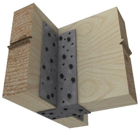
PRYDA TIMBER CONNECTORS
                              Hangers & Truss Boots Guide
                                                                      Note: Category 1 joints are defined in Table 2.2
GENERAL NOTES                                                         AS1720.1:2010 as structural joints for houses for which
                                                                      failure would be unlikely to affect an area of 25 sqm.
Timber Joint Groups
Joint groups for some common timber are tabulated                     Fastener Usage Summary
below.                                                                Following is a summary of the common nails, screws
For further information refer Table H2.3 and H2.4 in Australian       and bolts used in hangers and truss boot fixing. Read
Standards AS1720.1:2010 –– Timber Structures Part 1.                  the relevant page in this guide for a detailed
    Timbers                     Strength Group       Joint Group      specification for the respective hanger or truss boot.
                                Dry     Green        Dry Green

                                                                                                                              Pryda WTF12-35
    Oregon (Douglas fir) –       SD5        S5       JD4    J4

                                                                                                          Connector Nails
                                                                                       Connector Nails

                                                                                                                                                 M12 Bolts with

                                                                                                                                                                    M16 Bolts with
                                                                                                                                                 washers (Note 3)

                                                                                                                                                                    washers (Note 4)
                                                                                        (35 x 3.15 dia)

                                                                                                           (40 x 3.75 dia)
                                                                                        Pryda Timber

                                                                                                           Pryda Timber

                                                                                                                               screws (Note 2)
    America
    Oregon from elsewhere        SD6        S6       JD5    J5
    Radiata pine, heart-         SD6       NA        JD4    NA
    excluded
    Radiata pine, heart-in       SD6       NA        JD5    NA
    Slash pine                   SD5        S5       JD3    J3             I joist
                                                                          Hangers                              Y             Y(Note 1)
    Ash type hardwoods           SD4        S4       JD3    J3
    from Vic, NSW highlands                                               Framing
    & Tas                                                                 Brackets          Y                                     Y
    Non-Ash type                 SD3        S3       JD2    J2
    hardwoods from Qld &                                                  HD Joist
                                                                          Hangers           Y                                     Y
    NSW
Note on Engineered Timbers: Most standard LVLs are assigned                LVSIA
a JD4 joint group (SD6 strength group), and some JD3. Seek                  and                                                   Y
advice from the relevant LVL manufacturer for confirmation                  HSB
                                                                           Truss
                                                                           Boots                                                  Y                  Y                  Y
Material Thickness
All material thicknesses referred to in this guide are                       HD
the total coated thickness. This includes the zinc                         Truss                               Y(Note 1)               Y
                                                                           Boots
coating thickness, which is typically around 0.04mm                   Notes:
for Z275 steel.                                                           (1) Permitted for use only in face mounted (LF) i-joist hangers
                                                                               as an alternative to nails. Also used for fixing TBHD75/T
                                                                               or TBHD75 heavy duty truss boots.
Design Load Cases                                                         (2) Screws may be either WTF12-35 or WTF12-65.
Following is a description of the combined load cases                     (3) M12 bolts refer to OBS12/65 or OBS12/100 set screws or
                                                                               OBM12/150 or OBM12/180 hex-head bolts used in
adopted in this design guide. These load cases are in
                                                                               conjunction with OW12/56S washers.
compliance with AS/NZS1170.0:2002 – Structural                            (4) M16 bolts refer to OBS16/110 set screws or OBM16/150
design actions Part 0:General principles                                       or OBM16/180 hex-head bolts used in conjunction with
                                                                               OW16/63S washers. Refer page 30 for bolt specification
                                                                               and information on bolt kits.
      Load Case                        Description
                           Permanent Action (or Dead Load)
                                                                      Machine Driven Nail Use
          1.35G            only                                       For Framing Brackets and HD joist hangers, 50 x
                           Permanent and Roof Imposed                 2.87mm Paslode Impulse nails may be used in lieu of
      1.2G+1.5Qr           Actions (or Dead & Roof Live)              hand hammered Pryda Connector nails (35 x 3.15
                                                                      dia), provided the nails are fixed in to a minimum
                           Permanent and Floor Imposed
      1.2G+1.5Qf                                                      50mm timber. No capacity reduction is required.
                           Actions (or Dead & Floor Live)
                                                                      However, extreme care must be taken when locating
                           Permanent and Wind down Actions
        1.2G+Wd            (or Dead & Wind down)
                                                                      these nails, to ensure the hole pattern is followed.
                                                                      Given the prevailing installation practices, machine
      Wind Uplift          Permanent and Wind Up Actions (or          driven nails must be avoided if the right tool or the right
     (0.9G – Wup)          Dead & Wind up)                            operator skill-set is not available. Refer related pages
                                                                      for more details.
Design Loads & Capacities                                             For i-joist hangers, use of machine driven nails would
The tabulated capacities are for Category 1 joints. For               result in a loss of design capacity and therefore best
all other joints, reduce design capacities by using the               avoided. Contact Pryda office for advice.
following factors:                                                    Fixing into steel supporting structure
• Category 2 Joints:           0.94                                   Pryda products can be fixed into steel using Buildex
• Category 3 Joints:           0.88                                   TeksTM screws or similar. Design capacities can be
                                                                      obtained at request from a Pryda Design Office.

4                                                           PRYDA HANGERS & TRUSS BOOTS GUIDE – SEPTEMBER 2016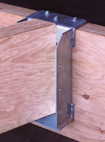
PRYDA TIMBER CONNECTORS
Hangers & Truss Boots Guide
BEAM HANGERS
Heavy Brackets for Large Size Beams & Specifications
double I-joists or floor trusses Pryda Beam Hangers are manufactured out of
G250, 3mm thick steel and are hot dipped galvanized
to a minimum 300 gsm.
Dimensions
Dimensions of Pryda Beam Hangers are shown
below.
Hanger Dimensions (mm)
Code D W BL1 BL2
BB180 186 77 75 65
Beam Hanger for Beams Beam Hanger for BB300 306 77 75 65
I-Joists BBT180240 240 180 75 65
BBT180300 300 180 75 65
Description
Pryda Beam Hangers are heavy duty welded Note; Refer page 7 for detailed information on
hangers for connection of large size beams or I-joists, BBT125240.
available in three thicknesses of 77, 125 and 180 mm, 200 BL1 BL2
to wide timber beams (min. 75 mm thick) or masonry Welded
Holes on Welded joint.
joint
walls. Refer page 7 for information on the 125mm BB45240 75
& BB75240 Two holes
Holes for for
hanger, developed to allow skew connection of beams 3.75mm
between 30 and 60 deg. for fixing to 3.75 mm
diam. nails
masonry nails- two
H per leg.
each leg
Features Coach screw
Coach screw
holes Hole
Holesforfor
Pryda Beam Hangers are: holesare
areoff-set
offset 10
M10mm diam.
coach
to to
avoid clash.
avoid clash
easy to install with a small number of coach coach
screw screw,
per
of screws leg. per leg
one
screws or nails onto timber or with masonry in beam
anchors onto masonry or concrete W
an economical means of forming these connections Holesfor
for 3.75mm diam. nails.
Holes 3.75 mm nails
ideal for supporting heavily loaded beams on fire
rated brick walls, eliminating the need for a girder 80 Holes
Holesfor
for 10mm diam.
40 10 mmscrews
coach diam. .
truss or false wall to support the beams
coach screws
180mm wide hangers support double I-joists or
double 90mm floor/rafter trusses. PLAN VIEW
Supporting member
The supporting beam, timber, masonry or concrete Details of BB180 and BB300
wall must be assessed for adequacy before use.
Holes
Holes (175mm
for Fixing apart)
to Support 75
Timber Supports - The supporting beam or wall plate for fixing coach screws
must be a min. 75mm thick. Single or multiple of 35/45 to support.
mm laminates are not suitable as it would result in
coach screws being too close to the edge. If a timber
framed wall is used, the top plates must be double Note: The top
flange is 250mm 75
laminated to ensure adequate penetration of coach wide
screws.
D
Welded Joint
Masonry Supports - The crushing strength of the
masonry must be assessed by an engineer prior to
use. Holes each side
Holes for nail
Each Side for
fixing to Nail
bottom chord
Fixing of I-
to Bottom
joist. Chord of i-joist
Supply
Beam Hangers are supplied individually. 65
W
Details of BBT180240 and BBT180300
5 PRYDA HANGERS & TRUSS BOOTS GUIDE – SEPTEMBER 2016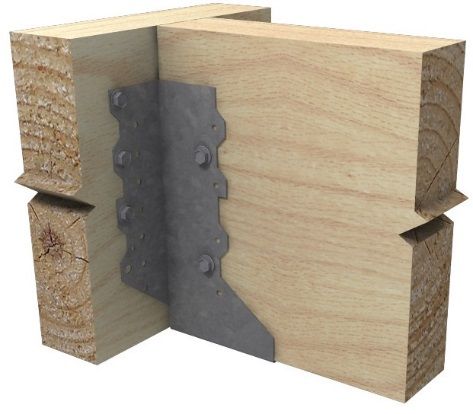
PRYDA TIMBER CONNECTORS
                         Hangers & Truss Boots Guide

    Installation
                                                                 Design Capacities: Downward loads
    Fixing to Supporting Member                                  Design Permanent load capacities (1.35G) for Pryda
    Before use, the minimum requirements of the                  Beam Hangers are tabulated below:
    supporting member must be assessed as described in
    the previous page.
                                                                      Beam                     Strength Group
                                                                    Thickness             Capacity for 1.35G load case
    Timber supports:
                                                                      (mm)                  SD6                SD4
    Use M10x100 mm coach screws and 75x3.75 mm
    galvanised flat head nails or a combination of both                 75                  22.0               25.0
    types of fasteners.                                                180                  25.0               25.0
                                                                 Notes:
    Concrete or masonry supports:                                    1.     SD6 (applicable to MGP and LVL) is the strength
    Use M10 Heavy Duty anchor, Ramset Chemical                              group used in most common applications. Refer
    Anchors or Ramset Anchorscrews.                                         General Notes in page 3 for information on strength
    Consult RamsetReid for further information.                             groups of sawn and engineered timber

                                                                     2.     For live loads, increase the above values by 20%
Supporting beam of min. 75mmbeam
                   Supporting thick                                         for floors (1.2G+1.5Qf) and 35% for roofs
                                                                            (1.2G+1.5Qr).
             Two M10x75 mm
2/M10x100 mm coach screws
               coach screws
                                                                     3.     The maximum recommended hanger capacity is
  2/75 x 3.75mm  nails
          2@ 75x3.75                                                        given as 25.0 kN (permanent load), restricted by
          mm nails                                                          non-availability of test data for higher values.

                                                                 Design Capacities: Wind Uplift
                                                                 The uplift capacity is limited by the lower of two
                                                                 M10x100 coach screws in withdrawal (supporting
                                                 Supported
                                                 Supported       beam) and two M10x50 coach screws or four nails in
                                                 beam            shear (supported beam or joist).
                                                  beam

                                                                 Below uplift capacities apply only to BB180 and
                                   Pryda Beam Hanger             BB300 hangers. For BBT hangers, a nominal uplift
                                    BB180 or BB300
                                                                 capacity of 1.5 kN can be achieved from the nail fixed
           Installation on Timber Support Beam                   into the bottom chord of each truss (2/90) or bottom
                                                                 flange of each i-joist.
    Fixing to Supported Member
    The supported member must be placed as tightly as            Coach screw fixing to supported beam
    possible against the face of the supporting beam. A
                                                                  Beam           Fixing to              Joint Group
    maximum gap of 3mm is permitted without impeding                            supported
                                                                  (mm)                         JD5     JD4     JD3       JD2
    on the design capacities. A larger gap would result in                         beam
    a rotation of the supported beam under downward
                                                                              2/M10x50 mm
    loads and also could compromise on end distance               75 Min.                      8.2     11.1     14.5     15.4
                                                                              coach screws
    requirements of nails resulting in reduced uplift
    capacities. Seek advice from a Pryda Engineer
    regarding treatment of large gaps.                           Nail fixing to supported beam
                                                                  Beam           Fixing to              Joint Group
    BB Series Hangers                                             (mm)          supported      JD5     JD4     JD3       JD2
                                                                                   beam
    Fix BB series hangers to supported timber beams with
    one M10x50 mm coach screw each side. As an                                4/40x3.75 mm
                                                                  75 min                       4.3     5.2      7.2       9.2
    alternative in low wind demand applications, drive two                         nails
    40x3.75 mm Pryda Timber Connector nails from
    each side.                                                   Notes:
                                                                     1.     The values in the above tables apply directly for
                                                                            Category 1 joints. Refer general Notes in page 4
    BBT Series Hangers                                                      for advice on reduced values for Category 2 and
    Fix BBT series hangers to timber I-joists or trusses                    Category 3 joints.
    with 35x3.15 mm Pryda Timber Connector Nails,
    one each side and one underneath each of the two                 2.     For bearing and uplift capacities of concrete or
    i-joists or trusses, ie: four nails per hanger                          masonry walls, consult a structural engineer. The
                                                                            adequacy of these walls must be assessed before
                                                                            use.

   6
    7                                                  PRYDA HANGERS & TRUSS BOOTS GUIDE – SEPTEMBER 2016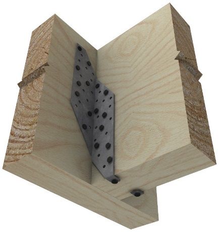
PRYDA TIMBER CONNECTORS
                         Hangers & Truss Boots Guide

BBT125240 BEAM HANGERS                                    Features
Heavy Brackets for Large Strutting Beams
                                                          Pryda BBT125240 Beam Hanger is:
                                                              easy to install with Type 17 screws
                                                              an economical means of forming these
                                                              connections
                                                              provides superior uplift resistance compared to
                                                              other conventional fixings
                                                              suitable to use with a large range of beam sizes
                                                              and connection angles (splays)

                                                          Supply
                                                           Code:                          BBT125240
                                                           Brackets per carton:           8
                                                           Screws per Bracket:            14
                                                           Screw Type:                    Pryda WTF12-35
                                                                                          screws (No. 12 X 35
                                                                                          Type 17) hex-head
            BBT125240
           Beam Hanger                                    Dimensions
                                                          Dimensions of this Beam Hanger is shown below
Description
Pryda BBT125240 Beam Hanger is a heavy duty               Design Capacities
welded hanger for connection of large sized strutting     The following capacity assumes that a minimum JD4
beams placed at angles between 30 and 60 deg, to          joint group is available at the connection.
timber beams or masonry walls. This bracket is
commonly adopted in Western Australia.
                                                                 Load Direction                  Capacity (kN)
Specifications
                                                           DOWNWARD                                    15.0
This Beam Hanger is manufactured from G300, 3mm
thick steel and are hot dipped galvanized to a min.
300 gsm.                                                   UPLIFT (light fixing)                        4.0

                 65                                        UPLIFT (medium fixing)                      10.0

                                                           UPLIFT (heavy fixing)                       20.0

                                                           Note: refer next page for details of different
                                                           fixing methods

                                   45

240
      ll

                              65                                                In application

7                                               PRYDA HANGERS & TRUSS BOOTS GUIDE – SEPTEMBER 2016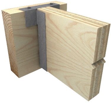
PRYDA TIMBER CONNECTORS
                 Hangers & Truss Boots Guide

BBT125240 BEAM HANGERS ….
    Fixing Methods
                                                              Light Fixing:

                                                              Supporting Beam:
                                                              3 screws on top

                                                              Supported Beam:
                                                              2 screws from bottom

                                                             Medium Fixing:

                                                             Supporting Beam:
                                                             3 screws on top and
                                                             3 screws from side

                                                             Supported Beam:
                                                             3 screws from side
                                                             2 screws from bottom

                                                              Heavy Fixing:

                                                              Medium Fixing in
                                                              combination with a
                                                              Cyclonic Strap.

7                             PRYDA HANGERS & TRUSS BOOTS GUIDE – SEPTEMBER 2016
8
PRYDA TIMBER CONNECTORS
                       Hangers & Truss Boots Guide

                                                                Bracket Types:
I-JOIST HANGERS
Face mount and top mount hangers for                            Pryda I-Joist Hanger types are illustrated below:
timber I-joists
                                                         Holes on side
                                                         flange are
Features                                                 available with
                                                         some LF
                                                                                                                       D
                                                         brackets

                                                                                        H
                                                                                                                   H
Pryda I-Joist Hangers have features as follows:
   Ideally suited to support modern timber I-Joists.
   Use of full depth hangers provides torsional restraint                 W
   to the I-joist.                                                                B                W       B
   There is provision for a screw through the hanger into                  LF Type                      LT Type
   the bottom of the bottom flange to minimize                            Face Mount                   Top Mount
   squeaking. A hole towards the bottom of each side
   flange is also available for fixing into bottom flange to
   further reduce the effect of squeaking.

Description
LT and LF types hangers are specifically designed for
use with proprietary I-Joists such as Carter Holt Harvey
hyJOIST, Tillings SmartFrame I-joist, Wesbeam e-joist
and LP I joist. Refer guide on page 11.

LT type are for top fixing and LF for face fixing. LFVS are
variable slope and skew. LFSL and LFSR are 45o degree
skewed, left and right respectively. LVSIA type is a
variable skew angle.                                                    LFVS Type                  LFSL/SR Type
                                                                   Variable Slope & Skew       45 deg Skewed Hanger
Specification
Dimensions are tabulated on the next page. All hangers
are manufactured from G300 Z275 galvanised steel in
1.2 mm thickness, except for:
LFSL/SR                                  - 2.0 mm
LF220/105, LF300/105, LT240/105          - 1.6 mm
LT300/105, LT356/121                     - 2.6 mm
LVSIA (G250, hot dip galv)               - 5 mm

Packaging
All products are packaged in quantities of 25 per carton                                LVSIA Type
except for some of the largest hangers and LVSIA which                                 Angle Bracket
are sold 10 per carton. See the Price List for details.
                                                                Dimensions H, B and W are tabulated in the Dimension
Details of the available range of Pryda I-Joist Hangers         tables following.
are tabulated in the following. ‘Double’ I-Joist Hangers
are for support of two I-Joists, side by side or a single 90    Note: Some LF hangers have holes on the side flanges
or 120 mm wide I-Joist.                                         as well. For example: LF235/90 (3 holes each), LF
                                                                290/90 (4 holes each) and LF350/90 (5 holes on each
                                                                side flange).

9                                                    PRYDA HANGERS & TRUSS BOOTS GUIDE – SEPTEMBER 2016
PRYDA TIMBER CONNECTORS
Hangers & Truss Boots Guide
Hanger range and Dimensions LT240/90 240 90 50 40 4 6
Illustrations in previous page give reference to LT300/90 300 90 50 40 4 6
dimensions H, W, B and D. LT360/90 360 90 50 40 4 6
LT400/90 400 90 50 40 4 6
Face Mount LT240/105 240 105 50 40 4 6
Product Face Nail LT300/105 300 105 50 40 4 6
H (mm) W (mm) B (mm)
Code Holes LT240/140 240 140 50 40 4 6
LF235/40 237 41 50 10 LT300/140 300 140 50 40 4 6
LF297/40 296 41 50 12
LF190/45 189 46 50 8
LF240/45 235 46 50 10
Variable Slope & Skew, Face Mount
Face Nail
LF300/45 296 46 50 12 Product Code H (mm) W (mm) B (mm)
Holes
LF235/50 231 52 50 10 LF275/60SL 275 60 64 16
LF297/50 297 52 50 12
LF275/60SR 275 60 64 16
LF340/60 342 60 50 14 LF224/90VS 224 90 70 14
LF200/65 200 65 50 8
LF235/65 235 65 50 10 Fixing Requirement
LF290/65 290 65 50 12
1. Use only 40x3.75 mm galvanised Pryda Timber Connector
LF340/65 340 65 50 14 Nails, Pryda product code OSNIB/1 or OSNIB/5.
LF235/70 232 70 50 10 2. For fixing the joist to the hanger seat, use No. 6 x 30 mm bugle-
LF290/70 288 70 50 12 head or wafer-head timber screws.
LF400/70 400 70 50 16 3. All nail holes are to be filled with the specified nails to achieve
LF235/90 235 90 50 10 published hanger capacity.
LF290/90 290 90 50 12
LF350/90
Installation
350 90 50 14
To achieve the specified design loads, Pryda I-Joist Hangers must
LF220/105 220 105 50 8 be correctly installed as specified in the following sections:
LF235/120 235 120 50 10
LF290/130 290 130 50 12 Refer to l-joist manufacturers’ instruction manuals for span table
selection and other details for on-site installation of their respective
LF235/140 235 140 50 10
systems.
LF290/140 235 140 50 12
LF235/180 235 180 50 10 Installation of Face Mount Hangers
Top Mount Max. Gap 3mm Resist Lateral Movement
Product H W B D Face Top 10mm Min
Code Nail Nail
mm mm mm mm Holes Holes Top
TopFlange
flangeofof
i-j i-joist
LT240/40 240 40 50 40 4 6 Restrained
restrained
LT300/40 300 40 50 40 4 6
LT300/47 300 47 50 40 4 6
LT200/50 200 50 50 40 4 6
LT240/50 241 50 50 40 4 6
LT240/52 240 52 50 40 4 6
LT300/52 302 52 50 40 4 6 i-joist web
Note: Use the
LT360/60 246 60 50 40 4 6 recommended screw
i-joist chord
LT240/65 240 65 50 40 4 6 to seat the I-Joist into
LT245/65 245 63 50 40 4 6 the hanger properly to
LT302/65
help reduce squeaks.
302 65 50 40 4 6
LT360/65 356 65 50 40 4 6
LT240/70 240 70 50 40 4 6 i-joist hanger
30x6 gauge bugle-head or
LT300/70 300 70 50 40 4 6 wafer-head timber screws
10 PRYDA HANGERS & TRUSS BOOTS GUIDE – SEPTEMBER 2016PRYDA TIMBER CONNECTORS
Hangers & Truss Boots Guide
Installation of Top Mount Hangers
3 mm maximum
clearance
Fix a tight
fitting packer to
steel beam to
prevent
Minimum 3 mm, bracket
max. 6 mm space
to eliminate contact rotation
between hanger 30x6 gauge bugle-head or
and steel which
may cause squeaks wafer-head timber screws
Note: Use the recommended screw to seat the I-Joist into the hanger properly to help minimize squeaks. Alternatively, if nails
are used from sides (holes available with some LT brackets), ensure they are adopted to avoid squeaks from nails coming in
contact with the hanger’s seat. Packers will be required as noted if the hanger is shorter than the supporting beam.
Installation – LVSIA
Fix top flange to support Installation- Variable Skew Angles
using 2/75 x 3.05mm nails LVSIA variable skew angles are installed as shown in the
following diagram, ie:
1. Notch the I-joist at ends (if necessary) to achieve flush fitting
the LVSIA.
2. Locate the angle with the 75 mm leg vertical and its mid-
length at the middle of the required end location of the I-joist.
Vertical leg of LVSIA Fix the angle to the supporting beam, waling plate or ledger
Supporting
fixed to supporting with 6/ Pryda WTF12-35 screws (No. 12x35 mm Type 17
beam
beam using hex head). Design capacities and other product information
6/WTF12-35 screws are given in page 15.
3. Locate the I-joist on the angle and fix it up through the bottom
of angle with 1/ No. 10 x 30 mm countersunk or bugle head
Type 17 screw.
4. Nail the I-joist top chord to the support with 2/75x3.05 mm
nails.
Fix horizontal leg of LVSIA to
i-joist using 1/No.10x30 Type 17 Notch bottom flange of i-joists to
counter-sunk screw. suit if flush finish is required
Installation – Common Problems
Poor or incorrect installation can lead to serious problems. Common problems are illustrated opposite:
If the top plate is too narrow it Spreading hanger legs will
may cause: push the joist up which may
1. Hanger Deformation. cause un-even floors,
2. Nail pull-out or squeaky floors and joist Joist is not seated
shear. rotation. properly in to the
3. Supporting beam hanger. This may
deformation cause nail pull-out.
11 PRYDA HANGERS & TRUSS BOOTS GUIDE – SEPTEMBER 2016PRYDA TIMBER CONNECTORS
Hangers & Truss Boots Guide
Design Capacities
Tabulated below are design capacities for Pryda I-joist Variable Slope & Skew Hangers
Hangers based on the specified number of nails shown. “Face Typically used to support I-joists used as roof rafters.
nails” are driven into the face of the supporting beam, “Top Design Capacity, ФNj (kN), for
nails” into the top of the supporting beams and “Joist nails” Supporting Beam with JD5 or
into the supported member. Hanger Code
Face Joist higher Joint Group for Load Case
Nails Nails
Wind
General Notes 1.35G 1.2G+1.5Qr
Uplift
1. For joints on primary beams in structures other than
LF224/90VS 14 12 4.0 6.4 4.5
houses, see General Notes on page 4 for information.
Notes:
2. Use only Pryda 40x3.75mm or 35x3.75 mm galvanised 1. Most of these brackets are suitable for applications where
Pryda Timber Connector Nails, for all LF and LT the supported member (eg: rafter) is placed at angles
brackets. Pryda WTF12-35 screws (No.12x35 mm Type between 45 deg and 90 deg to the supporting member (eg:
17 hex head) may be used as an alternative for LF roof beam). However, LF224/90VS is only suitable for
brackets only. angles of 22.5 deg from either side of the perpendicular.
2. These brackets are not suitable for floor joists.
Face Mounted Hangers 3. Where these hangers are fixed to a 35 mm thick supporting
With a minimum of eight face nails, these hangers can carry member, use the 35x3.75 mm nails and multiply design
the design residential floor loads (1.5 kPa live) for joists up to capacities by 0.88.
5.9 m span at 600 mm spacing or 7.9 m span at 450 mm
spacing, provided that the timber supporting beams has a joint
group of JD4 or better. Skewed Hangers
Face 1.2G + 1.5Qf (Dead & Floor Typically used to support I-joists used in floors at 45o to the
supporting beam.
Nails Live) Design Capacity, ФNj (kN)
Hanger Codes (screws) for Supporting Beam Design Capacity, ФNj (kN), for
Face Joist
Supporting Beam with JD5 or higher
see with Joint Group Hanger Code Nails Nails Joint Group for Load Case
Note 2 (see Note 1)
1.2G+1.5Qf (Dead & Floor Live)
JD5 JD4 JD3
LF215/90SL/R
All LF190/.. and 8 16 10 5.4
5.2 6.2 8.7 LF275/60SL/R
LF220/.. (6)
Note: Where these hangers are fixed to a 35 mm thick supporting
10 member, use the 35x3.75 mm nails and multiply design capacities by
LF 235/.., LF240/.. 6.4 7.8 10.9
(6) 0.88.
All LF290/.. LF297/.. 12
7.7 9.3 13.1 Variable Skew Angles
LF300/.. (8)
Used to support I-joists at an angle other than 90o to the
All LF340/.. 14 support, LVSIA design capacities are:
8.8 10.9 14.2
LF350/.., LF356/.. (8) 1.2G + 1.5Qf (Dead & Floor live)
Fixing in to
Design Capacity, ФNj (kN), for
16 supporting Screw
LF400/70 10.4 12.4 17.4 Supporting Beam with Joint Group
(10) member using Length
Notes: Pryda WTF12-35 (mm) JD5 JD4 JD3
(1) Where these hangers are fixed to a 35 mm thick supporting screws
beam, use 35x3.75 mm nails and multiply design capacities
by 0.88.
4 screws 35 3.9 5.5 7.8
(2) The minimum no. of Pryda WTF12-35 screws required as
an alternative fixing is given in brackets.
6 screws 35 5.8 8.2 11.5
Top Mounted Hangers
Based on the below design capacities, top mounted brackets Notes:
are suitable for joist spans of max. 5.6m (JD5), 6.6m (JD4) or
• For joints on primary beams in structures other than
7.0m (JD3) in domestic floor applications (1.5kPa @ 600 houses, see General Notes on page 4 for information.
spacing)
• Capacities of LVSIA in other applications are given in
Top Nails 1.2G + 1.5Qf (Dead & Floor Live) page 14.
Hanger
(incl. both Design Capacity, ФNj (kN), for • Fixing into joist - An additional No.10x30 Type 17 counter-
Code
top mount Supporting Beam with Joint Group sunk screw is required on horizontal leg.
tab) JD5 JD4 JD3 • The capacities may be increased by 15% if 40mm screw
lengths are used in to 45mm or thicker supporting beam.
All LT series 6 4.8 5.7 6.1
Note: 4 nail (2 nails on each tab) fixing may be used at reduced
capacities of 4.0 (JD5), 4.7 (JD4), 5.1 (JD3).
13 PRYDA HANGERS & TRUSS BOOTS GUIDE – SEPTEMBER 2016PRYDA TIMBER CONNECTORS
Hangers & Truss Boots Guide
I-Joist Hanger Cross Reference Guide
The recommended size of Pryda I-Joist Hangers for support of proprietary I-joists in house floors is as follows:
Double
I-joist Face Mount Top Mount Variable Slope Variable Skew Variable Skew Double I-joist I-joist
I-joist
Size Hanger Hanger & Skew Rafter Hanger Left Hanger Right Hanger Code Hanger
Code
(mm) Code Code Hanger Code Code Code Face Mount Code
Top Mount
Carter Holt Harvey hyJOIST
HJ200-45 200x45 LF190/45 LT200/45 LVSIA LVSIA JHH100* N/A
HJ240-45 240x45 LF240/45 LT240/45 LVSIA LVSIA JHH100* N/A
HJ300-45 300x45 LF300/45 LT300/47 LVSIA LVSIA LF220/105* N/A
HJ240-63 240x63 LF235/65 LT240/65 LVSIA LVSIA N/A N/A
HJ300-63 300x63 LF290/65 LT302/65 LVSIA LVSIA LF290/130 N/A
HJ360-63 360x63 LF340/65 LT360/65 LVSIA LVSIA LF290/130* N/A
HJ240-90 240x90 LF235/90 LT240/90 LF224/90VS* LF215/90SL* LF215/90SR* LF235/180 BBT180240
HJ300-90 300x90 LF290/90 LT300/90 LF224/90VS* LF215/90SL* LF215/90SR* LF235/180* BBT180300
HJ360-90 360x90 LF350/90 LT360/90 LF224/90VS* LF215/90SL* LF215/90SR* LF235/180* BBT180360
HJ400-90 400x90 LF350/90 LT400/90 LF224/90VS* LF215/90SL* LF215/90SR* LF235/180* N/A
Tillings SmartFrame Joist
SJ24040 240x40 LF235/40 LT240/40 N/A LVSIA LVSIA N/A N/A
SJ30040 300x40 LF297/40 LT300/40 N/A LVSIA LVSIA N/A N/A
SJ20044 200x44 LF190/45 LT200/45 LVSIA LVSIA LF190/90 NA
SJ24051 240x51 LF235/50 LT240/52 N/A LVSIA LVSIA LF220/105 LT240/105
SJ30051 300x50 LF297/50 LT300/52 N/A LVSIA LVSIA LF220/105* LT300/105
SJ36058 360x58 LF340/60 LT360/60 LF275/60SL* LF275/60SR* LF235/120* LT356/121
SJ24070 240x70 LF235/70 LT240/70 N/A LVSIA LVSIA LF235/140 LT240/140
SJ30070 300x70 LF290/70 LT300/70 N/A LVSIA LVSIA LF290/140 LT300/140
SJ24090 240x90 LF235/90 LT240/90 LF224/90VS* LF215/90SL* LF215/90SR* LF235/180 BBT180240
SJ30090 300x90 LF290/90 LT300/90 LF224/90VS* LF215/90SL* LF215/90SR* LF235/180* BBT180300
SJ36090 360x90 LF350/90 LT360/90* LF224/90VS* LF215/90SL* LF215/90SR* LF235/180* BBT180360
SJ40090 400x90 LF350/90* LT400/90 LF224/90VS* LF215/90SL* LF215/90SR* LF235/180* NA
Wesbeam e-joist
EJ20045 200x45 LF190/45 LT200/45 LVSIA LVSIA JHH100* NA
EJ24045 240x45 LF240/45 LT240/45 LVSIA LVSIA JHH100* NA
EJ24545 245x45 LF240/45 LVSIA LVSIA JHH100* NA
EJ24051 240x51 LF235/50 LT240/52 N/A LVSIA LVSIA LF220/105 LT240/105
EJ24090 240x90 LF235/90 LT240/90 LF224/90VS* LF215/90SL* LF215/90SR* LF235/180 BBT180240
EJ30045 300x45 LF300/45 LT300/47 LVSIA LVSIA LF220/105* NA
EJ30051 300x51 LF297/50 LT300/52 N/A LVSIA LVSIA LF220/105* LT300/105
EJ30090 300x90 LF290/90 LT300/90 LF224/90VS* LF215/90SL* LF215/90SR* BBT180/300 BBT180300
EJ24563 245x63 LF235/65 LT245/65 LVSIA LVSIA N/A N/A
EJ36063 360x63 LF340/65 LT360/65 LVSIA LVSIA LF290/130* N/A
EJ36090 360x90 LF350/90 LT360/90 LF224/90VS* LF215/90SL* LF215/90SR* LF235/180* BBT180360
EJ40090 400x90 LF350/90 * LT400/90 LF224/90VS* LF215/90SL* LF215/90SR* LF235/180* N/A
LP I Joist
LPI 241x70 241x70 LF235/70 LT240/70 N/A LVSIA LVSIA LF235/140 LT240/140
LPI 302x70 302x70 LF290/70 LT300/70 N/A LVSIA LVSIA LF290/140 LT300/140
LPI 406x70 406x70 LF400/70 N/A N/A LVSIA LVSIA N/A N/A
Notes: 1. For hangers marked *, web stiffeners must be installed in accordance with the I-joist manufacturers’ specification.
2. JHH100 are Heavy Duty Joist Hangers.
14 PRYDA HANGERS & TRUSS BOOTS GUIDE – SEPTEMBER 2016PRYDA TIMBER CONNECTORS
Hangers & Truss Boots Guide
LVSIA ANGLE BRACKET
(3) Screws with longer lengths are required when LVSIA
Applications brackets are fixed into multiple laminated beams. For
double laminates, use 65 long screws per flange.
LVSIA is a versatile bracket that can be used in a ‘horizontal’ (4) Increase capacities by 15% for 40mm long screws.
direction as an angle SEAT to support beams or trusses (5) If the bracket is used as a PAIR, the given capacities
coming in at any direction. This angle bracket can also be shall be increased by a factor of 2.5. Ensure the screws
used in a ‘vertical’ direction as an angle CLEAT for beam to on supporting beam are at least 30mm from end grain.
beam connections especially in situations where normal joist
hangers cannot be used. (B) ‘Horizontal’ Application as an angle SEAT
Fixings – 6/Pryda WTF12-35 screws on vertical leg and
1/No.10x30 Type 17 counter-sunk screw on horizontal leg.
Specifications
LVSIA bracket is a 150mm long x 5.0mm thick un-equal
angle of size 75 x 50 x 5.0 using G300 galvanized steel.
Design Capacities
(A) ‘Vertical’ Application as an angle CLEAT–
Bracket fixed only on one face
Fixings – 6/Pryda WTF12-35 screws on each leg.
Fixings to Fixings to
Supported Beam: Supporting Beam:
6 screws in to 6 screws in to
70mm leg 50mm leg
LOAD CAPACITIES(kN) for LVSIA as an
JOINT angle seat for given Load Cases
GROUP Wind
1.35G 1.2G+1.5Qf 1.2G+1.5Qr
Uplift
JD5 4.8 5.8 6.5 1.0
Installation: 50mm leg fixed to supporting beam
JD4 6.7 8.2 9.1 1.4
Single LVSIA as an angle cleat for given
Load Cases
JOINT JD3 9.5 11.5 12.9 1.8
GROUP Wind
1.35G 1.2G+1.5Qf 1.2G+1.5Qr
Uplift Notes:
1. The above table values may be increased by 15%
if 40mm screw lengths are used.
JD4 4.8 5.8 6.4 8.6 2. The support beam must be lateral tied to prevent
rotation.
JD3 (1) 6.7 8.0 9.0 13.3
Notes:
(1) Provide 2/No.14 x 90 Type 17 screws from the back of
supporting beam in to end-grain of supported beam to
resist twisting of supporting beam. Use longer screw
lengths if required to ensure a minimum 35mm
penetration.
(2) When the supported member used is prone to splitting
(like hardwoods-JD3), additional precautions should be
taken. These can be in the form of prebored holes or
provision of anti-split nailplates at ends of the
supported beam.
15 PRYDA HANGERS & TRUSS BOOTS GUIDE – SEPTEMBER 2016PRYDA TIMBER CONNECTORS
Hangers & Truss Boots Guide
FRAMING BRACKETS AND HEAVY DUTY JOIST HANGERS
Brackets for Beam to Beam or Beam General Description
to Brickwork/Concrete Connections Pryda Framing Brackets, Split Joist Hangers and Heavy
Duty Joist Hangers have been preferred and used in Australia
and overseas for more than 30 years. They are strong, easy to
install, cost effective, well designed connectors for many timber
beam to beam and beam to concrete or masonry joints.
The wide range of these brackets provides for all common
timber sizes and for glued laminated timber beams. These
brackets have been designed to achieve high design loads at
low cost through incorporating Pryda’s extensive design
expertise and taking account of the results of laboratory testing
at Monash University in Melbourne.
Advantages
Framing Bracket for beam to beam In addition to being well designed and laboratory tested, Pryda
Connections Framing Brackets (formerly called Pryda Joist Hangers) are:
cost effective, eliminating the need for costly on-site skilled
labour to make special housing for joints etc.
easily fixed into position with Pryda Timber Connector
Nails, or self-drilling screws. These hangers have wide
flanges for ease of nailing and screwing.
Framing Bracket Size Selection
To establish a suitable Framing Bracket size, determine:
1. Joint groups are specified in AS1720.1 SAA Timber
Structures Code and in Pryda Timber Data. Groups for
some timbers commonly used in Australia are:
Timbers Joint Group
Heavy Duty Joist Hanger for Dry Green
Large Sizes, Heavy Loads North American Oregon, western Hemlock JD4 J4
Heart-excluded Radiata pine and other JD4 J4
softwoods
Pine as above – heart-in JD5
Slash pine JD3 J3
Ash type hardwoods from Victoria, NSW JD3 J3
highlands and Tasmania
Non-Ash type hardwoods from Queensland JD2 J2
and NSW
Note: The moisture content of “dry” timber must not exceed 15%.
Where beams of different joint groups are to be joined together, apply
the lower group to both. Also read General Notes.
2. Applied loads are to be calculated in accordance with
appropriate standards. These loads (reactions) can also
be obtained from Pryda Build software.
Split Joist Hanger for 3. Thickness of beam, truss or joist to be supported and
Heavy Loads supporting beam thickness. Ensure 1 or 2 mm tolerance
is considered when selecting the appropriate
Bracket/Hanger for the given beam or truss thickness. The
internal dimensions (thickness) of the bracket or hanger
are provided in this guide.
4. Fixing method: nails or screws, but not both combined.
5. Bracket/Hanger size to be selected from the design
capacity tables in this guide based on the above data.
16 PRYDA HANGERS & TRUSS BOOTS GUIDE – SEPTEMBER 2016PRYDA TIMBER CONNECTORS
Hangers & Truss Boots Guide
Description Dimensions
This section covers properties of Pryda Framing
Brackets, formerly known as Joist Hangers. Supporting beam A
Features
Pryda Framing Brackets are suitable for many joints
including:
- joist to beam - floor truss to beam
- jack to TG truss - pergola rafters to fascia
Depth of
- ceiling joist to hanger - beams to masonry
Thickness Hanger
hanger
Installation
Fix Framing Brackets to supporting beams using either Beam A
nails or screws, not both types of fasteners. thickness
Pryda Joist Bearing == 75
Bearing 75
Suitable fasteners are: Hanger
Supported except
(60 = 60 & FB65170)
for FB130
beam B on FB130
Nails: Use only 35 x 3.15 mm, galvanised Pryda Timber & FB65170
Connector Nails or 50x2.87 mm Paslode Impulse
galvanized screw hardened D head nails (Code: Code Thickness** Depth
B20573V) driven through the metal- not into the holes.
Note: The use of 50x2.87 nails should be restricted to FB3860 39 60
timber thicknesses of 50mm or more. Extreme care must FB3890 39 80
be taken when using machine driven nails (read General
Notes in page 4 for more details) FB3590 36 82
FB35120 36 116
Screws: Pryda WTF12-35 (No. 12x35 mm Type 17 hex FB35180 36 182
head screws)
FB4290 43 78
See the Design Capacities table on the following page FB42120 43 112
for the maximum number of nails or screws for each
Framing Bracket. FB42170 43 170
FB42220 43 218
Specification FB4590 46 77
Dimensions (sizes) are as shown here. All framing
brackets are manufactured from G300 Z275 galvanised FB45120 46 110
steel in 1.0 mm thickness.
FB45140 46 134
Packing FB45180 46 176
Framing Brackets are supplied in cartons as follows: FB45220 46 216
Product Codes Carton FB58120 59 104
Number
FB58170 59 170
FB: 3860^, 5060^, 3590*, 3890*, 4290, 4590*,
5090^, 35120*, 38120^, 42120, 45120*, 45 FB58220 59 210
50120^, 58120
FB65170 65 167
FB: 35140^, 38140^, 45140*, 50140^ 40
FB70200 71 194
FB: 35180, 38180^, 45180*, 42170, 50180^,
30 FB72163 72 163
58170
FB: 60130, 65170, 70200, 84200, 90200, FB84200 85 197
25
72163, 94152 FB90200 91 194
FB: 42220, 45220, 50220^, 58220 15
FB94152 94 152
Notes:
Note: FB70200, FB72163, FB90200 and FB94152 are suited
1. * Means also available as an individually barcoded to support of Pryda Longreach or Pryda Span floor trusses.
Merchant Pack, with code starting ”MPFB”
2. ^ Only available as an individually barcoded
Merchant Pack. with code starting ”MPFB”. ** Thickness here refers to the internal dimension of the
3. Available in stainless steel are: FB3590, FB3890, bracket between flanges, facilitating beam thickness.
FB4590 and FB5090- sold by piece.
17 PRYDA HANGERS & TRUSS BOOTS GUIDE – SEPTEMBER 2016PRYDA TIMBER CONNECTORS
Hangers & Truss Boots Guide
Design Capacities per Framing Bracket
1.2G+1.5Qf Wind Uplift
(Dead +Floor Live Load) Fixing to
Fixing to Supported (k1 = 1.14)
Framing Bracket Supporting Beam
Code Beam Design Capacity φNj (kN) Design Capacity φNj (kN) for Joint
for Joint Group (Beam B) Group
(Beam A)
mm
JD5 JD4 JD3 JD5 JD4 JD3 Max.
6 nails 2.9 3.4 4.8 3 nails 2.4 2.8 3.9 4.5
FB3860
2 screws 2.1 3.0 4.3 2 screws 3.5 5.0 5.0 5.0
FB3590, FB3890 8 nails 3.8 4.6 6.4 4 nails 3.2 3.7 5.3 6.0
FB4290, FB4590 4 screws 4.3 6.1 8.5 2 screws 3.5 5.0 5.0 5.0
FB35120 12 nails 5.3 6.4 8.9 6 nails 4.7 5.7 7.9 9.0
FB42120, FB45120 6 screws 6.4 9.1 12.8 4 screws 7.1 10.0 10.0 10.0
16 nails 7.0 8.4 11.7 8 nails 6.1 7.3 10.0 10.0
FB45140
6 screws 6.4 9.1 12.8 4 screws 7.1 10.0 10.0 10.0
FB58120 6 screws 6.4 9.1 12.8 4 screws 7.1 10.0 10.0 10.0
FB35180 20 nails 8.6 10.3 14.4 10 nails 7.4 8.9 12.4 15.0*
FB42170, FB45180 8 screws 8.6 12.1 15.0* 6 Screws 10.6 15.0* 15.0* 15.0*
26 nails 10.8 12.9 15.0* 12 nails 8.6 10.7 14.5 15.0*
FB42220, FB45220
10 screws 10.1 14.2 15.0* 8 Screws 14.2 15.0* 15.0* 15.0*
22 nails 9.2 11.0 15.0* 12 nails 8.6 10.7 14.5 15.0*
FB84200
8 screws 8.6 12.1 15.0* 8 screws 14.2 15.0* 15.0* 15.0*
18 nails 7.8 9.3 13.1 6 nails 4.7 5.7 7.9 9.0
FB58170
6 screws 6.4 9.1 12.8 11 nails 8.1 9.8 13.6 15.0*
FB65170
6 screws 10.6 15.0* 15.0* 15.0*
FB58220 24 nails 10.0 11.9 15.0* 12 nails 8.6 10.7 14.5 15.0*
FB70200 10 screws 10.1 14.2 15.0* 7 screws 12.3 15.0* 15.0* 15.0*
18 nails 7.8 9.4 13.0 3 nails 2.4 2.8 3.9 4.5
FB58170
6 screws 6.4 9.1 12.8 10 nails 7.4 8.9 12.4 15.0*
FB72163
6 screws 10.6 15.0* 15.0* 15.0*
26 nails 10.8 12.9 15.0* 13 nails 9.6 11.6 15.0* 15.0*
FB90200
10 screws 10.1 14.2 15.0* 8 screws 14.2 15.0* 15.0* 15.0*
18 nails 7.8 9.3 13.1 3 nails 2.4 2.8 3.9 4.5
FB94152 6 screws 6.4 9.1 12.8 10 nails 7.4 8.9 12.4 15.0*
6 screws 10.6 15.0* 15.0* 15.0*
Notes: 8. Multiple Laminated Supporting Beams: Fasteners with longer
1. Beam A = Supporting, Beam B = Supported. lengths are required when Joist Hangers are fixed into a multiple
2. The above tabulated capacities are for a minimum Beam A laminated supporting beam. For double laminates, use 65 long
thickness of 35 mm. nails or screws. Alternatively, for double or triple laminated
supporting beams, additional fixings may be provided at hanger
3. Framing Bracket capacity has been limited to 15.0 kN (shown ‘*’).
locations to laminate plies. Seek advice from the Engineer.
4. The values in the table apply directly for Category 1 joints. Refer
9. Gap between Supported and Supporting Beams: A maximum gap
General Notes in page 4 for advice on how the values should be
of 3mm is permitted without impeding on the design capacities. A
reduced for Category 2 and Category 3 joints.
larger gap would result in a rotation of the supported beam under
5. For FB58170 and FB65170 brackets, wind uplift values have been downward loads and also could compromise on end distance
reduced due to a shorter end distance on the supported beam requirements of nails resulting in reduced uplift capacities. Seek
compared to the other brackets. advice from a Pryda Engineer regarding treatment of large gaps.
6. For FB70200 to FB94152, the wind uplift 3 nails fixing option allows 10. The framing bracket shall not hang more than 10mm below the
for fixing to the chords only of I-beams or trusses. underside of Beam A, if the above table values are to be
7. Unless the top of the supported beam is provided with additional maintained. Seek advice from a Pryda engineer.
lateral restraints, the bracket must cover at least 60% of the depth 11. Capacities for the 50mm merchant pack (“MPFB50”) range are
of the supported beam. not available in the above table. Use the values for the
corresponding FB45.
18 PRYDA HANGERS & TRUSS BOOTS GUIDE – SEPTEMBER 2016PRYDA TIMBER CONNECTORS
Hangers & Truss Boots Guide
JOIST HANGERS – HEAVY DUTY Design Capacities
Design capacities per Heavy Duty Hanger are as follows:
Heavy Duty Hanger for
Large Sizes, Heavy Loads Nail Fixing – 35 x 3.15mm Pryda Timber Connector nails
Design Capacities (ΦNj) in kN
for varying hangers and Joint Groups
JHH58, JHH65, JHH75 JHH100
Load Case
30 nails to Beam A 34 nails to Beam A
18 nails* to Beam B 22 nails* to Beam B
JD5 JD4 JD3 JD5 JD4 JD3
JHH.. Hanger
1.35G 10.7 12.7 17.8 12.1 14.4 20.2
Features
Pryda Heavy Duty Joist Hangers are designed to support 1.2G + 1.5Qf 12.9 15.4 21.6 14.6 17.5 24.5
heavily loaded timber beams or two ply trusses on 1.2G + 1.5Qr 14.4 17.2 24.1 16.3 19.5 27.3
supporting timber beams or girder trusses. All have tongues 1.2G + Wd 24.4 29.0 30.0 27.6 30.0 30.0
for fixing to supports to resist twisting and rotation.
Wind Uplift 13.0 15.4 13.7* 16.1 19.2 17.1*
Specification
Steel: 1.2 mm Zincform® G300-Z275 Screw Fixing – Pryda WTF12-35 screws
Packing 10 per carton Design Capacities (ΦNj) in kN
for varying screw configuration and Joint Groups
Sizes: As below:
Option 1 Option 2
Load Case
Dimensions 12 screws to Beam A 20 screws to Beam A
8 screws to Beam B 16 screws to Beam B
167 177 202 JD5 JD4 JD3 JD5 JD4 JD3
1.35G 10.0 14.0 20.0 15.9 22.5 30.0
126 126 1.2G + 1.5Qf 12.2 17.0 24.3 19.3 27.2 30.0
140
1.2G + 1.5Qr 13.6 19.0 27.1 21.5 30.0 30.0
122 122 139 1.2G + Wd 20.1 28.0 30.0 30.0 30.0 30.0
65
58 or 65 75
51 51 100
95 Wind Uplift 14.4 20.0 28.7 26.0 30.0 30.0
51
Notes:
JHH65
JHH58 or JHH65 JHH75
JHH 75 JHH100
JHH100 1. Beam A = Supporting Beam, Beam B = Supported Beam.
Note: The internal dimension of the JHH100 hanger is only 2. Wind capacities –
95mm, specially designed to cater for 2/45 thick beams, i- The JD3 capacities (marked *) are based on 11 nails for
joists or trusses or 90mm thick floor trusses or equivalent. JHH65 and JHH75 and 14 nails for JHH100 to satisfy end
distance requirements (also see Note 3). Limiting capacity of
JHH75 (internal dimension of 75mm) is suitable for 2/35 the hangers = 30.0 kN
thick beams or trusses or 70mm thick floor trusses or 3. Supported Beam prone to Splitting - JHH brackets are not
equivalent. recommended to resist uplift loads for supported members
using timbers that are prone to splitting (like hardwoods-JD3
Installation joint group) unless additional precautions are taken. These
can be in the form of pre-bored holes or provision of anti-split
Correct installation of Pryda Heavy Duty Joist Hangers is
nailplates at ends of the supported beam.
essential to achieve the design capacities. Use only 35x3.15
mm galvanized Pryda Timber Connector Nails or 50x2.87
mm Paslode Impulse galvanized screw hardened D head 4. Multiple Laminated Supporting Beams - Fasteners with longer
nails (code B20573V). Extreme care must be taken when lengths are required when JHH brackets are fixed into a
using machine driven nails, read note on page 4 for further multiple laminated supporting beam. For double laminates,
details. Alternatively use Pryda WTF12-35 screws (No. use 65 long nails or screws. Alternatively, for double or triple
12x35 mm Type 17 hex head) laminated supporting beams, additional fixings may be
provided at hanger locations to laminate plies. Seek advice
from the Engineer.
Do not nail or screw within 30 Beam B
mm of the ends of the timber
5. The values in the table apply directly for Category 1 joints.
beams or within 6 mm of beam
Refer general Notes in page 4 for advice on how the values
edges. should be reduced for Category 2 and Category 3 joints.
Fix the tongue to the underside of
supporting beam A with: 6. Beams must be at least 140mm deep. For beams of lesser
depths, the tabulated capacities may be adjusted by a factor
• minimum 4 nails for single
equal to the ratio of the number of effective fasteners by the
laminate Beam A number of fasteners tabulated above. Unless the top of the
• minimum 3 nails into each Beam A supported beam is provided with additional lateral restraints,
laminate for multi-laminate the bracket must cover at least 60% of the depth of the
Beam A. supported beam.
19 PRYDA HANGERS & TRUSS BOOTS GUIDE – SEPTEMBER 2016PRYDA TIMBER CONNECTORS
Hangers & Truss Boots Guide
SPLIT JOIST HANGERS Design Capacities
Design capacities for a pair of Pryda Split Joist Hangers
Supporting Beam Supported Beam in houses are:
(Beam A) (Beam B) Design Capacities (ΦNj) in kN per PAIR of JHHS
for Fasteners and Joint Group
35x3.15 mm Nails Pryda WTF12-35
Screws
Load Case
16 nails per hanger 6 screws per hanger
per beam per beam
(see Note 6 for options)
JD5 JD4 JD3 JD5 JD4 JD3
1.35G 10.4 12.4 13.3 9.9 14.0 19.8
1.2G + 1.5Qf 12.6 15.0 16.1 12.0 17.0 24.0
Features 1.2G + 1.5Qr 14.1 16.8 17.9 13.4 19.0 26.8
Pryda Split Joist Hangers are: 1.2G + Wd or
23.8 28.3 29.8 19.9 28.1 39.6
Wind uplift
suitable for any practical thickness of timber beam.
Notes:
manufactured from heavy duty (1.6 mm) steel. 1.Beam A (Supporting Beam) and Beam B (Supported Beam)
must be a minimum 240mm deep to achieve above nail
Specification capacities or 200mm to achieve screw capacities. See Note 6
for further screw options.
Steel: 1.6 mm Zincform® G300-Z275
2. Wind capacities : The JD3 capacities are based on a reduced
Packing per Supplied in cartons of 10, ie. 5 right number of fasteners (for nails only) to satisfy end distance
carton hand and 5 left hand. requirements (also see Note 3).
Code & Size: Product code is JHHS. Size as below 3. Supported Beam prone to Splitting: JHHS brackets are not
recommended for supported members that are prone to
52 For full fixing,
Nail capacity,drive
16 16 splitting (like hardwoods-JD3 joint group) unless additional
Timber Connector
nails per hanger into precautions are taken. These can be in the form of pre-bored
Nails or 8G screws
the supporting beam holes or provision of anti-split nailplates at ends of the
per hanger supported beam.
and 16 nails per
into supporting
hanger into the 4. Multiple Laminated Supporting Beams - Fasteners with longer
beam
supported beam. lengths are required when JHHS brackets are fixed into a
199
For full capacity, multiple laminated supporting beam. For double laminates,
Screw fixing,16refer
Timber
belowConnector
illustrations
use 65 long nails or screws. Alternatively, for double or triple
Nails or 8G screws laminated supporting beams, additional fixings may be
30 mm min. per hanger provided at hanger locations to laminate plies. Seek advice
end distance Do not nail or screw
into supported
within 30 mm beam
of the from the Engineer.
for nails 34 ends 30
at min. mm from
of the timber 5. The values in the table apply directly for Category 1 joints.
beam end
17 62 beams Refer General Notes in page 4 for advice on how the values
Installation should be reduced for Category 2 and Category 3 joints.
Use only 35 x 3.15 mm galvanized Pryda Timber 6. Screw Fixing Options- Further to capacities given above
Connector Nails or 50x2.87 mm Paslode Impulse using 6 screws per hanger per beam, different screw
galvanized screw hardened D head nails (code B20573V) configurations may be used as illustrated below. Adjust
capacities accordingly, by using a factor (n/6) where n =
driven though the metal, not through the holes, to fix these
number of screws used per hanger per beam. Limit
connectors. Read note on machine driven nails in page 4.
maximum capacity to 40.0 kN irrespective of load case.
As an alternative, use Pryda WTF12-35 (No. 12x35 mm 7. Gap between Supported and Supporting Beams: A maximum
Type 17 hex head screws). Refer below for the required gap of 3mm is permitted without impeding on the design
number of screws and the associated design capacities. capacities. Seek advice from a Pryda engineer for treatment
of larger gaps.
For supporting beam depths between 200
and 240mm, this screw must be relocated.
SCREW
FIXING
OPTIONS
Fixing per hanger per beam - 4 screws 6 screws 8 screws 10 screws
Modified Capacity - Table Value x 0.67 Use Table Value Table Value x 1.33 Table Value x 1.67
Min. Beam Depth - 200mm 200mm 240mm 240mm
20 PRYDA HANGERS & TRUSS BOOTS GUIDE – SEPTEMBER 2016PRYDA TIMBER CONNECTORS
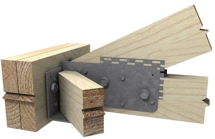
Hangers & Truss Boots Guide
TRUSS BOOTS- MULTI-FIX
Metal brackets for truss to truss Steel TBS – 1.2 mm G300 –Z275 Galvanized
connections TBJ & TB – 1.6 mm G300 –Z275 Galvanized
Packing 10 per carton
Size See dimensions following
Note: The TBJ35/T has a tongue to tie the supported truss to
the girder.
Dimensions
Dimensions of Pryda Joist Boots and Truss Boots are:
TBJ35, TBJ35/T, TBJ45
38/48 73
Bolted Truss Boots 55 55
95
95
17 15
75 103
115
TB35, TB45 TBJ70
38/48
55
Screw Fixed Truss Boots
95
Application & Features 17
Pryda Multi-Fix Truss Boots are used to connect roof 75
trusses or other roof members to supporting “girder” 50
trusses and they comprise:
Joist Boots –used for: Installation
Fix Pryda Multi-Fix Truss Boots with fasteners as
* End support of joists and beams tabulated below:
* Support of lightly loaded trusses from girder trusses
Boot Type To Supporting To Supported
Truss Boots – used for support of standard trusses. (Girder) Truss Truss
See also Pryda Heavy Duty Truss Boots. TBJ35/45, 2 M12 Bolts, or 8 1 M12 Bolt or 8
TBJ70 Screws or Bolts + Screws or Bolts +
Screws Screws
“Multi-fix” means that these connectors can be fixed with
bolts or screws, or bolts and screws together. 2 M12 Bolts, or 8 2 M12 Bolts or 12
TB35/12 Screws or Bolts + Screws or Bolts +
Screws Screws
Specification
2 M16 Bolts, or 8 2 M12 Bolts or 12
Type Product Timber Bolt Application- TB35/16, Screws or Bolts + Screws or Bolts +
Code Thick. Diam. Support of: TB45/16 Screws Screws
TBJ35 35 12 eg: at hip ends Notes:
TBJ35/T 35 12 Lightly loaded 1. M12 or ½ inch diameter must be fitted with nuts and 55
mm diameter or 50x50 mm square by 3 mm thick
TBJ45 45 12 trusses
washers. M16 or 5/8 inch diameter bolts must be fitted
TBJ70 70 12 with nuts and 65 mm diameter or 57x57 mm square by 4
mm thick washers. See Pryda Bolt Kits
TB35/12 35 12 Standard
Truss 2. Screws are Pryda WTF12-35 (No. 12x35 mm Type 17 hex
TB35/16 35 16/12 trusses
Boot head screws)
TB45/16 45 16/12
21 PRYDA HANGERS & TRUSS BOOTS GUIDE – SEPTEMBER 2016PRYDA TIMBER CONNECTORS
Hangers & Truss Boots Guide
Installation of
Pryda Multi-Fix Truss Boots Screws Only Installation:
1. If the girder truss is comprised of two or more laminates
(ie: a “double” or “triple” girder), the laminates must be
Bolts Only Installation: fixed together using one of the details specified in Fixing
1. Fit the Boot flush with the bottom of the girder bottom Details For Double or Triple Girders opposite.
chord and tack fix with two nails or screws. Drill the bolt 2. Fit the Boot flush with the bottom of the girder bottom
hole and fit the bolt with the nut and washer on the face chord and tack fix with two screws. Drive the remaining
opposite to the boot. Ensure correct bolt length and screws.
specification is used, see page 30 for information. 3. Sit the incoming member into the boot and fix it in place.
2. Sit the incoming member into the boot and fix it in place. The clearance between the end of the incoming member
The clearance between the end of the incoming member and the face of the girder truss chord should not exceed
and the face of the girder truss chord should not exceed 5 5 mm, preferably 0 mm. Drive screws into all holes.
mm, preferably tight fitting. Drill the bolt hole (TBJ and TB
types only) and fit the bolt(s) and nut(s).
3. Hammer apply anti-split Claw nailplates on the girder truss
chord on both faces and both sides of the Boot, ie: 4
nailplates of:
Chord width (mm) 90 120,140 170,190
Anti-split Plate Size 3C2 4C2 6C2
Note: Anti-split Claw nailplates are NOT required for
boots fixed with M12 bolts into timbers that are not
prone to splitting.
4. Important: The roof cladding (tiles, sheet steel etc) must
be installed only after the truss boots are fully fixed into
both the girder and supported truss, with all bolts and
washers in place. TB35 Fixing: 8/WTF12-35 screws
into supporting truss and
Anti-split nailplates (if 12/WTF12-35 screws into
necessary) on both supported truss.
faces of girder and
both sides of boot
Front View Note: that anti-split nailplates are not required for Screws
Only fixing.
Bolts & Screws Installation:
1. Install the Truss Boot and supported truss as per the Bolts
Only method.
2. Drive the screws into all screw holes.
M12 (with 50x50 square washers) or Important: The roof cladding (tiles, sheet steel etc) must
M16 (with 65 diam or 57x57 square
be installed only after the truss boots are fully fixed into
washers). Washers are required only on
the back face. both the girder and supported truss.
Back View
Side View
TB35/12 Fixing: 2/M12 bolts and
8/WTF12-35 screws into supporting truss
and 2/M12 bolts 12/WTF12-35 screws
into supported truss.
22 PRYDA HANGERS & TRUSS BOOTS GUIDE – SEPTEMBER 2016PRYDA TIMBER CONNECTORS
Hangers & Truss Boots Guide
Fixing Details For Double & Triple
Girders- Screws Only Fixing Option
Notes:
1. Nails at the Truss Boot are to be spaced 70mm (min)
DOUBLE GIRDERS apart along the grain and 40 mm (min) apart across the
2@ 35 Girder Laminations – Preferred Fixing Detail grain. They should be as close to the Truss Boot as
practical, but not further away than the depth of the
Truss Boot member.
2. Use the details for 35 mm laminates for timber thickness
between 35 and 40 mm, and the 45 mm details for timber
thickness between 41 and 50 mm.
3. All screws are to be Pryda WTF12-35 (No. 12x35 mm
65 mm Self drilling wood Type 17 hex head screws ) or Pryda WTF12-65.
screws into the girder
Alternative Fixing Detail 4. For all double and triple girder trusses, the chords (top
and bottom) and webs are to be nailed at:
Truss Boot
Timber Width Nail Rows & Maximum Spacing
Up to 100 mm 2 rows (staggered) at 500 mm
8@ 35 mm Self drilling wood screws 101 - 200 mm 2 rows (staggered) at 250 mm
+ 10@ 65x2.87 mm nails into girder 201 - 300 mm 3 rows (staggered) at 250 mm
2@ 45 Girder Laminations – Preferred Fixing Detail
Truss Boot
Nails staggered
25 mm
25 mm
65 mm Self drilling wood screws 500 mm
+ 4@ 90x3.33 mm nails into girder Timber Up to 100 mm Chords or Webs
Alternative Fixing Detail 250 mm 250 mm
Truss Boot 25 mm
25 mm
35 mm Self drilling wood screws 250 mm 250 mm 250 mm
+ 8@ 90x3.33 mm nails into girder
101 - 200 mm Chords or Webs
TRIPLE GIRDERS
3@ 35 or 3@ 45 mm Laminations – Preferred Fixing 250 mm 250 mm
Truss Boot 25 mm
250 mm 250 mm
35 mm Self drilling wood screws
+ 2@ M12 bolts with 50x50x3 mm 25 mm
square washers on timber side only 250 mm 250 mm
Alternative Fixing Detail
Truss Boot 201 -300 mm Chords or Webs
35 mm Self drilling wood screws
+ 18@ 90x3.33 mm nails:
(12 to front lamination, 6 to back lamination)
23 PRYDA HANGERS & TRUSS BOOTS GUIDE – SEPTEMBER 2016You can also read