Digital Micrograph Program To Acquire 3D ED Datasets in a Routine and Systematic Way - Johannes Gutenberg-Universität Mainz
←
→
Page content transcription
If your browser does not render page correctly, please read the page content below
Fast-ADT v3.2
              Fast & Automated Diffraction Tomography
                   Digital Micrograph Program To Acquire
                         3D ED Datasets in a Routine
                             and Systematic Way

                                 Technische Universität Darmstadt,
                               Johannes-Gutenberg Universität Mainz
                                    & Universitat de Barcelona
                                             June 2020

                                         Sergi Plana Ruiz
                                             Ute Kolb
                                     Joaquim Portillo Serra
                                      Sònia Estradé Albiol
                    Contact e-mail: sergiplana@hotmail.com; kolb@uni-mainz.de

Consider to cite the Fast-ADT publication if used in your work: “Fast-ADT: a fast and automated electron
diffraction tomography setup for structure determination and refinement”, S. Plana Ruiz, Y. Krysiak, J.
Portillo, E. Alig, S. Estradé, F. Peiró & U. Kolb. Ultramicroscopy 211 (2020) 112951.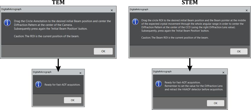
TUD, JGUM, UB 2020            Fast-ADT

Contents
1 Installation                      2

2 Parameters Setup                  3

3 Beam Settings                     4

4 Crystal Tracking File             6

5 Acquisition                       8

6 Data Formats                     10

                          1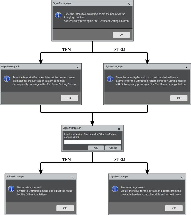
TUD, JGUM, UB 2020                                                                              Fast-ADT

1     Installation
    1. Create a folder called FastADT_Storage in C:

    2. Drag the files “greenLED.jpg” and “nonactiveLED.jpg” to the created folder.

    3. Create the“config.tx” file by running the script “CreateConfigFile.s” in Digital Micrograph. Ensure
       to change the “manu” variable to “FEI” or “JEOL” according to your TEM manufacturer, and insert
       the calibration (nm) in the “cali” parameter for an image of Digital Micrograph with a magnification
       in TEM mode around 43K. If the magnification is different than 43K modify the string “magni” inthe
       script according to your choice.

    4. Drag the “FastADT_plugin.gtk” file to the folder “Plugins” inside the “Gatan” folder at C:\Program
       Files. After re-starting Digital Micrograph, a new menu should appear with the name “Fast-ADT”
       and two sub-menus called “Acquisition” and “Stack Split”. The following GUI should appear after
       clicking on “Acquisition”.

                                                      2
TUD, JGUM, UB 2020 Fast-ADT
2 Parameters Setup
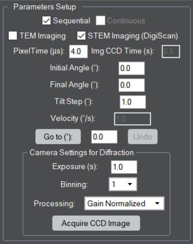
The parameters setup is the module of the GUI in which you can select all the variables related to
the acquisition of a Fast-ADT dataset. This version allows to switch between TEM or STEM imaging (if
DigiScan available) according to the preferred imaging mode selected by the user to operate the microscope.
When TEM imaging is selected, the “Img CCD Time” is enabled in which the exposure time in seconds (0.5
by default) is introduced for the acquisition of the tracking images. When STEM imaging is selected, the
“Pixel Time” in µs is enabled.
After the selection of the imaging part, the stage parameters follow. Here the initial angle, final angle
and tilt step in degrees can be set. The program limits the values down to -70◦ and up to 70◦ . If the holder is
close-by the pole pieces of the objective lens, the TEM usually blocks the further tilt and Digital Micrograph
does not force it to move forward. However, special attention has to be paid to avoid these undesired situ-
ations. The “Go to” button allows to tilt the stage to the desired tilt angle inserted in the box at its right.
The “Undo” button goes back to the last tilt angle in which the stage was before clicking the “Go to” button.
The camera settings for the acquisition of diffraction patterns follow the stage parameters. Here, the
exposure, binning and processing can be selected for the acquisition of diffraction patterns. The resulting
image with the chosen parameters can be acquired with the “Acquire CCD Image” button.
3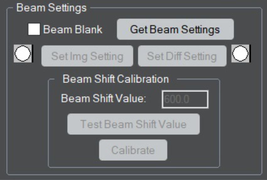
TUD, JGUM, UB 2020                                                                                   Fast-ADT

3    Beam Settings

   The beam settings are the different sizes of the beam for the acquisition of images and diffraction patterns.
By pushing the “Get Beam Settings” button, the following dialogues appear.

                                                       4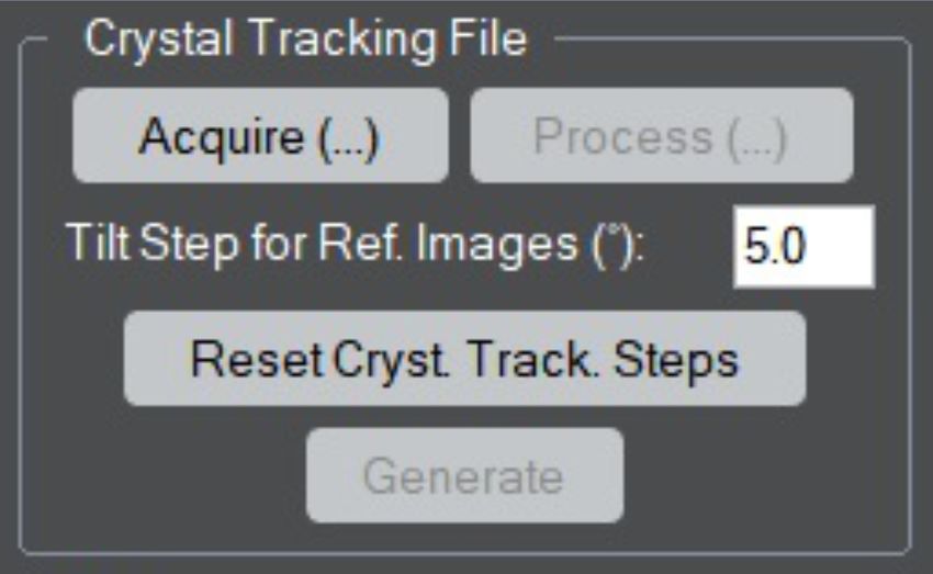
TUD, JGUM, UB 2020                                                                                    Fast-ADT

    By clicking the first time the “Get Beam Settings” button, the program tells that the beam should be
adjusted for imaging, thus it should be wide open covering the whole field-of-view for the magnification that
you are going to use for the tracking frames and centred with the beam shifts, if using TEM mode. In case
that STEM mode is used, the size of the beam is the smallest possible or, if the sample is beam sensitive,
a bit bigger while it allows the visualization of crystals when scanned. Once this is done, the button is
pressed once again to save these settings and a second dialogue box appears, which is different if you are
working in TEM or STEM. In both cases, the aim is to set the desired beam diameter for the acquisition
of the diffraction patterns. The dialogue is different in STEM because sometimes the TEM images that are
acquired with the CCD while being in the STEM mode of the microscope are not calibrated. This ensures
that the user brings the magnification to the one set during the program installation and the beam diameter
can be properly determined.

    By clicking the button a third time, the program asks for the size of the beam and after writing it down
in the dialogue box and pressing “Ok”, a final dialogue box appears that is as well different with respect to
the operation mode of the microscope (TEM or STEM). In case of TEM, the projector system is switched
to diffraction and the diffraction lens is adjusted until a focused primary beam is obtained. When the mi-
croscope is working in STEM, the diffraction lens has to be modified through an available free lens control
module of the microscope (TEMspy in FEI/Thermo Fisher microscopes), write it down and subsequently
reset the value to the default one. That is because the STEM calibrations are performed on a specific value
of the diffraction lens, and, if modified, the primary beam will be shifted while scanning the beam. In case
that the primary beam is not shifting a lot, the adjusted value can be used for the scanned imaging as well.
Otherwise, it has to be changed when the electron beam is changed to acquire scanned images or focused
diffraction patterns.

   After getting through the beam settings, the electron beam for imaging can be recalled through the
“Set Img Setting” button and for diffraction pattern acquisition by the “Set Diff Setting” button. The
small icon at the site of each button indicates which setting has been clicked or set last when it appears green.

    When the TEM mode is operated in the microscope, an extra calibration for the beam settings has to
be carried out, the “Beam Shift Calibration”. In this case, the beam has to be positioned by the beam
shifts to the centre of the CCD with the diffraction setting selected. At this point, the default 600 (a.u.)
value for the beam shift has to be tested by clicking the “Test Beam Shift Value” button. When clicked,
the program will shift the beam along the x-axis and y-axis and the user can check if this value is enough
to reach the edges of the detector but still see the whole beam. If it is too large or too low, the value
can be changed in the “Beam Shift Value” box. The live display of the camera can be used to see the
shift of the beam when applied by the program. For every shift, a information dialogue will appear that
needs to be accepted to go to the following shift. Once the good value is found, the “Calibrate” button
is pressed in order to acquire the images of the shifted beam to create the BeamShiftCalibration.txt file in
the FastADT_Storage folder. It is recommended to use the magnification that is going to be used for the
acquisition of the reference tracking images.

                                                       5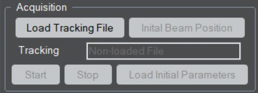
TUD, JGUM, UB 2020                                                                               Fast-ADT

4    Crystal Tracking File

    After the beam settings are selected (section 3) and the parameters for the Fast-ADT acquisition are set
(section 2), the generation of the crystal tracking file for the targeted crystal can start.

                                                     6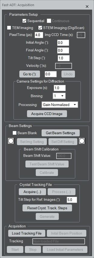
TUD, JGUM, UB 2020 Fast-ADT
First of all, the “Tilt Step for Ref. Images” has to be selected. From the experience in a Tecnai
Spirit, Tecnai F30 and JEOL 2100F with goniometric stages mechanically aligned for tomography, 5◦ is
a good value to subsequently interpolate the crystal positions for the tilt step of the 3D ED acquisition
(selected in the “Parameters Setup” module). If needed, this value can be modified for convenience of the
experimental setup.
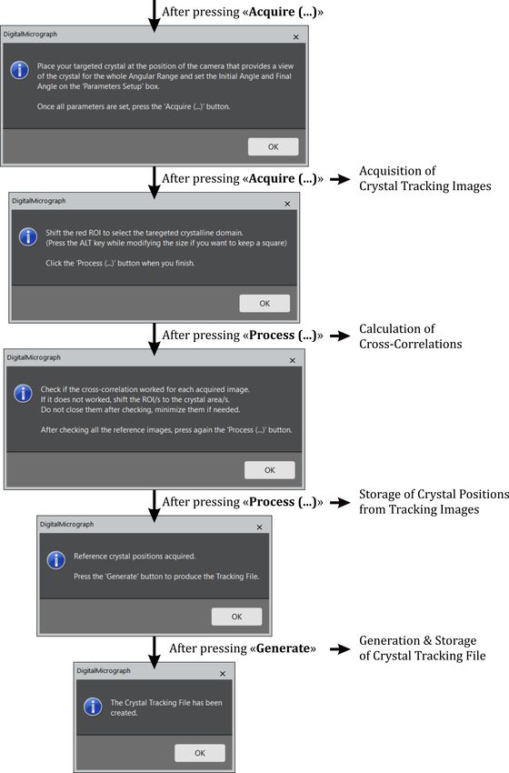
A first click on the “Acquire (...)” button will inform you about which steps have to be followed. Once
the targeted crystal has been positioned at the eucentric height, the selected magnification allows to see the
crystal in the camera during the whole selected angular range, and the values of the “Parameters Setup”
module are set according to your measurement, the “Acquire (...)” button can be pressed for a second time.
At this point, the stage will be tilted to the initial angle and an image will be acquired while increasing
the amount of “Tilt Step for Ref. Images” to the tilt angle for each acquisition. It is recommended to tilt
the stage to the initial angle manually with the “Go to” button at the “Parameters Setup” module before
clicking the “Acquire (...)” button for the second time in order to avoid the enhancement of hysteresis effects
from the stage motors.
After the acquisition of the tracking images up to the final angle, the image at the middle of the angular
range is shown with a red ROI to select the desired area to diffract during the 3D ED acquisition. Drag it
and resize it according to your desired diffracting domain. Once done, press the “Process (...)” button
to perform the cross-correlation calculation to all the other images. After the calculations, all reference
images will appear with a red ROI and the program asks to check all of them to ensure that the ROI is in
the selected crystal. If it is not correctly positioned, drag the ROI to select it properly. Do not close them
after the checking, just minimize them if they are bothering for the checking of the left ones. After this,
click again the “Process (...)” button that will store the positions of the crystal with respect to the tilt angle.
Finally, the “Generate” button will be enabled and by clicking it the program will ask to save the
crystal tracking file with a name in txt format. Subsequently, it will create and store the generated crystal
tracking file. Here, the tilt step can be changed if necessary and a new crystal tracking file can be generated
without going through the “Acquire (...)” and “Process (...)” steps. In case that the initial or final angle is
modified or other crystal is targeted, the “Acquire (...)” and “Process (...)” steps have to be followed prior
the the generation of the crystal tracking file. If the crystal is lost during the whole creation of the crystal
tracking process because the magnification was not set properly or for other reasons, click on the “Reset
Cryst. Track. Steps” button and start once again with the correct one.
7TUD, JGUM, UB 2020 Fast-ADT
5 Acquisition
To enhance the performance of the whole Fast-ADT acquisition process is recommended to not modify
the x, y and z position of the stage during the crystal tracking file generation as well as prior to run the
hereunder Acquisition part.
First of all, the “Load Tracking File” button is clicked and the generated crystal tracking is selected
to load it. If successfully loaded, the stage will automatically tilt to the initial angle and the initial beam
position can be selected.
Then, the “Initial Beam Position” button is clicked, a reference image is automatically acquired to
place a circle annotation (TEM mode) or a circular ROI (STEM mode) at the desired initial position. The
live display of the camera is also automatically started because the projector system has to be switched to
diffraction and the diffraction pattern has to be centred by the diffraction or projector shifts of the micro-
scope. Once done, the “Initial Beam Position” button is clicked once again to store the beam position, and
all images in the workspace are closed.
Prior to start the 3D ED acquisition, ensure that the diffraction lens is set to the correct value for the
diffraction acquisition and the STEM detector is retracted. In these conditions, the “Start” button can
be clicked to begin the 3D ED acquisition. The tilt angles in the parameters setup has to be the same as
the ones used for the generation of the tracking file. It is important to follow the “Initial Beam Position”
and the click of the “Start” button in a subsequent way in order to minimize the effect of the sample drift
on the mismatch of the current beam position and the selected place. By clicking the “Start” button, the
program will automatically tilt the stage, shift the beam according to the crystal tracking file and acquire
a diffraction pattern for each tilt step until the final angle is reached. Each diffraction pattern will be
displayed and refreshed during the whole acquisition. If the acquisition needs to be stopped, the “Stop”
button can be pressed and the acquisition procedure will stop after the last diffraction pattern is acquired.
8TUD, JGUM, UB 2020 Fast-ADT
At the end, the final stack of diffraction patterns will appear when the acquisition is stopped or finished,
which is automatically stored in C:\Program Files\FastADT_Storage to avoid missing data.
If a new acquisition has to be started with the same crystal tracking file, the “Load Initial Parameters”
button has to be pressed to automatically bring back the stage to the initial angle and re-set the internal
parameters for the acquisition. Once the stage is at the initial angle, the “Initial Beam Position” step has
to be followed before starting the 3D ED acquisition initialized by the “Start” button.
9TUD, JGUM, UB 2020 Fast-ADT
6 Data Formats
The pattern stacks obtained from the Fast-ADT program are automatically stored in .dm4 format because
the available calibration of the patterns according to the used camera length is stored in the metadata of
the file. Therefore, it can be checked from the raw data when necessary.
Two scripts are incorporated in the plug-in to split the stack in individual frames with DM3 or Tif
(unsigned 16-bit) format, which are formats usable for most of the data processing programs. To use them,
the stack file has to be displayed in the workspace that you are working and then the script can be clicked
in the Stack Split sub-menu of the Fast-ADT menu of Digital Micrograph. The script is asking a common
root name for the frames and then it is subsequently saving them with a 3 digit number as reference that
correspond to the order present in the stack.
10You can also read