SECOLOR TURNING CALCULATOR - USERS GUIDE
←
→
Page content transcription
If your browser does not render page correctly, please read the page content below
®
     SECOLOR
TURNING CALCULATOR
      USERS GUIDE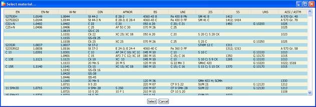
TABLE OF CONTENT
1 INTRODUCTION ............................................................................. 5
2 CALCULATIONS OF CUTTING SPEED .......................................... 6
2.1 SELECTION BY MATERIAL ............................................................. 6
2.2 SELECT MATERIAL FROM THE STANDARD DATA BASE ......... 7
2.3 CALIBRATE BY USING Rm OR HRC ................................................ 8
2.4 SELECT INSERT GRADE .................................................................. 9
3 INPUT............................................................................................... 9
3.1 HOLDER RAKE ANGLE.................................................................... 9
3.2 CHIPBREAKER................................................................................. 10
3.3 CUTTING EDGE ANGLE, r ........................................................... 10
3.4 NOSE RADIUS, r ............................................................................. 11
3.5 DEPTH OF CUT, ap .......................................................................... 11
3.6 FEED, f............................................................................................... 11
3.7 DESIRED TOOL LIFE ..................................................................... 11
3.8 KEEP VALUES .................................................................................. 11
3.9 CALCULATE .................................................................................... 12
3.10 COPY TO CLIPBOARD ................................................................... 12
VERSION HISTORY
REVISION CHART
Version Author(s) Description Date
1.0.0 SorH, EllS Release Version 1.0.0 2009-07-02DISCLAIMERS
The SECOLOR® Turning Calculator including this Users Guide is provided by Seco Tools “as is” and
“with all faults”. Seco Tools makes no representations or warranties of any kind concerning the quality,
safety or suitability of the SECOLOR® Turning Calculator including this Users Guide, either expressed
or implied, including without limitation any implied warranties of merchantability, fitness for a
particular purpose or non-infringement.
Seco Tools makes no representations or warranties as to the accuracy, reliability, completeness or
usefulness of any data provided by the SECOLOR® Turning Calculator or any information contained in
this Users Guide. The resulting speed recommendations provided by the SECOLOR® Turning
Calculator should only be considered as ‘start-values’ which may need to be modified due to individual
machinability properties of the actual work material, actual machine constraints, etc.
Seco Tools assumes no liability whatsoever for any loss resulting from the use of or inability to use the
SECOLOR® Turning Calculator including this Users Guide or from any reliance placed thereupon. In
no event shall Seco Tools be liable for any indirect, special, incidental or consequential damages
however they may arise, irregardless of whether Seco Tools has been previously advised of the possibility
of such damages.
There are inherent dangers in the use of any software available for download on the Internet and Seco
Tools cautions you to make sure that you completely understand the potential risks before downloading
the SECOLOR® Turning Calculator. Seco Tools will not be liable for any damages that you may suffer in
connection with downloading the SECOLOR® Turning Calculator.
Seco Tools has the proprietary and intellectual property rights to the SECOLOR® Turning Calculator,
the SECOLOR® trademark and the information contained in this Users Guide, except as otherwise
indicated, all of which rights are reserved. The SECOLOR® Turning Calculator including this Users
Guide may not, in whole or part, be copied, distributed or sold, nor may the information contained in
this Users Guide be used for design purposes without the express prior written permission of Seco
Tools.
The information in this Users Guide is provided for informational purposes only and is subject to
change without notice. Said information including this disclaimer may be revised at any time by
updating the posting on Seco Tools’ website.
-3-SYSTEM REQUIREMENTS
Windows XP or later Microsoft operating systems .NET Framework 3.5, Service pack 1
INSTALLATION
The system will automatically be downloaded and installed when clicking the download button.
UPDATES
If online and when starting the Secolor® Turning Calculator, the program will check if a new version is
available. If so, a button ‘Download latest version’ will appear on the upper right of the users interface
window. By clicking on this button the system will automatically be updated. (Click-once functionality)
The update may include either the systems functionality or the cutting data database or both.
TRADEMARKS
Secolor is a trademark of Seco Tool AB
Windows, Windows XP and .NET are trademarks of Microsoft Corporation
-4-1 INTRODUCTION
The Secolor Turning Calculator calculates recommendations for cutting speed, using he and Colding’s
tool life equation. The cutting speed recommendations are only available for applicable combinations
of materials and grades. The Calculator includes all turning grades and chip breakers, but has no
inbuilt product database. It is the responsibility of the user to make combinations of selections and
inputs that represent actual SECO products. For complete product selection, please see SecoCut 1 or
Seco Navigator.
All descriptions in this manual are based on the metric system but the functions are valid for inch as
well. Changing from the metric system to inch and vice versa can be done by any time.
Metric/Inch Chipbreaker
Select from list
Work material
Select from list
- SMG 1–15
- Superalloys
- Titanium
Calibration
- Rm for SMG 1-6
- HRC for SMG 7
Nominal values are used as
default.
Grade
Select from list
Language Material cross
Select from list reference specs
- Sort by desired
specification
- Select from list
Figure 1: Overview of input parameters and available selections in the
Secolor Turning Calculator
1
SecoCut can be downloaded from www.secotools.com. Since the SecoCut includes all the the Seco cutting tools, the size of the
database is 50Mb, and the download time as well as the required space on the local hard disc increases substantially.
-5-Selection of
material from Seco
material group
Selection by Selection
material of grade
Selection of
material from
Use default input
material standard
START values or change Calculate
data base
to desired values
Selection of
Selection
Selection by grade material from Seco
of grade
material group
RECOMMENDED
CUTTING SPEED vC AND
CHIP THICKNESS he
Figure 2: Selections available in the calculation process
2 CALCULATIONS OF CUTTING SPEED
There are two different preferences available for selection of parameters; selection by material and
selection by grade.
2.1 SELECTION BY MATERIAL
Selection by grade is similar.
Access and select materials from the Seco Material Groups (SMG)
-6-Seco Material Groups
SMG1 Low carbon – very soft steels, purely ferritic steels
SMG2 Free-cutting steels, except free-cutting stainless steels
SMG3 Structural steels, ordinary carbon steels with low to medium carbon content (0.5 %C)
SMG5 Normal tool steels, harder quenching and tempering steels
SMG6 Difficult tool steels, high-alloy steels, high hardness steels
SMG7 Difficult high strength steels, hardened steels, manganese steels
SMG8 Easy-cutting stainless steels, free-cutting stainless steels
SMG9 Moderately difficult stainless steels, austenitic and duplex steels
SMG10 Difficult stainless steels, austenitic and duplex steels
SMG11 Very difficult stainless steels, austenitic and duplex stainless steels
SMG12 Moderately hard grey cast iron
SMG13 Hard grey cast iron, malleable cast iron, nodular cast iron
SMG14 Difficult grey cast iron, moderately difficult malleable cast iron, nodular cast iron
SMG15 Very difficult grey cast iron, difficult malleable cast iron, nodular cast iron
SA Ni-based
SA Co-based
SA Fe-based
Titanium alloys
2.2 SELECT MATERIAL FROM THE STANDARD DATA BASE
To access the data base and materials organized into standards, see
Click on desired standard spec in the header, and the materials will be sorted in alphanumeric order.
Note that standards may be overlapping,
more than one instance of a standard
may occur. Compare with the other
standards to select the best fit.
Click on the desired material and press
“select”.
-7-Available standards:
EN New European standard European Committee for Standardization
EN-Nr New European standard European Committee for Standardization
W-Nr German standard Werkstoffnummer
DIN German standard Deutsches Institut für Normung
AFNOR French standard Association Française de Normalisation
BS British standard British Standard
UNI Italian standard Ente Nazionale Italiano di Unificazione
JIS Japanese standard Japanese Industrial Standards ()
SS Swedish standard Svensk Standard
UNS American standard Unified Numbering System
AISI/ASTM American standard American Iron and Steel Institute/
American Society for Testing and Materials
2.3 CALIBRATE BY USING Rm OR HRC
According to selected SMG group, Rm and HRC can be used for calibration.
For SMG 1-6 Rm
For SMG 7 HRC
For SMG 8-15 not available
By specifying the actual Rm or HRC value, the calculation is calibrated to reach increased accuracy for
SMG 1-7. Please note; when using inch, Rm is defined in ksi.
-8-2.4 SELECT INSERT GRADE
See type of grade on the underside of the insert boxes.
With the selected material, only the grades with available cutting data are listed. When using “selection
by grade”, only materials with available cutting data for the selected grade are listed.
Figure 3: Type of insert grade can be found on the underside of the insert box.
3 INPUT
All parameters have default values except chipbreakers, please adjust when needed. Values outside the
model will be identified by a red frame. Note that the calculator uses mathematical formulas to calculate
cutting speed; this means that cutting speed can be calculated for combined insert characteristics that
are not supported as actual products.
3.1 HOLDER RAKE ANGLE
See holder characteristics in catalogue, 0.
Figure 4: Holder rake angle, o in the holder properties shown in the catalogue.
-9-3.2 CHIPBREAKER
See insert characteristics
Figure 5: Chipbreaker type can be found on the underside of the insert box.
3.3 CUTTING EDGE ANGLE, r
Input range: [5° : 135°]
The cutting edge angle is the angle between cutting edge and direction of major feed and the working
cutting edge angle is the angle between cutting edge and the direction of working feed; please refer to
the examples below.
ap
a
p
r
r r
r
a r
p
f f
f
Figure 6: Longitudinal turning (Cutting Figure 7: Facing inwards Figure 8: Facing outwards
edge angle)
f
re
a
p r
r
f a
p
re
Figure 10: Taper outwards
Figure 9: Taper inwards - 10 -
(Working cutting edge angle)3.4 NOSE RADIUS, r
Input range: [0,1 : 3] mm
See insert characteristics
Figure 11: The nose radius can be found as the last two
figures in the identification number for the insert geometry.
This can be found on the underside of the insert box.
3.5 DEPTH OF CUT, ap
Input range: [r : 50] mm
The perpendicular direction to the feed. r
ap r
3.6 FEED, f
f
Input range: [0,05 : 0,5xrε] mm/rev
3.7 DESIRED TOOL LIFE
Figure 12: Definition of nose radius r, cutting depth ap,
feed f and cutting edge angle r
Estimated efficient cutting time may be changed to desired value
within model limits. Tool life selection range for the material groups;
ISO P SMG1-7 [3 : 60] minutes
ISO M SMG8-11 [2 : 40] minutes
ISO K SMG12-15 [3 : 60] minutes
Superalloys [2 : 20] minutes
3.8 KEEP VALUES
The default values in the input data may change for different selections of materials and insert grades.
To keep the selected input data for comparison to other material and grade selections, please check the
box ‘Keep values’.
- 11 -3.9 CALCULATE
Returns recommended cutting speed and chip thickness ( he ).
Traditional definition of he for general turning:
Figure 13: The definition of he
Ae
he = where Ae AD , be l SaD
be
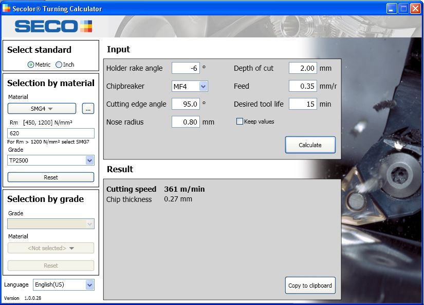
3.10 COPY TO CLIPBOARD
Copy to clipboard can be used to
Material SMG4
paste the results in other
documents. Rm 620 N/mm²
Grade TP2500
Holder rake angle -6 °
Chipbreaker MF4
Cutting edge angle 95.0 °
Nose radius 0.80 mm
Depth of cut 2.00 mm
Feed 0.35 mm/r
Desired tool life 15 min
Chip thickness 0.27 mm
Cutting speed 361 m/min
Figure 14: Cutting data pasted in cells. (The table
shown has been formatted after pasting.)
- 12 -You can also read