A COMBINED RADAR-RADIOMETER APPROACH TO ESTIMATE RAIN RATE PROFILE AND UNDERLYING SURFACE WIND SPEED OVER THE OCEAN
←
→
Page content transcription
If your browser does not render page correctly, please read the page content below
2nd Workshop of the International Precipitation Working Group

A COMBINED RADAR-RADIOMETER APPROACH TO ESTIMATE RAIN
RATE PROFILE AND UNDERLYING SURFACE WIND SPEED OVER THE
                         OCEAN

                            Shannon Brown and Christopher Ruf

                                  University of Michigan
                         2455 Hayward St. Ann Arbor, MI 48109, USA

                                           ABSTRACT

An algorithm is developed which combines the strengths of a 10.7 GHz microwave radiometer and
a 13.4 and 35.6 GHz Doppler radar to retrieve the rain rate profile and the surface wind speed
over the ocean. A dual-frequency radar algorithm is used to estimate two parameters of the
gamma drop size distribution at each range gate. The precipitation extinction/absorption profile
determined from the DSDs is used to remove the atmospheric contribution to the measured
brightness temperatures in order to estimate the surface wind speed. Radiometric retrievals in
light stratiform rain are driven by the absorption in the melting layer. Several melting layer models
are compared by assessing how well they fit the radar measurements in the melting layer. A
candidate model is chosen and its affect on the retrievals is analyzed.

1. INTRODUCTION

A retrieval algorithm has been developed which uses measurements of the backscattering
coefficient from the PR-2 dual-frequency Doppler radar and horizontally polarized brightness
temperature (TB) measurements from the LRR-X 10.7 GHz radiometer to simultaneously retrieve
the vertical profile of precipitation and the near-surface wind speed. Results are presented from a
field campaign in June of 2003 in which several DC-8 overflights were made in regions of
stratiform and convective precipitation associated with a mid-latitude cyclone off the coast of
Vancouver, British Columbia.

The retrieval algorithm uses the radar backscatter measurements at each frequency to iteratively
solve for two parameters of the gamma drop size distribution (GDSD) at each radar range gate. In
light rain, the measured backscatter is corrected for attenuation using a Hitschfeld-Bordan
approach (Hitschfeld and Bordan 1954). In this way, the attenuation is corrected top-down,
starting from the storm-top and progressing to the surface. The rain rate and liquid water content
at each range gate are determined by integrating the parameterized GDSDs. The surface wind
speed is determined from the 10.7 GHz TBs by removing the atmospheric component and isolating
the surface brightness, which monotonically increases with increasing surface wind speed. The
atmospheric optical depth is determined by integrating the 10.7 GHz extinction coefficient
determined at each rage gate using Mie theory with the parameterized GDSDs. The surface
emissivity is then found by inverting the radiative transfer equation and using the integrated optical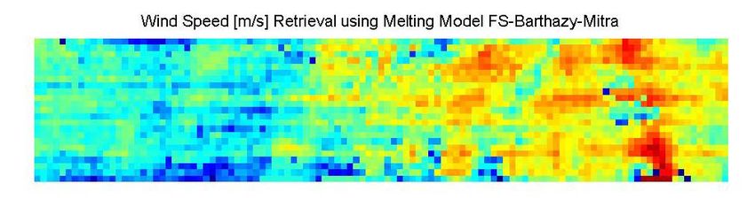
2nd Workshop of the International Precipitation Working Group

depth determined from the radar. A surface emissivity model is used to determine the near-
surface wind speed.

In light stratiform rain, the melting layer, which is usually less than 600 m thick, can contribute up
to 50 % of the atmospheric brightness, especially with low freezing levels. An example of this is
shown in Figure 1 for 10.7 GHz. Therefore, the accuracy any microwave radiometer retrieval in
stratiform rain is driven by the accuracy of the estimate of the absorption in the melting layer.
Several melting layer models exist (Klassen 1988; Bauer et al. 1999; Bauer et al. 2000; Olson et
al. 2001; Battaglia et al. 2003), and these are evaluated using the PR-2 and LRR data.

Figure 1. Fraction of the total atmospheric brightness from the melting layer at 10.7 GHz.

2. INSTRUMENT DESCRIPTION

The instruments used in this study are the JPL PR-2 Doppler radar, which operates at 13.4 and
35.6 GHz and the University of Michigan/GSFC LRR-X 10.7 GHz horizontally polarized
radiometer. The PR-2 mechanically scans cross-track to +25o and LRR-X electronically images
cross-track to +45o. The horizontal resolution of PR-2 is 800 m at the surface and LRR-X has a
500 m pixel resolution at the surface. The vertical resolution of PR-2 is 37 m. These instruments
were integrated on a NASA DC-8 in June of 2003 at which time several overflights of precipitation
were conducted.

3. MELTING LAYER MODELS

To determine the absorption and scattering in the melting layer one must use a thermodynamic
model to determine the melted mass fraction as a function of height below the top of the layer and
a dielectric mixing formula to determine the absorption and scattering coefficients for a given
melting particle. The thermodynamic formula will drive the thickness of the melting layer and the
choice of the dielectric model will determine the intensity of the absorption and scattering.

The melting rate of a snow particle that falls below the 273 K isotherm can be described in terms
of a thermodynamic heating budget (Mitra et al. 1990). This provides the melted mass fraction at
each height below the freezing level which is needed as input to a dielectric mixing formula. The
melting rate for a particle is determined by the choice of the ventilation coefficient (Mitra et al.
1990, Szyrmer and Zawadzki 1999) and the initial snow density as well as the environmental
2nd Workshop of the International Precipitation Working Group

parameters, such as the temperature lapse rate and the relative humidity. A high lapse rate will
cause the particle to melt faster. Contrary, if the relative humidity is low, the particle melting rate
will slow due to the sensible heat being used to evaporate the melt water.

A commonly used formula to determine the dielectric of a mixture of air, ice and water is the
Maxwell-Garnett (MG) mixing formula (Bohren and Battan 1982). The MG dielectric mixing
formula is defined in terms of the dielectric constant of the two components, one being the matrix
εm and the other the inclusions εi,

                                                 (1 − f )ε m + fβε i
                                        ε MG =
                                                     1 − f + fβ      ,                                 (1)
where
                                        2ε m    ⎡⎛ ε i ⎞             ⎛ε ⎞ ⎤
                                 β=             ⎢⎜⎜          ⎟⎟ Log ⎜⎜ i ⎟⎟ − 1⎥
                                      εi − εm   ⎣⎝ ε i − ε m ⎠       ⎝ εm ⎠ ⎦ ,

Log() is the principal value of the complex argument and f is the volume fraction of the inclusions.
For a three component mixture, such as a melting particle, the MG formula must be applied twice.
The resulting dielectric will depend on the volume fraction of the three components and the order
in which they are applied. The most often used forms are the MGwi and the MGiw (Bauer et al.
1999, Olson et al. 2001). The MGwi is defined as a water matrix with inclusions of an ice matrix
with air inclusions. The MGiw is defined as inclusions of water in a matrix with a dielectric
consisting of air inclusions in an ice matrix.. The following notation is defined to describe the
different combinations used,

{matrix | inclusion} Æ {matrix | {matrix | inclusion}}.

This gives MGwi = {water | {ice | air}} and MGiw = {{ice | air} | water}. The MGwi is very similar to the
dielectric of water and the MGiw is more similar to that of snow. Recent comparisons with radar
data have shown that the MGwi consistently over estimates the peak of the bright band and the
MGiw consistently underestimates the peak of the bright band (Battaglia et al. 2003). Other models
that have been used are { water | {air | ice}, { {water | ice} | air } (Klaassen 1988) and {air | {water |
ice}} (Battaglia et al. 2003).

Another model which blends two MG mixing formulas is the Fabry and Szyrmer (1999) coated
sphere model denoted FS. In this model, the melted particle is divided into a core and a shell that
have different densities, but the same melted mass fraction. The dielectric of the shell is given by
the MG formula {air | {water | ice}} and the dielectric of the core is given by { water | {air | ice}}.
This produces a result that blends the strongly absorbing core with the weakly absorbing shell.
The Fabry and Szyrmer model is a reasonable candidate, as it has compared favorably with radar
profiler measurements in the melting layer (Battaglia et al. 2003).

4. FITTING MELTING LAYER MODELS TO PR-2 DATA

These models are fit to the 13.4 and 35.6 GHz measured PR-2 profiles in the melting layer. The
stationary assumption is used to determine the number distribution of drops of diameter D in the
melting layer,

                                        N m ( D) = N w ( D)Vw ( D) / Vm ( D)                           (2)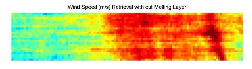
2nd Workshop of the International Precipitation Working Group
so the only input needed to model the reflectivity profile in the melting layer is the drop size
distribution at the base of the melting layer. The velocity of the melting particle Vm and the velocity
of the rain drop Vw are given in Battaglia et al. (2003). The drop size distribution retrievals at the
base of the melting layer are used as inputs to several of the melting layer models. An example of
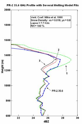
the melting layer model fits for both frequencies is shown in Figure 2.
Figure 2. Fitting the melting layer models to the 13.4 (left) and 35.6 (right) PR-2 reflectivity
profiles. Model 1 is {ice inclusions water matrix} | air, model 3 is air | {ice inclusions water matrix}
and model 2 is the FS model with core (model 1) and shell (model 2).
It can be seen in figure 2 that the FS core shell model fits the PR-2 data well. Table 1 provides a
summary of the statistics for the different dielectric models for approximately 100 profiles with
basal reflectivities of 25 – 31 dBZ. The best fit, in terms of the 13.4 peak bias, using different snow
densities and ventilation coefficients is shown for each dielectric model. The peak bias is the
model reflectivity peak minus the PR-2 reflectivity peak. The width difference is the standard
deviation of the model minus the standard deviation of the measurement. The fraction of the
opacity is the fraction of the total atmospheric extinction at 10.7 GHz due to the melting layer. The
mean wind speed is the average retrieved wind speed. It can be seen that models 1 and 2, which
overestimate the scattering, also overestimate the total atmospheric absorption. The average
wind speed outside the rain, as determined from the radiometer, is approximately 9-10 m/s.
The model that produced the best agreement with the PR-2 data is that which blends MG mixing
formulas, such as the FS core shell model. This model was applied to the wind and rain retrievals.
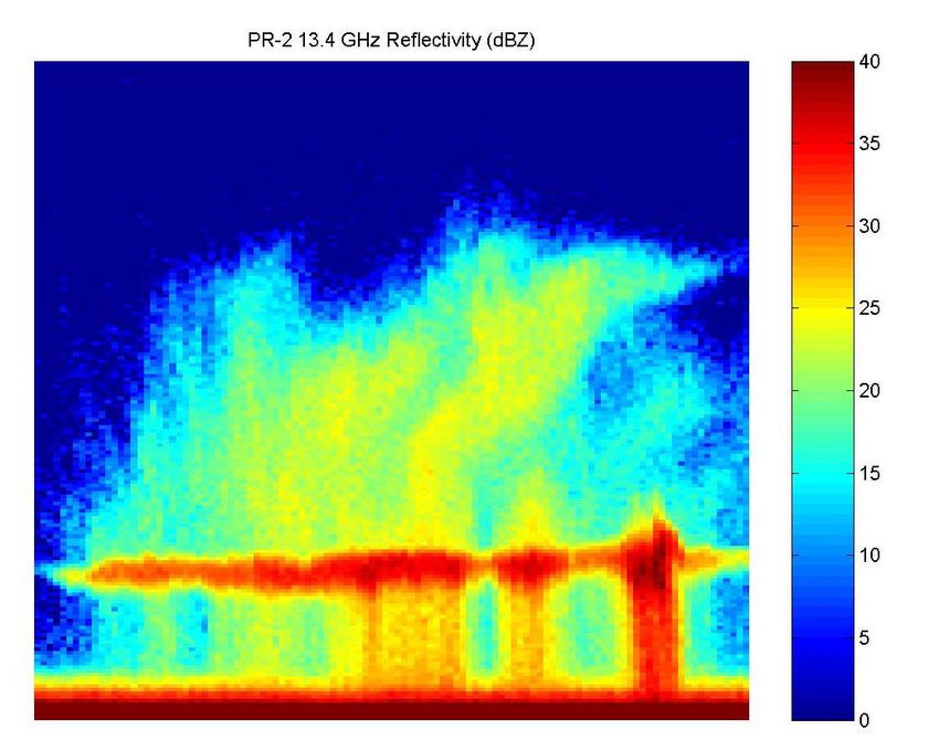
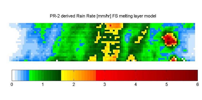
The retrieval using the FS core shell model is shown in Figures 3 – 6. Figure 3 shows the vertical
profile of the 13.4 GHz reflectivity, showing a strong melting layer in the middle of the image. The
retrieved wind speed without absorption from the melting layer is shown in Figure 4. Anomalously
high wind speeds are observed where the melting layer is intense. Figure 5 shows the rain layer
averaged rain rate retrieval from the radar for this storm. The rain rates are light, around 1 – 2
mm/hr, which means the 10.7 GHz absorption is mainly coming from the melting layer, as
observed in Figure 1. Figure 6 shows the retrieved wind speed using the FS dielectric model. It is
observed that this model is able to fit the PR-2 reflectivity profiles as well as produce reasonable
radiometric wind speed retrievals. The resulting wind speed retrieval in stratiform rain decreased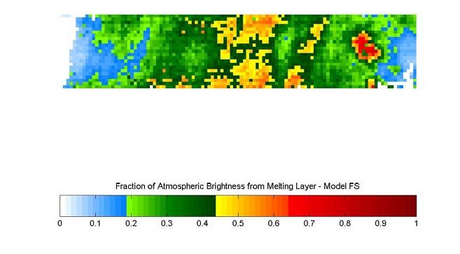
2nd Workshop of the International Precipitation Working Group

by 30 to 40 % as compared to no melting layer absorption, and the rain rate retrieval increased by
about 10 %.

         Dielectric Formula        13.4 Peak     35.6 Peak     13.4 Fraction Mean
                                     Bias        Bias (dB)    Width      of    Wind
                                      (dB)                   Dif. (dB) Opacity Speed
           (1) {Water | { air          5.2           3.1        1.4     0.72    0.03
           inclusions in ice
                matrix}
         (2) {ice inclusions |         3.8           2.5       1.0       0.66     0.63
          water matrix} | air}
          (3) Fabry-Szyrmer           -0.3           0.23     0.37       0.45      9.9
              Core-Shell
             (4) { air | {ice         -1.1          -0.43     -0.23      0.43     10.3
           inclusions water
                matrix}
          (5) {air inclusions         -2.3          -0.54     -0.52      0.32     12.1
            in ice matrix} |
                 water

Table 1. Fit to PR-2 data for different dielectric models.

Figure 3. 13.4 GHz reflectivity for a stratiform rain case. The melting layer is approximately at
1500 m above the surface.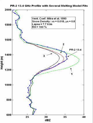
2nd Workshop of the International Precipitation Working Group

Figure 4. Rain rate retrieval using FS core shell model.

Figure 5. Wind speed retrieval without absorption from melting layer.

Figure 6. Wind speed retrieval using FS core shell model.
2nd Workshop of the International Precipitation Working Group

5. CONCLUSIONS

A retrieval algorithm is developed which uses dual-frequency radar backscatter measurements to
profile the drop size distribution. The drop size distribution is used to determine the rain rate and
liquid water content profile. The surface wind speed is estimated from the measured emissivity of
the sea at 10.7 GHz, where the atmospheric clearing of the brightness temperature comes from
the absorption and extinction coefficient profiles determined from the DSD. In stratiform rain, the
retrieval is driven by the absorption in the melting layer. This requires an accurate model for the
melting layer. Several models were fit to the PR-2 data, and the Fabry and Szyrmer core shell
model was selected as the candidate model for the algorithm. Anomalously high wind speed
retrievals with no melting layer were reduced by 30 to 40 % with the addition of the melting layer
model and the radar retrieved rain rates were increased by 10 %.

6. REFERENCES

Battaglia, A., C. Kummerow, D. Shin and C. Williams. 2003. Constraining Microwave Brightness
Temperatures by Radar Brightband Observations. J. Atmos. and Oceanic Tech, 20, pp 856-871.

Bauer, P., A. Khain, A. Pokrovsky, R. Meneghini, C. Kummerow, F. Marzano and J. Baptista.
2000. Combined Cloud-Microwave Radiative Transfer Modeling of Stratiform Rain. J. Atmos.
Sci., 57, pp 1082-1104.

Bauer, P. J. Baptista and M Iulis. 1999. The Effect of the Melting Layer on the Microwave
Emission of Clouds over the Ocean. J. Atmos. Sci., 56, pp 852-867.

Bohren, C. and L. Battan. 1982. Radar Backscattering of Microwaves by Spongy Ice Spheres. J.
Atmos. Sci., 39, pp 2623-2628.

Fabry, F. and W. Szyrmer. 1999. Modeling of the Melting Layer. Part II: Electromagnetic. J.
Atmos. Sci., 56, pp 3593-3600.

Hitschfeld W. and J. Bordan. 1954. Errors Inherent in the Radar Measurement of Rainfall at
Attenuating Wavelengths. J. of Meteor., 11, pp 58-67.

Klassen, W. 1988. Radar Observations and Simulation of the Melting Layer of Precipitation. J.
Atmos. Sci. 45. 3741-3753. J. Atmos. Sci., 56, pp 852-867.

Mitra, S. O. Vohl, M. Ahr and H. Pruppacher. 1990. A Wind Tunnel and Theoretical Study of the
Melting Behavior of Atmospheric Ice Particles. IV: Experiment and Theory for Snow Flakes. J.
Atmos. Sci., 47, pp 584-591.

Olson, W., P. Bauer, N. Viltard, D. Johnson, W. Tao, R. Meneghini and L. Liao. 2001. A Melting-
Layer Model for Passive/Active Microwave Remote Sensing Applications. Part I: Model
Formulation and Comparison with Observations. J. Appl. Meteor., 40, pp 1145-1163.

Pandey, P. and R. Kakar. 1982. An Empirical Microwave Emissivity Model for a Foam-Covered
Sea. IEEE J. Oceanic. Eng., 7, pp 135-140.

Szyrmer W. and I. Zawadzki. 1999. Modeling of the Melting Layer. Part I: Dynamics and
Microphysics. J. Atmos. Sci., 56, pp 3573-3592.
You can also read