A Non-Lethal Electric Shock Generator with Wireless Control Function - IOPscience
←
→
Page content transcription
If your browser does not render page correctly, please read the page content below
Journal of Physics: Conference Series

PAPER • OPEN ACCESS

A Non-Lethal Electric Shock Generator with Wireless Control Function
To cite this article: Chunxia Yang et al 2020 J. Phys.: Conf. Ser. 1507 072028

View the article online for updates and enhancements.

                                This content was downloaded from IP address 176.9.8.24 on 24/09/2020 at 06:44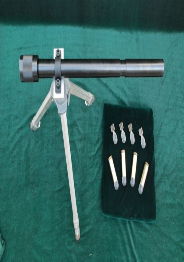
The 2020 Spring International Conference on Defence Technology                                                  IOP Publishing
Journal of Physics: Conference Series           1507 (2020) 072028                        doi:10.1088/1742-6596/1507/7/072028

A Non-Lethal Electric Shock Generator with
Wireless Control Function
                      Chunxia Yang1 , Gang Wan1 , Jian Liu1 , Wenxuan Zhang1 , Hui Tian1 ,
                      Zhenxiao Li1 , Yong Jin1 , and Baoming Li1,2
                      1 National Key Laboratory of Transient Physics, Nanjing University of Science and
                      Technology, Nanjing 210094, Jiangsu, China
                      2 China Academy of Ordnance, 100089, Beijing, China
                      E-mail: baomingli@njust.edu.cn

                      Abstract. A Non-lethal electric shock generator is presented and tested. This non-lethal
                      electric shock generator without trail wires, is different from Taser series stun guns or Husha
                      TX series electric shock guns which all have trail wires. And the intensity of electric shock
                      can be adjusted by remote control device according to the status of the target. This no-lethal
                      electric shock generator extends the range of application of electric shock from about 9 meters to
                      30 meters. The manner of using electric shocks of single intensity is also changed by telecontrol
                      adjustment. It can provide electric shocks of different intensities for different conditions, such as
                      different distances from special electrodes to targets, different targets with different clothes and
                      different height or weight. Basic functions of the non-lethal electric shock generator are tested.
                      Results show that the prototype projectile can be launched from a barrel stably, and the flight
                      range is over 30 meters. When it captured the target, it can be triggered via the telecontrol
                      adjustment. The prototype projectile can support a series of pulses at a rate of 20 r/s with the
                      peak voltage of 30kV.

1. Introduction
As early as in the 1970s, the first generation of electric shock guns came out in the United
States. Stun gun works with firing two tethered barbs at a target and sending electric pulses
into the target through tether wires. Electronic stun guns have been developed as non-lethal
devices that people can employ to defend or control potentially dangerous conditions. These
stun guns support high voltage, low amperage, pulsatile electric shocks to the target, which
causes involuntary skeletal muscle contraction and renders the target unable to further threat.
The duration of these discomfort with electric shock is short in time, and human body can
quickly return to normal. Now, common stun guns in Europe and America, such as Taser M18,
M26, X26 and in China, such as Husha TX200, all have trail wires, which limit the distance of
application. Two insulated conductive wires of Taser X26 trail behind for up to 9 meters, to
make contact with their target and complete the electrical circuit. Wires play an essential role
in sending muscle-locking electric pulses into the target and fix the application scope of electric
shock within 9 meters [1–6]. Song Yansheng gave design ideas and parameters of a new type of
electric shock bullet. Its designed working range is 30 meters with 5kV shock voltage [7]. While
Taser X26 provides an open-circuit peak voltage of 50kV and delivers a peak voltage of 1.2kV
to the targets body. Lei Hailiang put forward a concept of a long-range electric shock bullet for

              Content from this work may be used under the terms of the Creative Commons Attribution 3.0 licence. Any further distribution
              of this work must maintain attribution to the author(s) and the title of the work, journal citation and DOI.
Published under licence by IOP Publishing Ltd                          1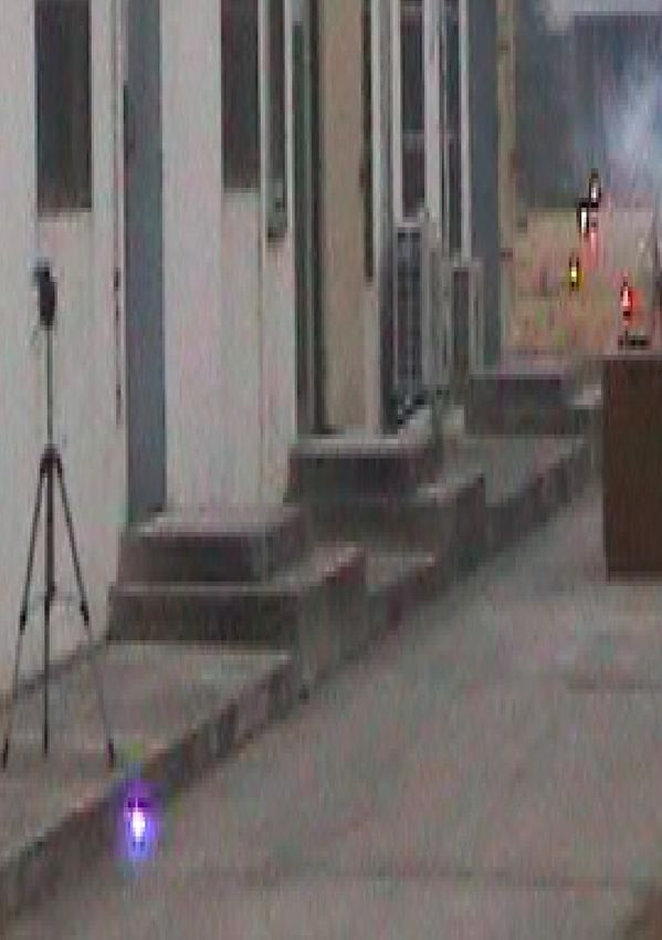
The 2020 Spring International Conference on Defence Technology                             IOP Publishing
Journal of Physics: Conference Series           1507 (2020) 072028   doi:10.1088/1742-6596/1507/7/072028

Rifle shot gun to increase the range by using electromagnetic induction [8].
   In this paper, a non-lethal electric shock generator is designed and tested. The special
electrodes in the generator is designed to support electric shocks of different densities after
flying out from the launcher via a remote control device. This no-lethal electric shock generator
can extend the range of application of electric shock to tens meters. Three non-lethal electric
shock generator prototypes are manufactured and some tests as the corresponding discharge
test, remote control test, preliminary flight test and integrated launch test are introduced to
estimate the reliability and stability of the non-lethal electric shock generator.

2. A non-lethal electric shock generator
The non-lethal electric shock generator includes a firing element, propellant, a battery, a boost
module, a high voltage rectifier control and discharge module (HVGCM), a telecontrol module
(signal receiving circuit), a proximity module, two barb electrodes, etc. The schematic diagram
of the non-lethal electric shock generator is shown in figure 1. The design value of the mass is
about 30g. The diameter of the main part is 25mm. And the distance between two electrodes
is 14mm.

                                            Figure 1.    Schematic diagram
                                            of the non-lethal electric shock
                                            generator.

   Working process of the non-lethal electric shock generator is as following. Firstly, the non-
lethal electric shock generator is put into the launcher and the inertia and firing safety is turned
on. Then the battery charges the high voltage generating module. Getting the signal from firing
sensor, propellant is ignited by firing element. With the combustion of propellant, the chamber
pressure increases, and the non-lethal electric shock generator is accelerated to fly to the target.
Then proximity switch is turned on. The telecontrol module works with receiving signal from
the remote-control device. Finally, the high voltage rectification and discharge module releases
electric shock to the target through the barb electrodes according to the control command.

Figure 2. Schematic diagram of              Figure 3. Simulation curve of
the discharging circuit.                    output voltage of the HVGCM.

                                                    2
The 2020 Spring International Conference on Defence Technology                             IOP Publishing
Journal of Physics: Conference Series           1507 (2020) 072028   doi:10.1088/1742-6596/1507/7/072028

    The HVGCM is the core part of the non-lethal electric shock generator. It plays a crucial role
in sending the electric shock to the target. Figure 2 is the schematic diagram of the discharging
circuit. The high voltage input A is provided by previous boost circuit. Its value is about
1kV. After high voltage A is input, a capacitor C is charged through a resister R. When the
voltage on the capacitor C reaches a certain value, a controller B sends a control command to
the electronic control switch K. The capacitor C discharges the high voltage to transformer T
through the electronic control switch. After the boosting transformation, the voltage between
two electrodes would be 30kV to 40kV. Figure 3 is a simulation diagram of the output voltage.
The input voltage of battery is 7V. And the peak voltage and pulse width of the gap discharge
is about 30kV and 50ms, respectively.

3. Tests and discussions
3.1. Static discharge test
The non-lethal electric generator prototypes are manufactured after the components are
completed. The static discharge test is introduced to evaluate the discharge characters of the
non-lethal electric generator prototypes. Figure 4 is the photograph of the static discharge test.

Figure 4. Photograph of the static          Figure 5. Test curve of output
discharge test.                             voltage of the HVGCM.

   Voltages at electrodes is attenuated by a high voltage probe and displayed on the
oscillographic digital multimeter. The magnification of the high voltage probe is 1000. The
static discharge test steps are shown as following. (1) Connect the positive and the negative
poles of the high voltage probe with the discharge electrodes. (2) Connect the high voltage probe
to the oscillographic digital multimeter. (3) Turn on the multimeter and adjust the horizontal
coordinate to the center of the screen. Set the sensitivity of oscillographic digital multimeter to
5V. Set the trigger level of the oscillographic digital multimeter to 0.5V. Set the time interval
of the oscillographic digital multimeter to 5ms. (4) Turn on the charging switch. (5) Press the
control button. (6) Store the waveform recorded by the oscillographic digital multimeter.
   By pressing the white button in the remote-control device, a brief arcing pulse was generated,
which ionizes the intervening air to establish a conductive path for the electricity. The red circle
in figure 4 marks out the discharge arc. Figure 5 is the test curve of the voltage between two
electrodes. As shown in figure 5, the peak voltage fluctuates between -20kV and 40kV. The
average forward peak voltage is nearly 30kV and pulse width is about 50ms, similar to the
simulation results in figure 4. The difference between test and simulation curves is that the
peak voltage of test curve is less stable than the simulation curve. That is because the actual
air resistance is more complex than the analog resistance.

                                                    3
The 2020 Spring International Conference on Defence Technology IOP Publishing
Journal of Physics: Conference Series 1507 (2020) 072028 doi:10.1088/1742-6596/1507/7/072028
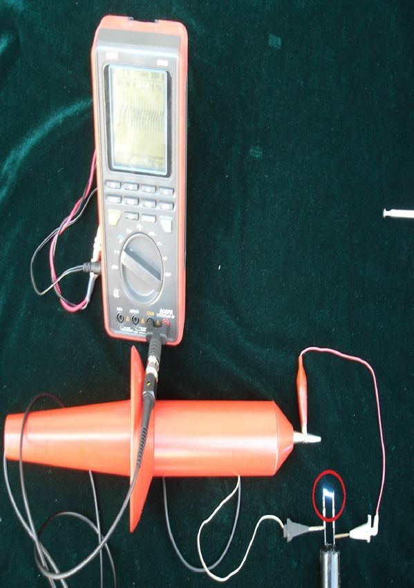
3.2. Simulated projectile launch test
In order to test the flight stability of the non-lethal electric generator, a simulated projectile
with the same quality and external shape is manufactured.
Figure 6. Photograph of the
launch device and simulated projec-
tiles.
The photograph of the launch device and simulated projectiles is shown in figure 6. The
caliber of the launcher is 25mm. And the barrel length is 517mm. The average mass of
the simulated projectiles is 30.1g. A set of this launch tests are executed. All five simulated
projectiles reached the target 30m far from the barrel muzzle. Hence, the firing range of this
projectile is more than 30m.
3.3. Integrated launch test
The integrated launch test of the non-lethal electric shock generator prototypes are executed
after the above tests. Figure 7 is the photograph of the launch device and the non-lethal electric
shock generator prototype. The launch device is the same with in the simulated projectile launch
tests. The average mass of the non-lethal electric shock generator prototypes is 30.0g.
Figure 7. Photograph of the
Figure 8. Photograph of the
launch device and the non-lethal
integrated launch test.
electric shock generator prototype.
Figure 8 is the photograph of the integrated launch test scene. The launch device is placed on
the wooden box at the upper right of figure 8. The bright spot in the lower left corner of figure 8
is the non-lethal electric shock generator prototype. And it is supporting the high voltage pulses
right now in figure 8. Therefore, the basic functions had been verified.
4. Summary
A Non-lethal electric shock generator is presented and tested. It can provide electric shocks of
different intensities for different conditions, such as different distances from special electrodes
to targets, different targets with different clothes and different height or weight. A long range
4
The 2020 Spring International Conference on Defence Technology                                 IOP Publishing
Journal of Physics: Conference Series           1507 (2020) 072028       doi:10.1088/1742-6596/1507/7/072028

discharge is provided by a 25mm barrel launcher. The basic functions of the non-lethal electric
shock generator are tested. Results show that the prototype projectile can be launched from
a barrel stably, and the flight range is over 30 meters. When it captured the target, it can be
triggered via the telecontrol adjustment. The prototype projectile can support a series of pulses
at a rate of 20 r/s with the peak voltage of 30kV.

References
[1]   Upson S 2008 IEEE Spectrum 44 25–31
[2]   Dawes D M, Ho J D, Reardon R F and Miner J R 2017 American journal of emergency medicine 35
[3]   Zhou W and Zhong X 2019 Journal of Liaoning Police College 21 81–84
[4]   Tseng S Y, Hsu G W, Jhuang Y R, Fan S Y and Chang G K 2011 High voltage generator using rapid response
        boost / flyback converters for stun gun applications Industrial Electronics & Applications. IEEE
[5]   Mcdaniel W, Benwell A and Kovaleski S 2009 Conference proceedings : Annual International Conference of
        the IEEE Engineering in Medicine and Biology Society. IEEE Engineering in Medicine and Biology Society.
        Conference 2009 3184–7
[6]   Dawson D, Maimaitijiang Y and Adler A 2010 Development of a performance calibration system for x-26
        tasers Medical Measurements and Applications Proceedings (MeMeA), 2010 IEEE International Workshop
        on
[7]   Song Y S 2017 Journal of Ordnance Equipment Engineering 38 27–29
[8]   Lei H and Zhan R 2019 Modern Manufacturing Technology Equipment 30–31

                                                        5
You can also read