Accurate and rapid IR metrology for the manufacture of freeform optics
←
→
Page content transcription
If your browser does not render page correctly, please read the page content below
10.1117/2.1201506.006015
Accurate and rapid IR metrology
for the manufacture of freeform
optics
Dae Wook Kim, Tianquan Su, Peng Su, Chang-jin Oh,
Logan Graves, and James Burge
A novel deflectometry system has high dynamic range and fine spatial
resolution metrology capabilities.
The freeform revolution continues to redefine mainstream
optics fields. Specific applications of freeform optics are cur-
rently prevented, however, because there is a lack of accurate
metrology methods to guide efficient fabrication. The wide
and flexible design space of freeform optics allows the design
of new cutting-edge optical system concepts and form factors.
Some next-generation astronomy telescopes use these systems
to achieve improved performance. For instance, the Giant
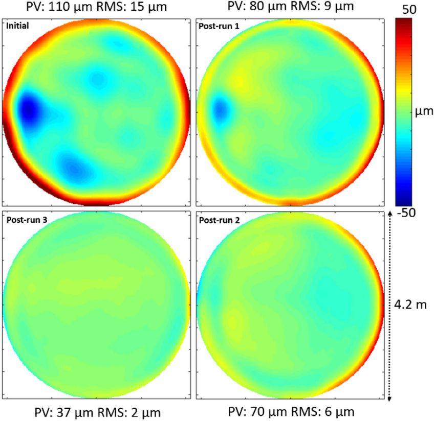
Magellan Telescope (GMT) combines multiple highly aspheric Figure 1. Photograph of the Scanning Long-wave Optical Test System
freeform primary mirror segments.1 A rapid precision manu- (SLOTS). The long-wave IR (LWIR) camera (red arrow) and the tung-
facturing technology is thus one of the remaining pieces that sten ribbon IR source (blue arrow) are indicated.3
prevents full realization of a freeform age, which will make
complex tailored optics a tangible reality.
to make direct measurements of local slopes and rapidly provide
To achieve a rapid optics manufacturing process, it is highly
highly accurate surface profiles of optical surfaces. In our
desirable (because of the high material removal rate) to have
Scanning Long-wave Optical Test System (SLOTS), we use a
precise surface figuring during the grinding phase. A surface
scanning thermal long-wave IR (LWIR) source to produce a
error that requires one minute of grinding, for instance, can
7–14m spectrum that is reflected efficiently by rough optical
easily take more than 1000 minutes if it is removed during the
surfaces. We are able to use SLOTS to produce accurate surface
polishing phase. Such grinding processes, however, are mostly
maps of ground freeform optics that have a surface roughness
limited by available metrology techniques. Current grinding
of about 0.7–1.6m root mean square (RMS). In addition, we can
phase metrology options include the use of a laser tracker2 or
achieve an accuracy of nearly 1m with high spatial resolution
an IR interferometer, but these are often limited by coarse spa-
(400400 pixels) and a large dynamic range (e.g., 9mm freeform
tial resolution, low accuracy, or low dynamic range. Addition-
departure over a test surface with a diameter of 4.2m). The fast
ally the IR interferometer requires an expensive custom null IR
scanning capability of SLOTS also means that the total measure-
optics system to measure freeform surfaces.
ment time is short, e.g., an entire 4.2m-diameter test surface can
We have developed a new IR deflectometry (the deflection of
be measured in less than a minute.
light from a known source is measured, and the profile of the
surface with which the light interacted is determined via back
calculations) system (see Figure 1) that overcomes the limita-
tions of existing metrology approaches.3, 4 We use deflectometry Continued on next page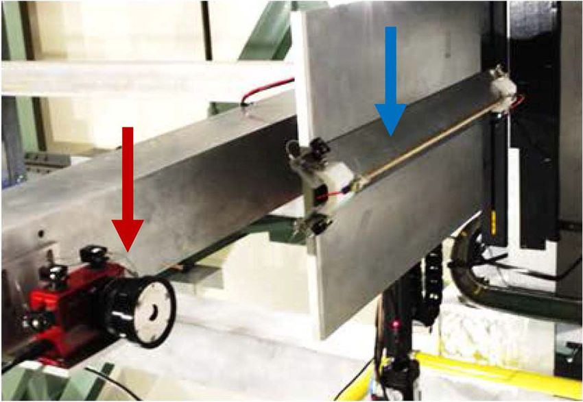
10.1117/2.1201506.006015 Page 2/3
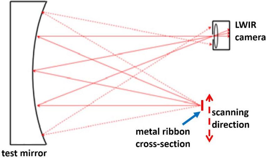
A schematic diagram illustrating our SLOTS deflectometry
concept is shown in Figure 2. First, a tungsten ribbon (at
300◦C) is scanned and emits LWIR radiation in two orthogonal
directions.3, 4 Some of the rays from the ribbon are reflected by
the test surface and propagate toward the LWIR camera aper-
ture. We configure this camera to image the test surface plane so
Figure 4. Photograph of the 4.2m-diameter Daniel K. Inouye Solar
Telescope (DKIST) primary mirror at the College of Optical Sciences,
University of Arizona.3, 6
Figure 2. Schematic diagram of the SLOTS deflectometry concept.
Solid red lines represent IR rays (emitted from the hot tungsten rib-
bon) propagating toward the detector of the LWIR camera.
Figure 5. (a) Freeform aspheric departure of the DKIST primary
mirror. (b) High-order shape with the first eight standard Zernike
terms removed (right). Peak-to-valley (PV) and root mean square
(RMS) statistics are shown for both sets of data.
that each camera pixel corresponds to a local test surface area.
We match the temporal position of the ribbon and the tempo-
ral intensity change of the thermal image during a scan. We
are therefore able to directly calculate—based on a simple ray-
trace (i.e., the solid red lines in Figure 2)—the local slopes of the
test surface, and we integrate these to obtain the surface height.
A sequence of four camera images that we captured during a
continuous scan is shown in Figure 3. As the hot tungsten rib-
bon is scanned, only some areas (which appear bright in each
image) on the test surface have local slopes that reflect LWIR
light so that it passes through the camera aperture and on to the
detector.
We have successfully used SLOTS to guide the grinding of
the 4.2m-diameter primary mirror for the Daniel K. Inouye
Solar Telescope (DKIST), which is shown in Figure 4.3, 6, 7 This
Figure 3. Four images captured using the LWIR camera during a off-axis parabolic primary mirror has a freeform departure—see
SLOTS scanning process. Bright areas have local slopes that reflect Figure 5(a)—of about 9mm maximum deviation. We have
LWIR light so that it passes through the camera aperture and on to the
detector. (Watch a short video of this sequence.5 ) Continued on next page
10.1117/2.1201506.006015 Page 3/3

                                                                        off-axis segments). We also hope to use SLOTS to guide the
                                                                        manufacturing of other freeform optics components that have
                                                                        rough surface finishes (e.g., for additive 3D printing
                                                                        technologies).

                                                                        This material is partly based on work performed for DKIST. DKIST
                                                                        is managed by the National Solar Observatory, which is operated by
                                                                        the Association of Universities for Research in Astronomy Inc. under
                                                                        a cooperative agreement with the National Science Foundation.

                                                                        Author Information

                                                                        Dae Wook Kim, Tianquan Su, Peng Su, Chang-jin Oh,
                                                                        Logan Graves, and James Burge
                                                                        College of Optical Sciences
                                                                        University of Arizona
                                                                        Tucson, AZ

                                                                        Dae Wook Kim is an optical scientist. He received his BSc in
                                                                        physics and astronomy from Yonsei University, South Korea,
Figure 6. Illustration of the rapid evolution of DKIST primary mirror
                                                                        and his PhD in optical sciences from the University of Arizona.
surface shape errors (from the ideal shape). These measurements were
                                                                        He has served as associate editor of Optics Express and as an SPIE
obtained during three successive computer-controlled fine-grinding
                                                                        conference chair for Optical Manufacturing and Testing.
runs, which had a total run time of about 97 hours.
                                                                        References
                                                                        1. H. M. Martin, R. G. Allen, J. H. Burge, D. W. Kim, J. S. Kingsley, K. Law, R. D.
also calculated the higher-order shape departure that remains           Lutz, et al., Production of 8.4m segments for the Giant Magellan Telescope, Proc. SPIE
                                                                        8450, p. 84502D, 2012. doi:10.1117/12.926347
after subtracting the first eight standard Zernike terms: see           2. T. L. Zobrist, J. H. Burge, and H. M. Martin, Accuracy of laser tracker mea-
Figure 5(b).                                                            surements of the GMT 8.4-m off-axis mirror segments, Proc. SPIE 7739,
                                                                        p. 77390S, 2010. doi:10.1117/12.856520
   In addition, we have performed deterministic fine grinding           3. D. W. Kim, C. J. Oh, P. Su, and J. H. Burge, Advanced Technology Solar
runs—using 25m loose abrasive grits—which were based on                Telescope 4.2m off-axis primary mirror fabrication, Class. Opt., p. OTh2B.3, 2014.
                                                                        doi:10.1364/OFT.2014.OTh2B.3
SLOTS data. The evolution of the DKIST primary mirror sur-
                                                                        4. T. Su, S. Wang, R. E. Parks, P. Su, and J. H. Burge, Measuring rough optical surfaces
face error (from its ideal shape) that we measured with SLOTS           using scanning long-wave optical test system. 1. Principle and implementation, Appl.
is presented in Figure 6. During three successive runs (about 97        Opt. 52, pp. 7117–7126, 2013.
                                                                        5. http://spie.org/documents/newsroom/videos/6015/Media1.wmv Video of a
hours in total), we targeted the high-resolution initial error map      real-time thermal image measured using the Scanning Long-wave Optical Test Sys-
that pinpoints all the critical mid-to-high spatial frequency           tem. Credit: Tianquan Su, University of Arizona.
                                                                        6. D. W. Kim, P. Su, C. J. Oh, and J. Burge, Extremely large freeform optics manufactur-
errors (e.g., edge shape). We were able to improve the RMS sur-         ing and testing, pp. 26F1–1, 2015. Paper accepted at the Conf. Lasers Electro-Opt.
face shape error from 15 to 2m.6                                       Pacific Rim (CLEO-PR) in Busan, Korea, 24–28 August 2015.
                                                                        7. J. P. McMullin, T. R. Rimmele, S. L. Keil, M. Warner, S. Barden, S. Bulau, S. Craig,
   Our new IR deflectometry system—known as SLOTS—                      et al., The Advanced Technology Solar Telescope: design and early construction, Proc. SPIE
represents an accurate method for rapid metrology of finely             8444, p. 844407, 2012. doi:10.1117/12.926949
ground freeform optical surfaces. SLOTS now provides an op-
portunity to use ambitious and aggressive computer-controlled
optical surfacing (CCOS) processes during early optics grind-
ing phases. Our tests have shown the rapid convergence of the
DKIST primary mirror during the grinding phase. This indicates
that coupling CCOS processes with our new metrology system
can lead to substantial reduction in freeform fabrication times.
We are now planning to use SLOTS for various future
astronomical optics manufacturing projects (e.g., for the GMT                                                 c 2015 SPIE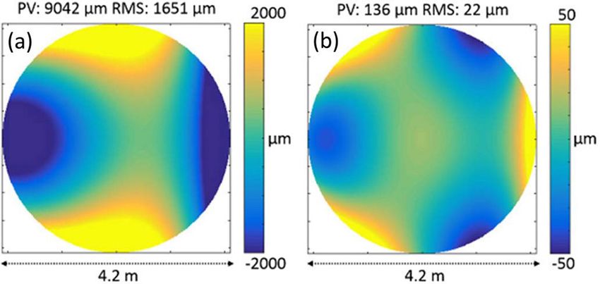
You can also read