Through-the-Wall Wine Cellar Cooling System - Wine Racks America
←
→
Page content transcription
If your browser does not render page correctly, please read the page content below
Through-the-Wall
             Wine Cellar Cooling System

            Quick Start Installation Guide
This document is a pictorial guide for installing the Wine Guardi-
an Through-the-Wall (TTW) system. It is not intended to replace
  the detailed instructions found in the TTW Installation, Opera-
 tion and Maintenance (IOM) manual, which includes important
 safety messages all installers and owners should follow for safe
and optimal performance of the system. Refer to the IOM manu-
 al for installation instructions related to duct collars, duct collar
    kits, remote interface controls, or remote sensors. Complete
  IOM manuals may be found on the Resources & Manuals page
 of the Wine Guardian website. If you have additional questions
   related your Wine Guardian TTW system, please contact your
          authorized Wine Guardian distributor or your local
                         Wine Guardian office.

                      www.wineguardian.com
           USA +1 315-452-7400 | Europe +41 52 224 0490
                      info@wineguardian.com
Deutsch                                     Seite 6
            Wine Guardian Weinkellerkühlsystem zum Wandeinbau
Dieses Dokument ist eine bebilderte Installationsanleitung für das Wine
Guardian-Wandeinbausystem (WES). Diese Anleitung soll nicht die
detaillierten Anweisungen des WES Installations-, Bedienungs- und
Wartungshandbuchs (IBW) ersetzen, das wichtige Sicherheitsinformationen
enthält, die alle Installateure und Besitzer für einen sicheren und optimalen
Betrieb des Systems befolgen sollten. Für die Installationsanweisungen von
Leitungsmanschetten, Leitungsmanschetten-Kits, Fernbedienungen oder
Fernfühlern, ziehen Sie bitte das IBW-Handbuch zu Rate. Vollständige IBW-
Handbücher finden Sie im Abschnitt „Ressourcen und Handbücher“ auf der
Wine Guardian-Internetseite. Wenn Sie weitere Fragen zu Ihrem Wine
Guardian WES haben, kontaktieren Sie Ihren autorisierten Wine Guardian-
Vertriebspartner oder Ihr örtliches Wine Guardian-Büro.

Español                                    página 8
           Wine Guardian - Bodega refrigerada empotrada en la pared
Este documento es una guía con imágenes para la instalación del sistema
Wine Guardian empotrado en la pared. Esta guía no reemplaza las instruccio-
nes ampliadas que se pueden encontrar en el manual de instalación, opera-
ción y mantenimiento (IOM) que incluye mensajes importantes sobre seguri-
dad que todos los instaladores y propietarios deberían seguir para un rendi-
miento seguro y óptimo del sistema. Consulte los manuales IOM para encon-
trar las instrucciones de instalación de los collares de conducto, los kits de
collares de conducto, la interfaz de controles remotos, o los sensores remo-
tos. Los manuales IOM completos se pueden encontrar en la sección de Re-
cursos y Manuales en la página web de Wine Guardian. Si tiene más pregun-
tas sobre su sistema Wine Guardian, por favor póngase en contacto con su
distribuidor de Wine Guardian autorizado o con la oficina de Wine Guardian
más cercana.

Français                                   page 10
               Wine Guardian Climatiseur de cave à vin traversant
Ce document est un guide illustré pour l’installation de votre climatiseur tra-
versant Wine Guardian. Il n’a pas pour objet de remplacer les instructions
détaillées du manuel d’installation, de fonctionnement et d’entretien, lequel
comprend d’importants messages de sécurité que tout installateur et pro-
priétaire doit suivre pour garantir un fonctionnement sécurisé et optimal du
climatiseur. Référez-vous au manuel d’installation, de fonctionnement et
d’entretien pour les consignes de montage des colliers pour conduits, des kits
de colliers et des capteurs à distance. Vous pouvez trouver des manuels d’ins-
tallation, de fonctionnement et d’entretien sur la page Ressources et Ma-
nuels de notre site internet Wine Guardian. Pour toute autre question con-
cernant les commandes de l’interface de votre climatiseur traversant Wine
Guardian, veuillez contacter votre distributeur Wine Guardian agréé ou la
filiale Wine Guardian locale.
                                       2
Italiano                                              pagina 12
           Sistema di raffreddamento cantine ad incasso Wine Guardian
Questo documento è una guida illustrata per l’installazione del Sistema di
raffreddamento cantine ad incasso Wine Guardian. Il presente non sostituisce
le dettagliate istruzioni in allegato al manuale di installazione, funzionamento e
manutenzione (IFM) del Sistema di raffreddamento cantine ad incasso, che
include importanti informazioni di sicurezza a cui tutti gli installatori e i
proprietari dovrebbero far riferimento per garantire una prestazione sicura e
ottimale del sistema. Consultare il manuale IFM per le istruzioni
sull’installazione relative ai collari per il condotto, ai kit di collari per il
condotto, ai controlli di interfaccia a distanza, o ai sensori a distanza. I manuali
IFM completi si possono trovare attraverso la pagina web Resources & Manuals
del sito Wine Guardian. Qualora ci siano ulteriori dubbi relativi al suo sistema
ad incasso Wine Guardian, la preghiamo di contattare il suo distributore Wine
Guardian autorizzato o il più vicino ufficio Wine Guardian.
Nederlands                                       pagina 14
             Wine Guardian Door-de-muur Wijnkelder Koelsysteem
 Dit document is een illustratieve handleiding voor het installeren van het Wine
Guardian Door-de-muur (TTW) Wijnkelder systeem. Het is niet de bedoeling
om de gedetailleerde instructies in de TTW installatie-, bedienings- en
onderhoudshandleiding (IBO) te vervangen. Deze handleiding bevat belangrijke
veiligheidsinformatie die alle installateurs en eigenaren moeten opvolgen om
veilige en optimale prestaties van het systeem te garanderen. Raadpleeg de
IBO-handleiding voor installatie-instructies met betrekking tot kanaalmoffen,
mof kits, bedieningen op afstand of externe sensoren. De volledige IBO-
handleidingen kunnen gevonden worden via de Resources & Manuals pagina
van de Wine Guardian website. Als u nog vragen heeft over uw Wine Guardian
TTW systeem, neem dan contact op met uw erkende Wine Guardian
distributeur of uw lokaal Wine Guardian kantoor.

中文                                              页 16
                     Wine Guardian 穿墙式酒窖冷却系统

 本文档为安装 Wine Guardian 穿墙式 (TTW) 系统的图片指南。不能代替
TTW 安装、操作和维护 (IOM) 手册中的详细说明,这些说明包含安装人
员和所有者为确保安全并实现系统最优性能而应遵守的所有重要安全信
息。有关套管、套管套件、远程界面控制器或远程传感器的安装说明,请
参阅 IOM 手册。可以在 Wine Guardian 网站的“资源与手册”(Resources
& Manuals) 页面找到完整的 IOM 手册。如有 Wine Guardian TTW 系统相
关的其它问题,请联系您的授权 Wine Guardian 分销商或当地 Wine
Guardian 办事处。
                                        3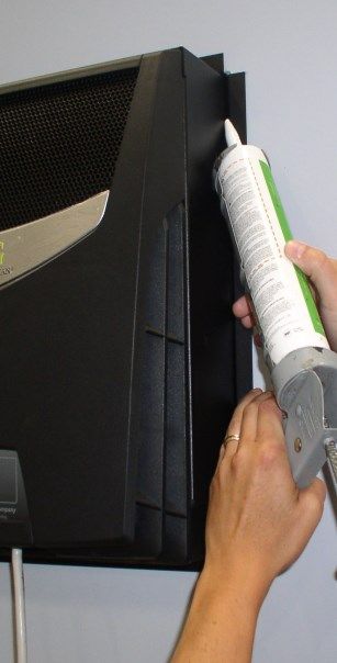
English
                   1. Prepare the wall
                   A. Find wall stud locations on desired wall and mark edg-
                   es of the studs.
                   B. Locate unit height where control can be reached.

                   2. Mark desired location
                   A. Mark hole locations for the TTW EasyMount™ sleeve.
                   Both sides of the wall should be marked for 14½”W x
                   16¼”H (36.8 x 41.3cm) .

                   3. Cut hole in wall
                   A. Cut hole 14½”W x 16¼”H (36.8 by 41.3cm) inside of
                   stud to inside of stud.

                  4. Insert installation sleeve (inside wall-mount sleeve)
                  A. Slide EasyMount™ sleeve into opening so that flange
                  area is flush with finished surface of wall.
                  B. Ensure EasyMount™ sleeve is level and square. Shim
                  bottom and sides as needed.

                5. Fasten sleeve to wall

                A. Insert screws into upper pre-drilled hole on both sides of
                sleeve, continue to lower set of holes. Ensure screws are
                flush with wall sleeve. Do not over tighten.
                  New Design EasyMount™ Sleeve
 The new design EasyMount™ sleeve is fastened through four (4) holes locat-
 ed on either side of its front flange, as shown above.

                 6. Slide unit through installation sleeve
                 A. Slide the Wine Guardian Through-the-Wall system
                 through the Easy Mount™ sleeve. Insert the end of the unit
                 that does not have the power cord attached to it into the
                 sleeve. Then slide the unit into the sleeve until desired
                 depth. Make sure power cord is kept clear of the sleeve.
                                      4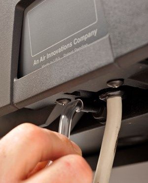
7. Seal the joints
                           A. Seal joint between Wine Guardian Through-the-
                           Wall and EasyMount™ sleeve with latex type sealant
                           to create an air tight installation and prevent horizon-
                           tal movement of the system.
                           B. Install self-adhesive insulation strips to the flange
                           area of the EasyMount™ sleeve to create an adequate
                           thermal block.

                   8. Plug in unit
                   A. Plug unit into dedicated power outlet.

                   9. Condensate Drain
                   CAUTION: DRAIN CONNNECTION ACTION REQUIRED PRIOR TO
                   EQUIPMENT STARTUP
                  Wine Guardian Though-the-Wall units contain an overflow
                  drain port at the base of the condenser (warm air) section of
                  the unit. The over flow drain connection has been left open.
                  See directions below.
A unique feature of the Wine Guardian system is its onboard condensate removal
system which remains always on and acts to boil off excess condensation (water)
from the wine room cooling process. Water will flow out of the overflow port
when excessive moisture is present within the wine room.
A. We suggest you connect the clear plastic tube (included) to the overflow
     port and the other end to a bucket.
B. Monitor the drain port for excessive moisture and empty bucket as needed.
If you consistently have water present from the overflow port you will need to
permanently pipe the drain to an open floor drain, sink, or condensate pump.
If you experience NO water you may wish to remove the plastic drain hose and
install the plastic drain port cover (included).

                   10. Turn unit on
                     At the system’s control panel, press the on/off button twice
                     to turn on. The blue LED next to the power button will illumi-
                     nate. Factory preset temperature is 55 Deg F (13 Deg C). The
                     display will flash the current temperature and humidity as
                     well as show the current temperature with a !.
                     The blue snow flake will be blinking in the bottom right cor-
 ner until a five minute delay has been achieved. The snow flake will then be a
 solid blue color. It will continue to show the current temperature with an ! until
 the temperature in the wine cellar drops below the high temperature alarm set
 point of 65 Deg F (18 Deg C).
 Once the temperature drops below 65 Deg F (18 Deg C), the exclamation point
 will clear and will display the current temperature and humidity.
                                       5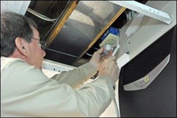
Deutsch
                      1. Die Wand vorbereiten
                      A. Finden Sie einen Platz für die Wandhalterung an der ge-
                      wünschten Wand und markieren Sie die Kanten der Füh-
                      rung.
                      B. Wählen Sie eine Höhe, in der Sie die Bedienelemente
                      erreichen können.

                     2. Markieren Sie den gewünschten Standort
                     A. Markieren Sie den Ausschnitt für die TTW Easymount ™
                     -Wandführung. Beide Seiten der Wand sollten eine Marki-
                     erung von 36,8 cm Breite und 41,3 Höhe cm vorweisen.
                     (14½“ auf 16¼")

                     3. Ein Loch in der Wand ausschneiden
                     Schneiden Sie ein Loch mit den Maßen 36,8 cm Breite auf
                     41,3 cm Höhe (Innenmaße der
                     Wandführung) aus.

                    4. Die Einbauhülse anbringen (Innenwand-Montageführung)
                    A. Schieben Sie die EasyMount™-Wandführung in die Öffnung,
                    sodass der Flanschbereich mit der Oberfläche der Wand bün-
                    dig ist.
                    B. Stellen Sie sicher, dass die EasyMount™-Wandführung eben
                    und quadratisch ist. Passen Sie den Boden und die Seitenwän-
                    de bei Bedarf an.

                  5. Die Führung an der Wand befestigen
                  Befestigen Sie die Schrauben in den oberen Bohrungen auf
                  beiden Seiten der Führung und arbeiten Sie sich nach unten.
                  Stellen Sie sicher, dass die Schrauben bündig mit der
                  Wandführung sind. Überdrehen Sie die Schrauben nicht
                  Neu entworfene EasyMount™-Hülse
 Die neu designte EasyMount™-Wandführung wird mittels der vier (4) Bohrungen ange-
 bracht, die sich, wie oben gezeigt, auf beiden Seiten des vorderen Flansches befinden.

                    6. Schieben Sie die Einheit in die Einbauführung ein
                    A. Schieben Sie das Wine Guardian Wandeinbau-System
                    durch die Easy Mount™-Wandführung. Schieben Sie das
                    Ende der Einheit, an der kein Netzkabel ist, in die
                    Wandführung ein. Dann schieben Sie die Einheit in die
                    Wandführung, bis die gewünschte Tiefe erreicht ist. Stellen
                    Sie sicher, dass das Netzkabel nicht in der Führung ist.

                                          6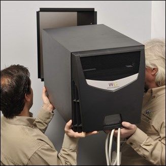
7. Abdichten der Fugen
                            A. Dichten Sie die Fuge zwischen dem Wine Guardian-
                            Wandeinbau-System und der EasyMount™-Führung mit
                            einer Latex-Dichtungsmasse ab, um horizontale Bewegung-
                            en des Systems zu verhindern.
                          B. Installieren Sie selbstklebende Dämmstreifen im Flansch
                          - bereich der EasyMount™-Wandführung, um eine
ausreichende Thermoisolation zu erreichen.

                     8. Anschließen des Gerätes an das Stromnetz

                     A. Schließen Sie das Gerät an eine passende Steckdose an

                     9. Ablassen von Kondenswasser
                     ACHTUNG: VOR DER INBETRIEBNAHME DES GERÄTS, MUSS DER AN-
                     SCHLUSS FÜR DIE KONDENSWASSERABFUHR GEPRÜFT WERDEN
                     Die Wine Guardian-Wandeinbau-Geräte verfügen über einen
                     Überlauf-Anschluss auf der Unterseite des Kondensators
                     (Warmluft) des Geräts. Der Anschluss des Überlaufs wurde offen
                     gelassen. Siehe Anleitung unten. Ein einzigartiges Merkmal des
                     Wine Guardian-Systems ist das eingebaute Kondenswasserabfuhr-
                     System, das immer aktiv ist und auf überschüssiges Kondenswas-
ser im Weinkeller-Kühlsystem reagiert. Es wird Wasser aus dem Überlauf-Anschluss
fließen, sobald überflüssige Flüssigkeit innerhalb des Systems vorhanden ist.
A. Wir empfehlen, dass Sie den klaren Kunststoffschlauch (im Lieferumfang enthalten)
an dem Überlauf anschließen und das andere Ende in einem Eimer platzieren.
B. Überprüfen Sie die Ablauföffnung auf übermäßige Feuchtigkeit und leeren Sie den
Eimer bei Bedarf.
Wenn ständig Wasser aus dem Überlaufanschluss läuft, müssen Sie einen fest instal-
lierten Schlauch zu einem offenen Bodenablauf, einem Waschbecken oder einer Kon-
densatpumpe anbringen.. Wenn KEIN Wasser vorhanden ist, können Sie den Kun-
ststoffablaufschlauch möglicherweise entfernen. Bringen Sie die Öffnungsabdeckung
am Kunststoffablauf an (im Lieferumfang enthalten).

                          10. Die Einheit einschalten
                          Drücken Sie zweimal die Ein-/Aus-Taste auf dem Bedienfeld
                          des Systems, um die Einheit einzuschalten. Die blaue LED
                          neben der Power-Taste leuchtet. Die voreingestellte Temper-
                          atur beträgt 13 °C (55 °F). Auf dem Display blinkt die aktuelle
                          Temperatur und die Luftfeuchtigkeit sowie die aktuelle Tem-
                          peratur werden mit einem "!" angezeigt. Die blaue
                          Schneeflocke in der rechten unteren Ecke blinkt für einen
                          Zeitraum von fünf Minuten. Danach ist die Schneeflocke kon-
                          stant blau. Auch wird weiterhin die aktuelle Temperatur mit
                          einem "!" angezeigt, bis die Temperatur im Weinkeller unter
 die Temperatur fällt, die als Alarmsollwert auf 18 °C (65 °F) eingestellt ist. Fällt die
 Temperatur unter 18 °C (65 °F), wird das Ausrufezeichen gelöscht und die aktuelle
 Temperatur und Luftfeuchtigkeit werden angezeigt .

                                            7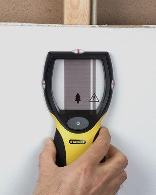
Español
                      1. Prepare la pared

                      A. Busque el tabique en la pared deseada y marque los bordes.

                      B. Localice la altura correcta.

                      2. Marque la localización deseada
                      A. A. Marque los agujeros en los que irá el manguito TTW
                         EasyMount™. Ambos lados de la pared deben estar marca-
                         dos con una distancia de 14½" de anchura por 16¼" de altu-
                         ra. (36,8 por 41,3 cm)

                      3. Haga el agujero en el muro

                      A. Haga un agujero de 14½" de anchura por 16¼" de altura (del
                      interior del tabique al interior del tabique)

                     4. Inserte el manguito de instalación (dentro del manguito de
                     montaje)
                     A. Deslice el manguito de montaje fácil EasyMount™ de forma
                     que el área de las bridas se ajuste a la superficie de la pared
                     terminada.
                     B. Asegúrese de que el manguito EasyMount™ esté bien nive-
                     lado y encuadrado. Ajuste el bajo y los laterales en caso de que
                     sea necesario.

                   5. Ajuste el manguito a la pared
                   A. Inserte los tornillos en el agujero superior pretaladrado en am-
                   bos lados, continúe con los agujeros inferiores. Asegúrese de que
                   los tornillos estén alineados. No los apriete demasiado.
                   Nuevo diseño del manguito EasyMount™
  El nuevo diseño del manguito EasyMount™ se ajusta a través de cuatro (4) agujeros
  situados a cada lado de la brida frontal, como se puede ver arriba

                    6. Deslice el aparato a través del manguito de instalación
                    A. Deslice la bodega refrigerada Wine Guardian ® a través del
                    manguito de montaje Easy Mount™. Inserte el extremo de la
                    unidad sin cable de alimentación dentro del manguito. Después,
                    deslice la unidad por el manguito a la profundidad deseada.
                    Asegúrese de que el cable queda por fuera del manguito.
                                            8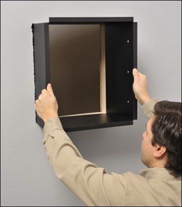
7. Selle las juntas
                              A. Selle las juntas entre la bodega refrigerada Wine
                              Guardian ® y el manguito EasyMount™ con el sellador de
                              látex para conseguir una instalación hermética y preve-
                              nir movimientos horizontales del sistema.
                              B. Instale las bandas de aislamiento autoadhesivas en el
                              área de la brida del manguito EasyMount™ para crear un
                              bloqueo térmico adecuado.

                     8. Conecte la unidad

                     A. Conecte el aparato al enchufe.

                     9. Drenaje condensado
                     ATENCIÓN: ES NECESARIO CONECTAR EL SISTEMA DE DRENAJE
                     ANTES DE ENCENDER EL EQUIPO
                     Wine Guardian ® cuenta con una salida para evacuar el exceso de
                     líquido en la base del condensador (aire caliente). La conexión
                     para la salida del líquido en exceso tiene que estar abierta.
                     Le presentamos las instrucciones a continuación:
Una característica única del sistema Wine Guardian es su sistema integrado para la
eliminación de la condensación, que siempre permanece encendido y actúa evaporan-
do el exceso de la condensación (agua) de la cámara en la que se lleva a cabo la refrig-
eración del vino. El agua saldrá por el puerto de escape.
A. Le aconsejamos que conecte el tubo de plástico (incluido) al puerto de escape y
deje el otro extremo en un cubo.
B. Controle la cantidad de liquido drenado, en caso de que haya demasiada humedad,
vacíe el cubo cuando sea necesario.
Si hay agua saliendo constantemente por el puerto de escape necesitará conectar una
tubería de drenaje permanentemente a una zona abierta, una pila, o una bomba de
condensación. Si NO hay agua, tal vez debería quitar el plástico del tubo de drenaje y
Instalar la cubierta de plástico del puerto de drenaje (incluido)
                          10. Enchufar la bodega refrigeradora
                          Apriete el botón “on/off” en el panel de control del sistema
                          dos veces para encenderla. La luz LED azul al lado del botón
                          de encendido se iluminará. La temperatura predeterminada
                          por el fabricante es 55 °F (13°C) La pantalla mostrará la tem-
                          peratura y la humedad así como la temperatura actual con
                          un !.
                            El copo de nieve azul parpadeará en la esquina inferior a la
                           derecha de la pantalla hasta pasados cinco minutos. Entonc-
 es, la luz del copo de nieve se volverá fija y de color azul. La temperatura actual con-
 tinuará mostrándose con un signo ! hasta que la temperatura en la bodega sea inferi-
 or a la temperatura establecida como temperatura de alarma, que es de 65°F (18°C)
 Una vez que la temperatura sea inferior a 65°F (18°C), el signo de exclamación de-
 saparecerá y aparecerá la temperatura y humedad actual.

                                            9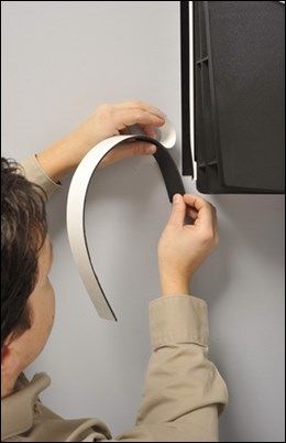
Français
                      1. Préparation du mur
                      A. Déterminez l’emplacement des montants du mur con-
                      cerné et marquez les contours de ces derniers.
                      B. Marquez l'emplacement de l'unité à la hauteur qui vous
                      permettra d'atteindre le panneau de commande.

                      2. Marquage de l’emplacement désiré
                      A. Marquez les emplacements des trous pour la fixation
                      du cadre traversant EasyMount™. Faites une marque des
                      deux côtés du mur d'une dimension de 36,8 cm par
                      41,3 cm (14½" x 16¼")

                      3. Perçage du trou dans le mur
                      A. Découpez un trou de 36,8 cm par 41,3 cm (distance en-
                      tre les deux bords intérieurs des
                      montants).

                     4. Insertion du cadre d'installation (cadre mural interne)
                     A. Glissez le cadre EasyMount™ dans l'ouverture de manière
                     à ce que la bride
                     soit bien en contact avec la surface finie du mur.
                     B. Assurez-vous que le cadre EasyMount™ soit de niveau et
                     à l'équerre. Placez des cales sur le fond et les côtés de l’en-
                     cadrement au besoin.

                   5. Fixation du cadre au mur
                   A. Insérez des vis dans les trous prépercés supérieurs de
                   chaque côté du cadre, et faites de même avec les trous inféri-
                   eurs. Assurez-vous que les têtes des vis soient vissées au ras
                   du cadre mural. Ne serrez pas les vis de manière excessive.
                   Nouveau modèle de cadre EasyMount™
  Le nouveau modèle de cadre EasyMount™ est fixé grâce à quatre (4) trous situés de
  chaque côté de la bride frontale, comme illustré ci-dessus.

                    6. Placement de l’unité dans le cadre d’installation
                    A. Glissez le système de climatiseur traversant Wine
                    Guardian dans le cadre Easy Mount™. Introduisez la partie
                    de l’unité dépourvue de cordon d'alimentation dans le
                    cadre. Ensuite, poussez l’unité dans le cadre à la
                    profondeur désirée. Assurez-vous que le cordon d'alimen-
                    tation soit dégagé du cadre.

                                         10
7. Scellement des joints
A. Scellez les joints entre le climatiseur traversant Wine
Guardian et le cadre Easy Mount™ à l'aide de mastic latex
pêcher que le système ne se déplace horizontalement.
B. Installez des bandes isolantes adhésives au niveau de
la bride du cadre EasyMount™ pour créer une isolation
thermique adaptée.
8. Branchement de l'unité
A. Branchez l’unité à une prise de courant dédiée.
9. Tuyau d’évacuation des condensats
ATTENTION : RÉALISEZ LE RACCORDEMENT DU TUYAU
D'ÉVACUATION AVANT DE METTRE L'APPAREIL EN SER-
VICE
Les climatiseurs traversants Wine Guardian sont dotés d'un
orifice de trop-plein à la base du condenseur (air chaud) de
l’unité. L'orifice de trop-plein a été laissé ouvert. Reportez-
vous aux instructions ci-dessous. La grande particularité du
climatiseur Wine Guardian est son système d’élimination des condensats in-
tégré, en permanence activé, et permettant l'évaporation de l'excès de con-
densation (eau) engendré par le processus de refroidissement de la cave à
vin. Lorsqu’il y a trop d’humidité dans la cave à vin, l’eau s’écoule par l'orifice
de trop-plein. Nous vous suggérons de raccorder l'une des extrémités du
tube en plastique transparent fourni à l'orifice de trop-plein et de placer l’au-
tre extrémité dans un seau. Contrôlez l'orifice de trop-plein à la recherche
d'une humidité excessive et videz le seau si nécessaire. Si de l’eau s'écoule
constamment de l'orifice de trop-plein, il vous faudrale raccorder de manière
définitive à une évacuation au sol, à un évier ou à une pompe à condensats. Si
AUCUNE eau ne s'écoule de l'orifice de trop-plein, vous pouvez éven-
tuellement retirer le tuyau d'évacuation en plastique et installez le cache de
l'orifice de trop-plein en plastique (inclus)
10. Mise en service
Appuyez deux fois sur le bouton marche / arrêt se
trouvant sur le panneau de commande du climatiseur
pour l’allumer. La LED bleue à côté du bouton d'ali-
mentation s’allume. Le préréglage d'usine de la tempé-
rature est de 13 °C (55 °F). L'écran indique la tempé-
rature et l'humidité actuelle. La température actuelle
est suivie de « ! ». Le flocon de neige bleu clignote
dans le coin inférieur droit pendant les cinq premières
minutes avant de cesser de clignoter. L’écran indiquera
la température actuelle suivie de « ! » jusqu’à ce que la température de la
cave à vin soit inférieure à la valeur de consigne de l'alarme de température
élevée, c'est-à-dire 18 °C (65 °F). Une fois que la température est inférieure à
18 °C (65 °F), le point d’exclamation disparaît et seules la température et l’hu-
midité actuelles sont affichées.
11Italiano
1. Preparare la parete
A. Trovare la posizione delle asti di legno nel muro su
cui si intende lavorare e segnarne i limiti.
B. Individuare l'unità d'altezza su cui è possibile
effettuare il controllo
2. Segnare la posizione desiderata
A. Segnare la posizione del foro per il manicotto TTW
EasyMount™ . Entrambe le facciate del muro dovreb-
bero essere segnate per un foro di 36.8 cm L x 41.3cm
3. Praticare un foro nel muro
A. Praticare un foro di 36.8 cm x 41.3 cm (tra un’asta e
l’altra).
4. Inserire il manicotto (manicotto a muro)
A. Infilare il manicotto EasyMount™ nell’apertura
cosicché l’area della flangia sia a livello della superficie
levigata del muro.
B. Assicurarsi che il manicotto EasyMount™ sia livellato e
quadrato. Livellare la base e i lati se necessario.
5. Fissare il manicotto al muro
Inserire le viti nei fori superiori già perforati su entrambi i
lati del manicotto, continuare con la serie inferiore di fori.
Assicurarsi che le viti siano a livello con il manicotto nel mu-
ro. Non serrare eccessivamente.
Nuovo modello di Manicotto EasyMount™
Il nuovo modello di manicotto EasyMount™ è fissato attraverso quattro (4)
fori posizionati su entrambi i lati della flange anteriore, come mostrato sopra
6. Infilare l’unità attraverso il manicotto
Infilare il sistema a muro Wine Guardian attraverso il
manicotto EasyMount™. Inserire la estremità finale
dell’unità nel manicotto senza che il cavo di alimenta-
zione sia collegato ad essa. Quindi infilare l’unità nel
manicotto fino alla profondità desiderata. Assicurarsi
che il cavo di alimentazione sia lontano dal manicotto.
127. Sigillare i giunti
A. Sigillare i giunti tra il Wine Guardian ad incasso e il
manicotto EasyMount™ con sigillante in lattice per
creare un’installazione ermetica e prevenire il mo-
vimento orizzontale del sistema.
B. Installare le strisce isolanti autoadesive sull’area
della flange del manicotto EasyMount per creare un adeguato isolamen-
to termico.
8. Collegamento unità
A. Collegare l’unità all’apposita presa elettrica
9. Tubo drenaggio condensa
ATTENZIONE: COLLEGARE IL TUBO DI DRENAGGIO PRIMA
DELL’AVVIO DELL’IMPIANTO
Le Unità ad incasso Wine Guardian sono dotate di un foro
per il drenaggio alla base del condensatore (di aria calda)
dell’unità. Il foro per il drenaggio dev’essere lasciato aper-
to. Vedere istruzioni sottostanti.
Una caratteristica peculiare del sistema Wine Guardian è il sistema di
rimozione della condensa incorporato che rimane sempre attivo e fa evapo-
rare la condensa (di acqua) in eccesso dovuta al processo di raffreddamento
del vino. L’acqua defluirà dal foro di drenaggio quando l’umidità nella cantina
raggiunga un livello troppo elevato.
E’ consigliato collegare il tubo di plastica trasparente (in dotazione) al foro di
drenaggio e posizionare l’altra estremità in un secchio. Monitorare il foro di
drenaggio qualora il livello di umidità diventi troppo elevato e svuotare il sec-
chio se necessario. Se dal foro di drenaggio fuoriesce costantemente
dell’acqua dovrete collegare in maniera permanente il tubo di drenaggio ad
un tombino, ad un lavabo, o ad una pompa per condensa.
Se NON fuoriesce acqua potreste voler rimuovere il tubo di drenaggio di plas-
tica e Installare il coperchio della porta di scarico di plastica (includo)
10. Accendere l’unità
Premere il tasto on/off due volte sul pannello di controllo del
sistema per accenderlo. La luce LED di colore blu accanto al tasto
di accensione si illuminerà. La temperatura di fabbrica preim-
postata è di 13°C (55 F). Il display mostrerà la temperatura e l’u-
midità così come l’attuale temperatura seguita da un punto
esclamativo (!).
Il fiocco di neve azzurro nell’angolo in basso a destra lampeggerà
per circa cinque minuti. Successivamente sarà di un colore azzur-
ro continuo. Il display continuerà a mostrare la temperatura attuale seguita da un
punto esclamativo (!) fino a che la temperatura della cantina non scenderà sotto il
punto massimo di regolazione della temperatura di 18°C (65 F). Una volta che la tem-
peratura sarà scesa sotto i 18°C, il punto esclamativo sparirà e apparirà l’attuale tem-
peratura e umidità.
13Nederlands
1. Bereid de muur voor
A. Lokaliseer de balken in de gewenste wand en markeer
de randen van de balken.
B. Bepaal de hoogte van het apparaat zodat u nog bij de
bediening kunt
2. Markeer de gewenste locatie
A. Markeer de plaatsen van de gaten voor de TTW
EasyMount™ montagebeugel. Beide zijden van de wand
moeten worden gemarkeerd voor 36,8cm bij 41,3cm
(14½" x 16¼" H).
3. Maak een opening in de wand
A. Maak een opening van 14½” B x 16¼” H (binnenkant
balk naar binnenkant balk).
4. Plaats montagebeugel (in de wandmontage)
A. Schuif de EasyMount™ beugel in de opening zodat de
flensvlakken niet buiten de wandafwerking uitsteken.
B. Zorg dat de EasyMount™ beugel horizontaal en vier-
kant is. Vul onder- en zijkanten op indien nodig.
5. Bevestig de beugel aan de wand
A. Plaats schroeven in de bovenste voorgeboorde gaten aan
weerszijden van de beugel. Doe dit vervolgens ook bij de
onderste gaten. Zorg dat de schroeven niet buiten de beugel
steken. Draai niet te vast.
Nieuw ontwerp EasyMount™ beugel
De nieuw ontworpen EasyMount™ beugel wordt bevestigd door vier (4)
gaten die zich aan elke kant van de voorflens van de beugel bevinden, zie
hierboven
6. Schuif het apparaat door de installatiebeugel
A. Schuif het Wine Guardian door-de-muur systeem door
de Easy Mount™ beugel. Plaats de kant van het apparaat
waar het netsnoer zich niet bevindt, in de beugel. Schuif
het apparaat daarna in de beugel tot de gewenste diepte
is bereikt. Zorg ervoor dat het netsnoer vrij blijft van de
beugel.
147. Dicht de naden
A. Dicht de naad tussen de Wine guardian door-de-
muur en de Easymount™ beugel met een latex kit om
een luchtdichte installatie te verkrijgen en horizonta-
le beweging van het systeem te voorkomen.
B. Plaats zelfklevende isolatiestrips op de
flensvlakken van de EasyMount™ beugel om een
afdoende thermische isolatie te verkrijgen.
8. Sluit het apparaat aan
A. Sluit het apparaat aan op een special toegewezen stop-
contact.
9. Condensafvoer
OPGEPAST: AFVOER AANSLUITING NOODZAKELIJK VOOR-
DAT HET APPARAAT WORDT GESTART
De Wine Guardian door-de-muur eenheden hebben een
overloopafvoer aan de onderkant van de condensor (warme
lucht) zijde van het apparaat. De overloopafvoer is open
gelaten. Zie onderstaande aanwijzingen.
Een unieke eigenschap van het Wine Guardian systeem is
het ingebouwde condensverwijderingssysteem dat altijd aan blijft staan en
overtollig condens (water) van het wijnkelder-koelproces uitkookt. Water zal
uit de overloop stromen wanneer er zich veel vocht in de wijnkelder bevindt.
A. We raden aan om de heldere kunststof slang (meegeleverd) aan te sluiten
op de overloop en het andere einde in een emmer te hangen.
B. Hou de afvoer in de gaten en leeg de emmer indien nodig.
Als er steeds water uit de afvoer blijft komen, dient u de afvoer permanent op
de riolering, een spoelbak of een condenspomp aan te sluiten. Als er GEEN
water uit de afvoer komt, kunt u de kunststofslang verwijderen en installeer
de kunststof afvoer-afdekking (meegeleverd)
10. Zet het apparaat aan
Druk de aan/uit knop op het bedieningspaneel van het
apparaat twee keer in om in te schakelen. De blauwe LED
naast de aan/uit knop zal oplichten. De in de fabriek in-
gestelde temperatuur is 13 graden C (55 graden F). Op het
scherm zal de huidige temperatuur en vochtigheid te zien
zijn en tevens zal de huidige temperatuur met een !
worden weergegeven. De blauwe sneeuwvlok
rechtsonder zal knipperen totdat de vijf minuten wachttijd verstreken zijn. De
sneeuwvlok zal dan continu blauw gaan branden. De huidige temperatuur
blijft aangegeven met een ! totdat de temperatuur in de wijnkelder daalt tot
onder de alarmgrens van 18 graden C (65 graden F). Zodra de temperatuur
daalt tot onder 18 graden C (65 graden F), zal de uitroepteken verdwijnen en
de huidige temperatuur en vochtigheid weergegeven worden.
15中文
1.准备好墙面
A. 在要安装本系统的墙上找到墙柱位置,做好标记。
B. 确定好设备高度,以便控制装置连接。
2.标记位置
A. 为TTW EasyMount™套筒标出孔洞位置。
墙壁两边应该标出14½"宽x16¼"高。(36.8乘41.3厘
3.在墙上开孔
A. 开孔尺寸为14½"宽x16¼"高(墙柱内侧到墙柱内
侧)。
4.插入安装套筒(内壁安装套筒)
A.将EasyMount™套筒滑入墙壁开孔,以便凸缘可以与
光洁的墙面齐平。
B.确保EasyMount™套筒不倾斜,呈正方形。底部和侧
面需要放置填隙片。
5.将套筒固定在墙壁上
A. 将螺丝拧入套筒两侧上部预先钻好的孔内,
然后再拧入下部的孔内。确保螺丝与套筒齐平。不要拧得过
紧。
全新设计的EasyMount™套筒
全新设计的EasyMount™套筒,前凸缘两侧各有四(4)个孔可以用来固定套
筒,如上图所示
6.将设备滑入安装套筒内
A. 将穿墙式酒类保护系统滑入安装套筒内。将尚未连接电源
的设备的一端放入套筒。然后滑进套筒,到达指定深度。确
保电源线不接触套筒。
167.对接缝处进行密封
A. 对穿墙式酒类保护系统和EasyMount™套筒之
间的接缝处用乳胶类密封剂进行密封。实现气密
安装,防止系统水平移动。
B. 在EasyMount™套筒的凸缘区域安装自粘性绝
缘条,以便充分隔热。
8.设备接通电源
A. 将设备插在专用的插座上。
9.冷凝水排水管
注意:需要在设备启动之前连接好排水管
穿墙式酒类保护设备的冷凝器部分(热空气)的底部,
有一个溢流口。溢流口保持敞开状态。
见下面说明。
本系统的一个独家功能就是独立冷凝水排出系统,可以始终敞开状态,
汽化掉酒窖冷却过程中过量的冷凝水(水)。如果酒窖内有过多的水
分,水可以从溢流口流出。
A. 我们建议用透明塑料管连接溢流口(插入),塑料管的另一端放在水
桶中。
B. 查看排水孔是否有过多水分,需要时清空水桶。如果总是发现溢流口
有水,需要用管子长期将排水口与开放式地漏、水槽或冷凝泵连接。如
果您发现溢流口没有水,可以拔掉塑料管 安装排水口塑料盖(包括)
10.启动设备
按设备控制面板上的on/off按钮两次,就可以启动
设备。之后,电源按钮边上的蓝色LED灯将亮起。
设备出厂时预先设置的温度为55华氏度(13摄氏
度)。显示屏将闪现当前温度、湿度,并显示当前
温度带!号。
5分钟延迟到达之前,右下角的蓝色雪花将闪烁不
停。然后,雪花将变成实心蓝色。显示屏将继续显示当前温度带!号,
直到酒窖温度低于65华氏度(18摄氏度)的高温设定值。
温度低于65华氏度(18摄氏度)后,!号将消失,显示当前温度和湿
度。
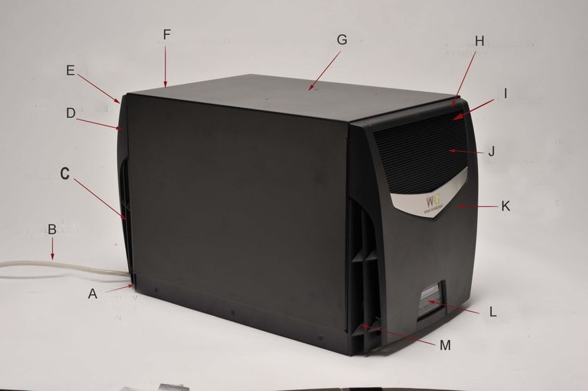
17English Deutsch
A. ANSCHLUSS DES
A. CONDENSATE OVERFLOW CON-
KONDENSWASSERÜBERLAUFS
NECTION AT BASE OF CONDEN-
AN DER UNTERSEITE DES
SER SECTION
KONDENSATORELEMENTS
B. POWER CORD B. NETZKABEL
C. AIR INTAKE C. LUFTEINLASS
D. REMOVABLE FACE PLATE D. ABNEHMBARE FRONTPLATTE
E. AUSLASS WARME LUFT
E. WARM AIR DISCHARGE
F. KONDENSATORELEMENT
F. CONDENSER SECTION
G. GEHÄUSE
G. CABINET
H. VERDAMPFERELEMENT
H. EVAPORATOR SECTION I. AUSLASS KALTE LUFT
18
I. COLD AIR DISCHARGE J. GERICHTETE LÜFTUNGSSCHLITZE
HINTER DER FRONTPLATTE
J. DIRECTIONAL LOUVERS BEHIND
FACE PLATE K. ABNEHMBARE FRONTPLATTE
K. REMOVABLE FACE PLATE L. INTEGRIERTES BEDIENFELD
M. LUFTEINLASS
L. INTEGRATED CONTROL PANEL
M. AIR INTAKEEspañol Français Italiano Nederlands Chinese
A. Exceso de concentración en A. RACCORD DU TROP-PLEIN DE A. FORO PER IL DRENAGGIO A. AANSLUITING A. 冷凝器底座的冷凝液溢
la conexión en la base del CONDENSATS À LA BASE DU ALLA BASE DEL CONDENSOVERLOOP
流连接
condensador. CONDENSEUR CONDENSATORE ONDERAAN
CONDENSORGEDEELTE B. 电源线
B. Cable B. CORDON D’ALIMENTATION B. CAVO DI ALIMENTAZIONE
B. NETSNOER
C. Entrada de aire C. ENTRÉE D’AIR C. PRESA D’ARIA C. 进气口
C. LUCHTINLAAT
D. Placa frontal extraíble D. FAÇADE AMOVIBLE D. COPERTURA ANTERIORE D. 可拆卸面板
RIMOVIBILE D. VERWIJDERBARE
E. Emisión de aire caliente E. SORTIE D’AIR CHAUD E. 暖风出口
VOORPLAAT
E. FUORIUSCITA DI ARIA CALDA
F. Condensador F. ZONE DU CONDENSEUR E. WARME LUCHTUITLAAT F. 冷凝器
F. CONDENSATORE
G. Armario G. ARMOIRE F. CONDENSORGEDEELTE G. 机柜
G. ARMADIETTO
19
H. Evaporador H. ÉVAPORATEUR G. KAST
H. EVAPORTATORE H. 蒸发器
I. Emisión de aire frío I. SORTIE D’AIR FROID H. VERDAMPERGEDEELTE
I. FUORIUSCITA DI ARIA FRED- I. 冷风出口
J. Rejillas direccionales detrás J. VOLETS ORIENTABLES DERRIÈRE DA I. KOUDE LUCHTUITLAAT
de la placa frontal LA FAÇADE J. 面板后面的导向百页窗
J. ALETTE DIREZIONALI DIETRO J. RICHTBARE
K. Placa frontal extraíble K. FAÇADE AMOVIBLE 板
LA COPERTURA ANTERIORE VENTILATIEKLEPPEN ACHTER
L. Panel de control integrado VOORPLAAT
L. PANNEAU DE COMMANDE IN- K. COPERTURA ANTERIORE K. 可拆卸面板
TÉGRÉ RIMOVIBILE K. VERWIJDERBARE
M. Entrada de aire
L. 集成式控制面板
VOORPLAAT
M. ENTRÉE D’AIR L. PANNELLO DI CONTROLLO
INTEGRATO L. GEÏNTEGREERD M. 进气口
BEDIENINGSPANEEL
M. PRESA D’ARIAThrough-the-Wall
Quick Start Installation Guide
U. S. Headquarters
7000 Performance Drive
North Syracuse, New York
USA 13212
+1 315-452-7400
www.wineguardian.com
info@wineguardian.com
European Office
Wine Guardian GmbH
Pestalozzistrasse 2
CH 8201 Schaffhausen
Switzerland
+41 52 224 0490
To download Wine Guardian Through-the-Wall System
Operations and Installation manual
Follow this short link
http://bit.ly/1To1yB8
Part No. 15H0155-01 REV. 02-2016
20You can also read