Topology Optimisation Influence on Architectural Design Process - Cumincad
←
→
Page content transcription
If your browser does not render page correctly, please read the page content below
Topology Optimisation Influence on Architectural Design
Process
Enhancing Form Finding Routine by tOpos Toolset utilisation

                Sebastian Bialkowski1
                1
                  Lodz University of Technology
                1
                  sebastian.bialkowski@p.lodz.pl

                The paper focuses on possibilities of already known engineering procedures such
                as Finite Element Method or Topology Optimisation for effective implementation
                in architectural design process. The existing attempts of complex engineering
                algorithms implementation, as a form finding approach will be discussed. By
                intersecting architectural form evaluation with engineering analysis
                complemented by optimisation algorithms, the new quality of contemporary
                architecture design process may appears.

                Keywords: topology optimisation, design support tools, complex geometries,
                General Programing GPU, CUDA

INTRODUCTION                                           ing layout meets a prescribed set of performance tar-
Fast spreading of generative and parametric tech-      gets. It could be implemented through the use of Fi-
niques allows to extend existing design procedures     nite Element Methods (FEM or FEA) for the analysis
including form finding process with additional as-      and a variety of optimization techniques such as the
pects. Architects are looking for new approaches       Method of Moving Asymptotes, Genetic Algorithms,
which may support that process with new and            the Optimality Criteria method, Level Sets or Topo-
unique solutions for particular problem. Amalga-       logical Derivatives. Topology optimisation algorithm
mate of architects’ design experience and precise      is very widely used in the industrial product design
engineering tools through generative design proce-     such as aerospace and automotive where mechanical
dures, can bring new and undiscovered forms into       parts efficiency and its material usage is crucial. Also
contemporary architecture.                             Civil Engineering is not lagging in this field (Guest
                                                       and Moen 2010). Many scientific discourse and re-
BACKGROUND                                             searches have been made, implementing Structural
As an extraordinary utility in the architectural de-   Optimisation for various purposes. Nevertheless,
sign practice, topology optimisation methods might     topology optimisation as an engineering tool is rarely
be pointed. On it bases, topology optimisation is a    applied in the architectural design process. Com-
mathematical approach that optimises material lay-     monly it is caused by a complex and time taking pro-
out within a given design space, for a given set of    cess to achieve results which would satisfy a designer.
loads and boundary conditions, such that the result-        Existing architectural adaptation of topology op-

                                   APPLICATIONS IN CONSTRUCTION & OPTIMISATION - Volume 1 - eCAADe 36 | 139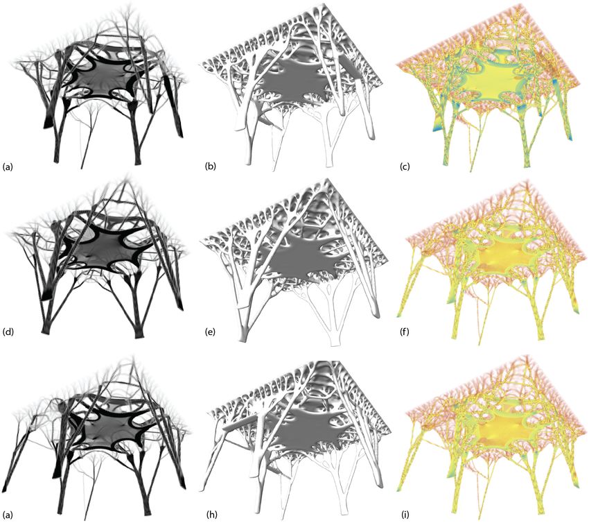
Figure 1
                                                                                                                    tOpos workflow
                                                                                                                    based on icons.

   timisation are the result of deep research and time       Processing Units) technology.
   consuming experiments often aided by specialists in
   Civil Engineering. The tools applied for that projects    TOPOS - GPU ACCELERATED PLUGIN
   are either highly specialised and expensive engineer-     Creation of new tools, adjusted to the nowadays per-
   ing software or individually developed toolsets for       formance requirements, enforces a software devel-
   current problem. However, general purpose engi-           oper to use always up-to-date technologies. Topol-
   neering programs available on the market contain-         ogy optimization as a material distribution method
   ing Structural Optimisation algorithms, except of the     based on a numerical approach can be success-
   cost, has many additional limitation which decrease       fully enhanced by a contemporary computing tools.
   a possibility of usage those methods by architects for    Based on scientific researches (Schmidt and Schulz
   enriching their design process. Their explicit user in-   2011) authors came up with an idea of developing
   terface and moreover, plethora of options and deci-       and implementing own topology optimization algo-
   sions which user has to make, put it as a highly speci-   rithm enhanced with the GPU acceleration which
   fied software dedicated to the limited range of users.     may speed up calculation process up to 160 times.
        All presented arguments affirm the author about        The aim of the author research is to create a form
   the need for developing a new tool for designers. It is   finding real-time tool for an architects based on the
   highly intended to give the opportunity to variety of     engineering Structural Optimisation Methods. As a
   architects and designers to use the exceedingly com-      main theorem, Simple Isotropic Microstructure with
   plex and compound process to improve their designs        Penalisation (SIMP) method developed by Bendsøe
   without any specialised knowledge. Complementary          and Sigmund (Bendsøe and Sigmund 2004) was cho-
   to the described application of Structural Optimisa-      sen.
   tion method in architecture, author will present a             The project, named “tOpos”, unlike the compli-
   new approach concerning form finding tool based on         cated and expensive commercial tools for engineers
   Topology Optimisation algorithm accelerated with          is meant to be simpler, faster and more efficient. The
   the GPGPU (General Purpose computing on Graphics          basic environment for tOpos is Rhinoceros3D soft-

140 | eCAADe 36 - APPLICATIONS IN CONSTRUCTION & OPTIMISATION - Volume 1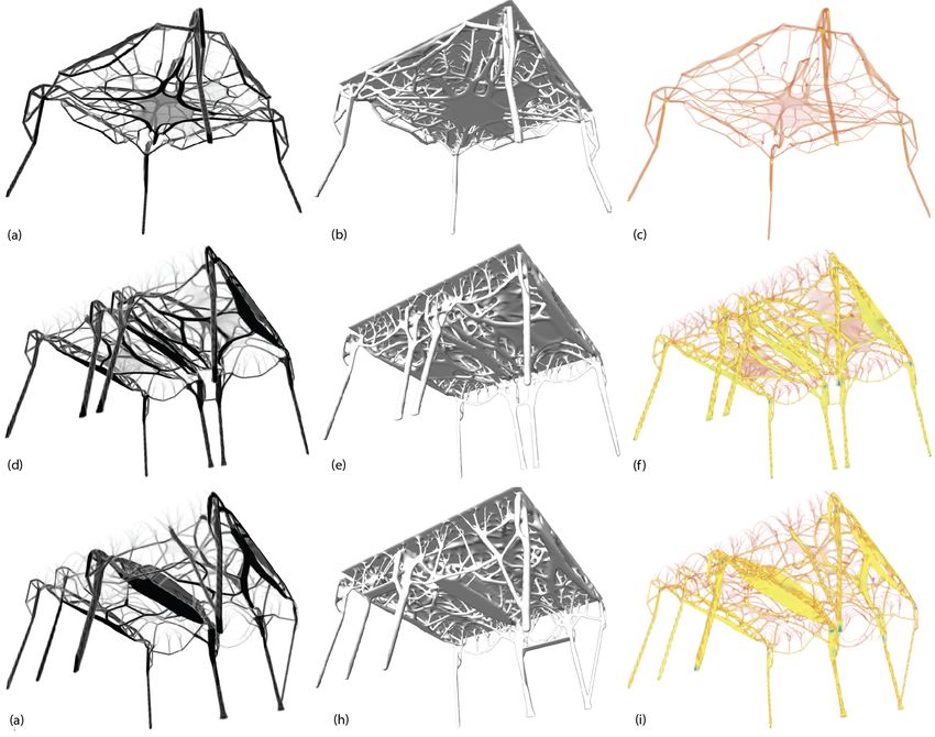
ware with the Rhinocommon libraries. The McNeel            iterations. For penalty factor, continuity method was
software is used as a 3D engine for data display and       utilised (Bendsøe and Sigmund 2004, p. 22), where
what is more, as a modelling environment necessary         in the beginning the value is equal to 2.0 and rises
for the algorithm to create input data. tOpos also         through iteration to reach value of 3.0 on the end of
utilises Rhinocommon library to process meshes and         the process. Also filtering of sensitivity was applied
vectors. The plugin core is based on the host code         with constant radius equal to 1.5 element size. Aim of
(performed on CPU) implemented on DotNet C# with           the optimisation was to remove maximum amount of
acceleration kernels (performed on GPU) based on           the material by minimizing structure compliance in
the CUDA API (Sanders et al. 2012), the extension of C     the same time. Due to the architectural nature of the
language. Interconnection between CUDA C and C#            research, great emphasis was placed on presenting
is managed by 1:1 wrapper named managedCUDA                the results of tests in a legible manner in relation to
developed by Michael Kunz, which allows to use pure        the obtained forms. Main data generated by tOpos is
CUDA API without losing computational power and            the material density distribution in space for each el-
functionality. The GPGPU allows to exploit parallel ar-    ement represented as point cloud. The colour scale
chitecture pipeline to bring a new approach to a real      was selected for intuitive readability: black repre-
time application.                                          sents full material (density of 1.0) and white refers
                                                           to void spaces (the density equal to 0.0). Those data
TOPOS - INFLUENCE ON ARCHITECTURAL                         might be also represented as a volume object by util-
                                                           ising marching cube algorithm (Lorensen and Cline
DESIGN
                                                           1987) which creates boundary surface by evaluating
Numerical benchmarks (Bialkowski 2017) prove fast
                                                           scalar fields called isosurface. Due to the numerical
and reliable results of topological optimisation im-
                                                           aspect of the method, apart from the forms obtained
plemented as a tOpos toolset. This allows to perform
                                                           with the use of isosurface, additionally the compli-
the sets of experiments and tests related to the archi-
                                                           ance of elements in the model was presented for
tecture. Basic researches were done in three series as
                                                           each test. For this scheme, the blue colour means
follow:
                                                           the highest deformability of the element, and the
     • Series I - tests 1A,1B and 1C                       red its low coefficient with the intermediate yellow
     • Series II - tests 2A,2B and 2C                      colour. For legible representation of data, the limit
     • Series III - tests 3A,3B and 3C.                    values, such a density or compliance equal to 0.0 are
The series differ on the material availability for topol-   completely transparent. This allows to look at the
ogy optimisation algorithms, but also on support           structure by omitting numerically irrelevant data.
condition or additional restriction like door and win-
dow openings. For all series box like shaped object        Series I
as main material domain was implemented. It is 500         In this part of research, the algorithm has full freedom
cm in length and width with 300 cm in height. In all       in the material allocation inside entire design space.
      2kN                                                  Through three tests, only support conditions or ad-
cases       as an area load was utilises on top face of    ditional openings inside design domain might vary.
       m2
model for imitating typical floor slab.                     The aim of this researches is to check what forms the
                                                           algorithm will return without any spatial restrictions
Optimisation initial conditions and result                 for material distribution.
presentation                                               Test 1A. Initial conditions are presented on figure
Based on the performance benchmarks (Białkowksi            2a. Generated structures in their form resemble the
2017), general optimisation setups were well-              cross-rib vault. However, instead of typical circle
defined. Each tests was optimised by maximum of 40

                                      APPLICATIONS IN CONSTRUCTION & OPTIMISATION - Volume 1 - eCAADe 36 | 141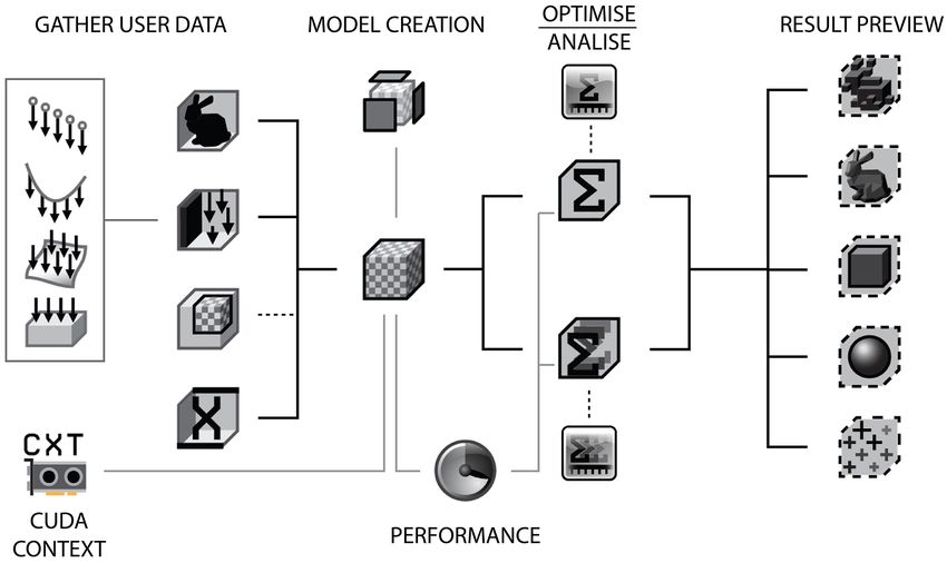
Figure 2
                                                                                                                             Initial conditions for
                                                                                                                             test in series III. a)
                                                                                                                             Test 1A, b) test 1B,
                                                                                                                             c) test 1C.

   based arches, the ribs took the shape of chain or          fixed in the middle part of the support. Those ribs
   parabolic curves. Analysing figure 3a and 3b, it’s easy     splits at an angle of about 45 ° to smaller structures
   to see that the whole structure is hierarchical. In        as they approach the floor slab, forming intermedi-
   other words, the loads set at the top of the material      ate ribbed systems, analogously to the 1A test. In
   domain are not directly transferred to the supports.       the place where the main ribs meet, we can similarly
   Interesting aspect of this structures is the change in     distinguish a vault-like system that creates a rhom-
   the thickness of the ribs along with their subsequent      boid shape, which is clearly visible on figure 3d and
   divisions and distributions. They become thinner           3f. The second topological arrangement consists of
   and finer. It is easy to see the connotations with the      columns structures divide into smaller pieces resem-
   construction of a tree, where the emergence of suc-        bling branches as they approach the floor slab, col-
   cessive branches reduces the diameter of the trunk         lecting the load from a much larger surface. In terms
   and branches. The layout of the ribs is enriched with      of functionality, it is worth noting that this structure
   additional horizontal elements that stiffen the whole       interferes with the design space lesser than the result
   system. Smaller structural systems resembling knit,        of study 1A. Numerically, an equally low volume in-
   collects the load from the larger surface, and then,       dex equal to 2.5% of the material in relation to the ini-
   accumulated, transfer it to the ribs, and those to the     tial volume was reached. The difference between the
   supports. From the architectural point of view, some       previous and the current study is less than 0.5%, but
   details known from classic architecture can be distin-     two different qualities of space has been achieved.
   guished in the structure, for example, a vault key or      Test 1C. Initial conditions are presented on figure 2c.
   ribs resembling a cross-ribbed vault which is clearly      No changes in the support scheme resulted topolog-
   visible in Fig. 3b. However, despite the optimised         ically similar structures comparing to the systems ob-
   amount of material, the structure occupies a rela-         tained in the 1B study. The introduction of additional
   tively large space, which can be exploited by users.       restrictions such a door and window openings with
   Obtained structure is less effective as a living space      the addition of a load at the lintel site, resulted in a de-
   than a typical pillar system.                              formation of the form obtained in the previous study
   Test 1B. Initial conditions are presented on figure 2b.     (Figure 3g). The symmetry of some solutions is still
   Due to the change in the support scheme, the ob-           well legible, but the components, i.e. ribs, are dis-
   tained structures differ significantly from the forms        torted or shifted as a result of adapting to new con-
   obtained in test 1A. The algorithm generated a sym-        straints. In the figure 3h and 3i, can be seen clearly
   metrical structure (Figure 3d), topologically consist-     the main ribs and posts shifts in places where doors
   ing two systems. Both is easily seen by analysing fig-      and windows are placed. In addition to the elements
   ure 3e. The ribs system collecting loads from the mid-     and properties listed in the previous study, it is worth
   dle part of the floor slab. It consists of four main ribs   adding the aspect of adapting a regular, symmetri-

142 | eCAADe 36 - APPLICATIONS IN CONSTRUCTION & OPTIMISATION - Volume 1
Figure 3
Result forms from
series I. From left:
Densities as points,
compliance as
points, forma as
volume. Test 1A fig.
a-c, test 1B fig. d-f
and test 1C fig. g-i .
cal structure to new requirements, such as window Series II
or door openings. The algorithm created additional In this research the algorithm has been strictly limited
structural systems so that subsequent architectural to the possibilities of placing the material in space.
elements would have a chance to appear in structure. Three cases are tested: columns, shell and shell with
Their influence on the form is clearly visible on fig- holes. The research aim is to check what forms the al-
ure 3g. It shows the possibility of adapting the archi- gorithm will generate with strong spatial restrictions
tectural structure to specific requirements defined by on the possibility of material decomposition.
the user. Test 2A. Initial conditions are presented on figure
4a. The optimisation result turned out to be surpris-
ing. A very interesting structure was obtained, tak-
APPLICATIONS IN CONSTRUCTION & OPTIMISATION - Volume 1 - eCAADe 36 | 143Figure 4
Initial conditions for
test in series III. a)
Test 2A, b) test 2B,
c) test 2C.
ing into account its topology and form. Analysing its The combination of these two designs results in a
construction on figure 5a, it could be found a lot of very interesting visual effect. Imposing severe restric-
interesting design solutions. The first are the con- tions on space in which the algorithm could work re-
struction of pillars. As can be seen, the algorithm sulted in obtaining the completely free and undis-
again seek to generate a load-bearing elements in torted structural elements.
the shape of a parabolic, which may provide an ini- Test 2B. Initial conditions are presented on figure
tial course of the post leaning towards the centre, 4b. Changing the support conditions and allowing
referring to the test 1A result shown in Figure 3a. the algorithm to allocate the material in the wall-like
However, due to the limitations in the material allo- space resulted in a topologically different structure
cation space, this shape breaks near half the height compared to the 2A study. However, it is worth not-
of the column and changes into a vertical element. ing a certain repeatability of some construction el-
The torques and the related deformation particularly ements that have been generated. Comparing fig-
close to the floor slab (Figure 5c) necessitated the cre- ure 5a with figure 5d, presenting the currently gen-
ation of additional support in the form of a truss in erated form, it is easy to see a similar arrangement of
the shape of the letter “L”. Two beams with a truss- connection between the column and the slab in the
like structure are added to each of these structures at form of an L-shaped truss. Analysing the whole form
the point of inflection from the inside. They are lo- (Figure 5e), it can be distinguish two basic systems
cated close to the edge of the design space, defining of load-bearing structures: four columns for each of
the sides of the floor slab. In the slab part, the ma- the space of the walls and connecting beams in the
terial is mainly located in its upper and lower part. space of the floor slab. The combination of these two
The space between the central structure of the ceil- elements is well visible in Figure 5d, and its shape
ing and trusses at the edge of the entire domain is from a structural point of view can be associated with
filled with a space lattice, collecting loads and trans- the hinge. The two inner pillars are similar to each
ferring them to the nearest main structural element. other, creating between the end pillars a space in the
They are clearly visible in figure 5b. Their topology shape of aisles. It is also worth noting the differences
resembles a cellular structure, called Voronoi tessel- in the thicknesses of the columns, where the cross-
lation. section of the inner column differs significantly from
The obtained form from the architectural point the corner. Between the main beams, as in test 2A,
of view is rich in a very interesting detail. A large a network of smaller beams, bolts or discs has been
number of small components makes the structure fil- formed, building spatial organic structure, collecting
igree, lace, and gives a sense of lightness. The fi- load of these fields. Similarly to test 2A, the obtained
nal form merges a simple in shape main load-bearing form is rich in detail, mainly because of strong frag-
structure with the organic soft filling between them. mentation of the components. It is worth paying at-
144 | eCAADe 36 - APPLICATIONS IN CONSTRUCTION & OPTIMISATION - Volume 1Figure 5
Result forms from
series II. From left:
Densities as points,
compliance as
points, forma as
volume. Test 2A fig.
a-c, test 2B fig. d-f
and test 2C fig. g-i .
tention to the strongly sculpted form of the bottom Test 2C. Initial conditions are presented on figure 4c.
part of the floor slab shown in figure 5e and 5f. De- The introduction of additional restrictions in the form
spite the great freedom in shaping vertical elements of holes greatly influenced the optimisation effect.
in the wall space, the algorithm generated a system When comparing the results of study 2B in Figure 5d
of columns, which were arranged in a certain rhythm. or 5e, with Figure 5g or 5h from study 2C, differences
It is also worth noting that the appearance of pillars in structures are clear to notice. Rhythmic structure
as the main vertical bearing elements instead of full achieved in the preceding test has been replaced by
walls or shields, allows architects to more freely ar- a form adapted to the new requirements defined by
range the space. The lack of internal structures inter- window and door openings. Corner columns has
fering with the design space that could be observed been moved to the vicinity of the window, which re-
in the result of tests 1A or 1B, additionally increases sulted in a lack of support corner of the floor slab.
the usable value of the obtained spaces. To solve this problem, the column took the shape of
the letter “V” of varying thickness arms. In a similar
APPLICATIONS IN CONSTRUCTION & OPTIMISATION - Volume 1 - eCAADe 36 | 145Figure 6
Initial conditions for
test in series III. a)
Test 3A, b) test 3B,
c) test 3C.
way, a beam connected to this column was gener- proaching the surface of the floor slab are divided
ated. It has adopted a shape of the letter “Y”. The into two smaller branches. To the ends of these ex-
lack of force distribution on the two internal pillars tended pillars in the space of the ceiling slab, com-
resulted in the accumulation of loads of the major plex systems of beams and trusses form a floor slab.
part of the floor slab on one frame. The consequence The lower beams are integrated with each other with
are thicker columns of the middle frame and a larger a thin plate. Between the top of the floor slab and
and more extended beam (figure 5h). A wide span this plate a three-dimensional spatial thruss was cre-
between columns was created on the wall where the ated (Figure 7b). The corners of the board are a sep-
doorway was located, forced the algorithm to create arate arrangement and are supported by diagonal
an additional structure taking over the load from the “V” shaped pillars. They combine additional ribs and
ceiling. Instead of building another pillar, a truss was braces, forming vaults collecting loads from the ceil-
created transferring loads to the adjacent columns. ing.
Looking at the figure of 5i, it can be seen that its low- From the architectural point of view, the algo-
est point is below the level of 200 cm, which may rithm created very unusual forms, very organic and
cause limitations of the space’s usability in this place. symmetrical. Particularly noteworthy is the design of
It is also easy to observe numerous structures resem- the upper and lower floor slabs, consisting of a large
bling branches that collect loads from larger areas of number of arches, forming an almost regular pat-
the slab and transfer them further to larger elements. tern. From these arches, regular rectangular struc-
tures (Figure 7c) move towards the corners divid-
Series III ing the ceiling areas into triangles and quadrangles.
Test 3A. Initial conditions are presented on figure Looking at Figure 7b it is not hard to see a large num-
6a. Adding two extra spaces where the algorithm ber of components which can successfully play the
can handle material resulted in obtaining completely role of architectural detail. Looking at the repetitive
new forms and structures. Analysing the results of arrangement of small branches collecting loads from
densities in Figure 7a, it can be found some inter- the edge of the ceiling, observer can get the impres-
esting design solutions. At the beginning it is worth sion that we are dealing with a roof finial in the form
paying attention to the unusual arrangement of ver- of a decorative cornice. The filigree elements, i.e. the
tical elements in the wall space. Instead of a row previously mentioned twigs, which are numerous in
of columns, as was the case in the study 2B in se- this form, give a great lightness to the whole struc-
ries II, the algorithm generated one complex struc- ture. This effect is further intensified by unusual ap-
ture that is placed symmetrically on each edge of pearance of the wall in the form of sculpted columns.
the design space. It consists of two inclined arms, Test 3B. Initial conditions are presented on figure
creating a form resembling the letter “V”, which ap- 6b. Additional reductions in the schema of the test
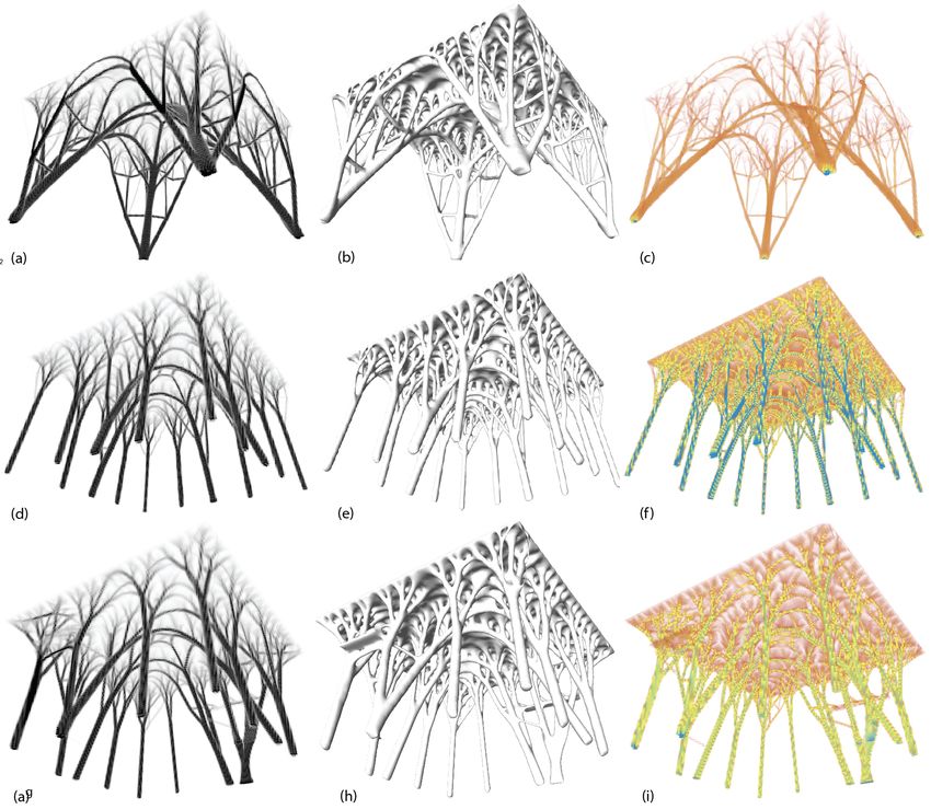
146 | eCAADe 36 - APPLICATIONS IN CONSTRUCTION & OPTIMISATION - Volume 1Figure 7
Result forms from
series I. From left:
Densities as points,
compliance as
points, forma as
volume. Test 3A fig.
a-c, test 3B fig. d-f
and test 3C fig. g-i .
3A as door and window openings caused deforma- in relation to the form obtained in the 3A study, we
tion symmetrical structure obtained in the previous can not forget that the form received is a response to
study. The structure has been enriched with two a specific problem. Thus it was obtained adapted to
additional pillars that have taken over some of the the selected request structure which is unique. This
loads from areas where the V-shaped slanted column allows the designer to look for the best design solu-
could not be created (Figure 7d). The form obtained tions at the same time examining their impact on the
through the holes has become chaotic (Figure 7e- derived form and structure.
f ). Purity form achieved in the previous study has Test 3C. Initial conditions are presented on figure 6c.
been disturbed by additional structures, making dis- Changing the location of the window opening is not
sonance. However, despite the less clear appearance
APPLICATIONS IN CONSTRUCTION & OPTIMISATION - Volume 1 - eCAADe 36 | 147drastically affected the entire structure in compari- Computation Specialty Conference, pp. 445-454
son with the results of 3A. When analysing Figure 7g Kutylowski, R 2004, Optymalizacja topologii kontin-
and Figure 7h, the differences in form, except the col- uum materialnego, Oficyna Wydawnicza Politechniki
Wrocławskiej, Wrocław
umn relocation due to the appearance of the win-
Liu, K and Tovar, A 2014, ’An efficient 3D topology opti-
dow, are not so visible. Also minor changes have oc- mization code written in Matlab’, Structural and Mul-
curred in the compliance distribution shown in Fig- tidisciplinary Optimization, 50(6), pp. 1175-1196
ure 7i. However, this does not change the fact that Lorensen, WE and Cline, HE 1987, ’Marching cubes: A
the obtained system is characterised by an equally high resolution 3D surface construction algorithm’,
complicated structure as the form obtained in the 3B ACM SIGGRAPH Computer Graphics, 21(4), pp. 163-
169
study.
Martinez-Frutos, J and Herrero-P\, D 2015, ’Efficient
matrix-free GPU implementation of Fixed Grid Finite
CONCLUSION Element Analysis’, Finite Elements in Analysis and De-
The results from all series of tests clearly show that sign, 104, pp. 61-71
Ohmori, H 2010, ’Computational Morphogenesis: Its
the obtained structures can successfully fulfil the role
Current State and Possibility for the Future’, Interna-
of architectural form or be an inspiration for it. Cre- tional Journal of Space Structures, 25(2), pp. 75-82
ated software gives unlimited possibilities in the pro- Sanders, J, Kandrot, E and Piwko, Ł 2012, Cuda
cess of creation of forms. Each new boundary con- w przykładach: Wprowadzenie do ogólnego pro-
ditions, the shape of the design space, whether the gramowania procesorów, Helion, Gliwice
restrictions, will result in generating a new form, Schmidt, S and Schulz, V 2011, ’A 2589 line topology op-
timization code written for the graphics card’, Com-
adapted to the requirements set by the user. The
puting and Visualization in Science, 14(6), pp. 249-
implementation of the form-forming principles of 256
topological optimisation using the idea of paramet-
ric design enables designers and architects to look
for structures and inspirations for architectural forms
in a simplified and intuitive way. The use of numer-
ical methods as a base for generating forms has re-
sulted in receiving interesting structures rich in inter-
esting detail, which have gained additional value. Fi-
nal forms are not composed from ready-made archi-
tectural solutions, but it is a unique answer to a given
problem.
REFERENCES
Bendsoe, MP and Sigmund, O 2004, Topology Optimiza-
tion: Theory, Methods, and Applications, Springer
Berlin Heidelberg, Berlin, Heidelberg
Białkowski, S 2017 ’tOpos - GPGPU Accelerated Struc-
tural Optimisation Utility for Architects’, eCAADe
2017, Rome, pp. 679-688
Block, P, Knippers, J, Mitra, NJ and Wang, W (eds) 2015,
Advances in Architectural Geometry 2014, Springer In-
ternational Publishing, Cham
Guest, JK and Moen, CD 2010 ’Reinforced Concrete De-
sign with Topology Optimization’, 19th Analysis and
148 | eCAADe 36 - APPLICATIONS IN CONSTRUCTION & OPTIMISATION - Volume 1You can also read