TTEECCHHNNIICCAALL DDEESSCCRRIIPPTTIIOONN - MD Helicopters
←
→
Page content transcription
If your browser does not render page correctly, please read the page content below
TECHNICAL DESCRIPTION

                          MD 902
                          EXPLORER

MD Helicopters, Inc.
Sales and Marketing
4555 E. McDowell Rd.
Mesa, AZ 85215
PH: 480.346.6474
FAX: 480.346.6339
www.mdhelicopters.com
sales@mdhelicopters.com

    MISSION PROVEN, CHALLENGE READY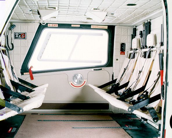
THIS PAGE INTENTIONALLY LEFT BLANK
TECHNICAL DESCRIPTION

                        MD 902 EXPLORER

                                  MD Helicopters, Inc.
                                 4555 E. McDowell Rd
                                    Mesa, Arizona
                                    CAGE: 1KVX4
                                  DUNS: 054313767
                                www.mdhelicopters.com

This Technical Description includes information and intellectual property that is the
property of MD Helicopters, Inc. (MDHI). It provides general information for
evaluation of the design, equipment, and performance of the MD 902 helicopter. The
information presented in this Technical Description does not constitute an offer and is
subject to change without notice. This proprietary information, in its entirety, shall not
be duplicated, used, or disclosed—directly or indirectly, in whole or in part—for any
purpose other than for evaluation. MD Helicopters, Inc. reserves the right to revise this
Technical Description at any time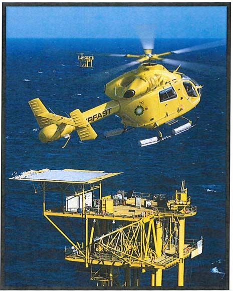
MD 902 Explorer
                                                                  Technical Description

REPORT NO.:   MD14021407-902TD
NO. OF PAGES: 74

Use or disclosure of data in this Technical Description is subject to the restriction on
the cover page of this document.

ATTACHMENTS: None

Revision By         Approved         Date      Pages and/or Paragraphs Affected
New      RCP                         14-Feb-14 All (Initial Issue)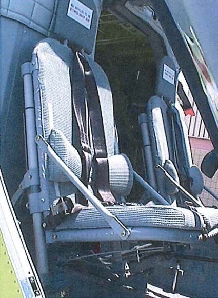
MD 902 Explorer
                                                                                                            Technical Description

                                                            Contents

1.      FOREWORD ........................................................................................................ 1
2.      KEY ADVANTAGES / FEATURES ...................................................................... 3
3.      CERTIFICATION .................................................................................................. 9
        3.1    CATEGORY A OPERATION........................................................................................... 9
        3.2    CERTIFICATES .......................................................................................................... 10
        3.3    DESIGNATION ........................................................................................................... 10
        3.4    OPERATORS ............................................................................................................ 10
4.      DIMENSIONS, WEIGHT, AND CONFIGURATION ............................................ 11
        4.1    EXTERNAL DIMENSIONS............................................................................................ 11
        4.2    INTERIOR DIMENSIONS ............................................................................................. 11
        4.3    WEIGHT ................................................................................................................... 13
        4.4    CONFIGURATIONS .................................................................................................... 13
5.      MD 902 TWIN-ENGINE HELICOPTER .............................................................. 15
        5.1    SYSTEM DESCRIPTION ............................................................................................. 15
        5.2    STANDARD VISUAL FLIGHT RULE EQUIPMENT CONFIGURATION.................................. 17
        5.3    INSTRUMENT FLIGHT RULE REQUIRED EQUIPMENT.................................................... 19
        5.4    OPTIONAL EQUIPMENT CONFIGURATION ................................................................... 20
        5.5    MAIN FUSELAGE ASSEMBLY ..................................................................................... 22
        5.6    EXTERIOR ................................................................................................................ 23
        5.7    EXTERNAL LIGHTING ................................................................................................ 23
        5.8    INTERIOR ................................................................................................................. 24
               5.8.1      Cockpit .................................................................................................................... 24
               5.8.2      Cabin Compartment ................................................................................................ 25
               5.8.3      Baggage Compartment ........................................................................................... 27
        5.9    SYSTEMS ................................................................................................................. 28
               5.9.1      Fuel System ............................................................................................................ 28
               5.9.2      Turboshaft Engine ................................................................................................... 29
               5.9.3      Drive System ........................................................................................................... 31
               5.9.4      Main Rotor ............................................................................................................... 33
               5.9.5      Flight Control System .............................................................................................. 35
               5.9.6      Hydraulic System .................................................................................................... 36
               5.9.7      Fire Detection/Suppression System ........................................................................ 37
Report No. MD14021407-902TD                                            i                                                        14 February 2014
     USE OR DISCLOSURE OF DATA IN THIS TECHNICAL DESCRIPTION IS SUBJECT TO THE RESTRICTION ON THE COVER PAGE

                                                       MDHI PROPRIETARY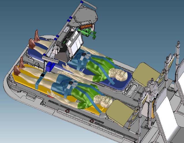
MD 902 Explorer
Technical Description
5.9.8 Electrical System ..................................................................................................... 39
5.9.9 Environmental Control System................................................................................ 41
5.9.10 Integrated Instrumentation Display System ............................................................ 41
5.9.11 Next-Generation Digital Electronic Flight Instrument System ................................. 44
6. PERFORMANCE SPECIFICATIONS ................................................................ 47
6.1 ENVIRONMENTAL IMPACT.......................................................................................... 48
6.2 SAFETY.................................................................................................................... 51
6.2.1 Crashworthiness...................................................................................................... 53
6.3 HUMAN SYSTEMS INTERFACE ................................................................................... 53
7. MAINTENANCE AND SERVICING .................................................................... 57
7.1 MAINTENANCE ......................................................................................................... 57
7.2 SERVICING ............................................................................................................... 60
7.3 HOURLY COST ......................................................................................................... 64
8. PRODUCT SUPPORT ....................................................................................... 65
8.1 TRAINING ................................................................................................................. 65
8.1.1 Pilot Training ........................................................................................................... 65
8.1.2 Transition Flight Training ......................................................................................... 65
8.1.3 Recurrent Flight Training ......................................................................................... 65
8.1.4 Maintenance Training .............................................................................................. 66
8.2 WARRANTY .............................................................................................................. 66
8.2.1 Warranty Claims ...................................................................................................... 66
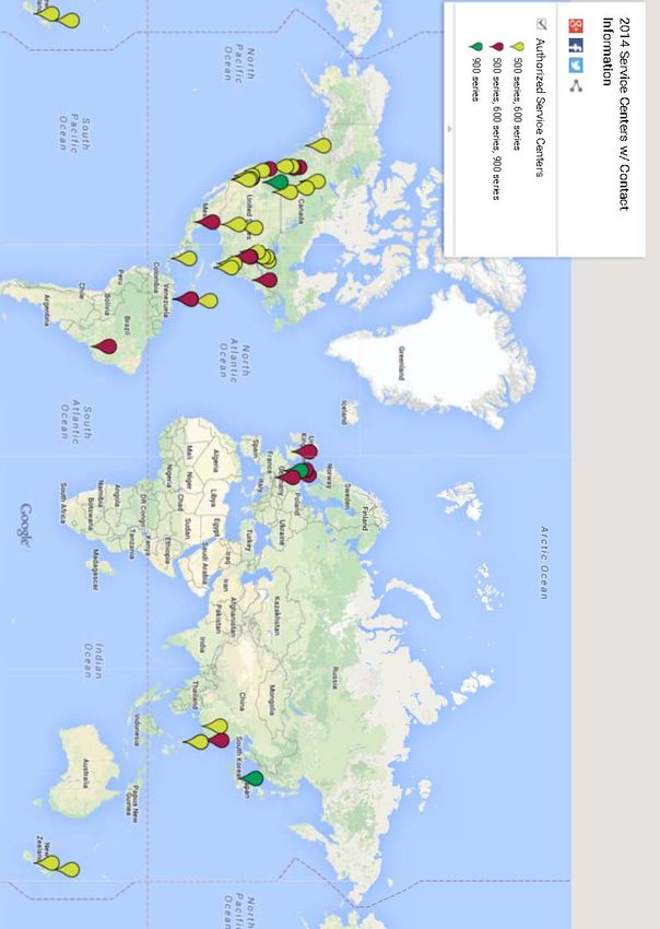
8.3 SERVICE CENTERS ................................................................................................... 67
8.4 FIELD SERVICE......................................................................................................... 67
Report No. MD14021407-902TD ii 14 February 2014
USE OR DISCLOSURE OF DATA IN THIS TECHNICAL DESCRIPTION IS SUBJECT TO THE RESTRICTION ON THE COVER PAGE
MDHI PROPRIETARY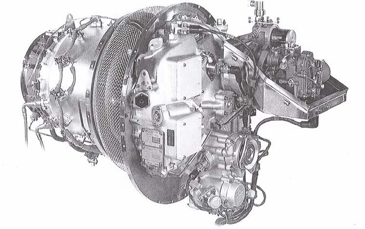
MD 902 Explorer
                                                                                Technical Description

1. FOREWORD
This document presents basic technical description of the eight-place MD 902 Explorer
helicopter built in Mesa, Arizona, USA. It is designed to provide high-level technical
information of the helicopter, advantages/features, and configurations. For more detailed
information an MD 902 Product Specification is available by contacting one of the Sales Team
Members listed below.

Ideally suited for multi-mission capabilities ranging from VVIP/passenger transport, emergency
medical services, to utility missions, the MD 902 has a large cabin with sliding cabin doors on
each side, integrated safety features, reduced noise signature, and no tail rotor (NOTAR®). The
MD 902 is certified for single-pilot operation under visual flight rules/visual meteorological
conditions, and capable of operation under instrument flight rules. Powered by two dual-
redundant Pratt and Whitney-Canada Model 207E turboshaft engines, the MD 902 features a
bearing-less, composite, fully-articulated main rotor system, and NOTAR® anti-torque system.
The NOTAR® system significantly improves safety and provides a major reduction in noise
profile. The MD 902 is Federal Aviation Administration (FAA)/Joint Aviation Administration
(JAA) certified with full Category A design standards to JAR-OPS 3 performance Class I, and is
approved for use in over 50 worldwide countries.

MD Helicopter, Inc. Sales and Business Development

   SALES                                                   BUSINESS DEVELOPMENT
   Phone: 480.346.6474                                        Marc Brodeur
   FAX: 480.346.6339                                          Vice President, Military & Commercial Sales
   E-Mail: sales@mdhelicopters.com                            Phone: (480) 346.6532
                                                              Cell: (480) 622.3118
                                                              E-Mail: marc.brodeur@mdhelicopters.com

Report No. MD14021407-902TD                           1                                        14 February 2014
    USE OR DISCLOSURE OF DATA IN THIS TECHNICAL DESCRIPTION IS SUBJECT TO THE RESTRICTION ON THE COVER PAGE

                                           MDHI PROPRIETARY
MD 902 Explorer
                                                                                Technical Description

                          THIS PAGE INTENTIONALLY LEFT BLANK

Report No. MD14021407-902TD                           2                                        14 February 2014
    USE OR DISCLOSURE OF DATA IN THIS TECHNICAL DESCRIPTION IS SUBJECT TO THE RESTRICTION ON THE COVER PAGE

                                           MDHI PROPRIETARY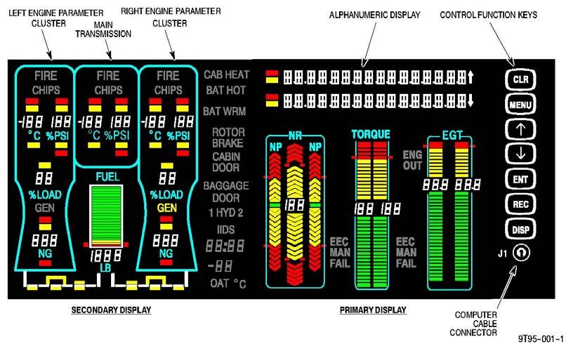
MD 902 Explorer
Technical Description
2. KEY ADVANTAGES / FEATURES
Using inputs from an international turbine-engine helicopter owners and operators advisory
group, MD Helicopters designed and developed the MD 902 Explorer (see Fold-Out page) to be
a new performance standard for a multi-purpose twin-engine helicopter. The MD 902 is a twin
turbine engine, rotary-wing aircraft. It has a cruising speed of 131 knots (246 kph / 152 mph),
with a useful internal load at 6,500 pound maximum gross weight is 3,125 pounds (1,417 kg).
Hover out of ground effect is 8,780 feet (2,676 m) and hover in ground effect is 10,650 feet
(3,246 m). The rate of climb at maximum gross weight is 2,120 feet/min (10.7 m/sec). The
maximum operating altitude is 14,000 feet (4,267 m) with a -40 to +52C (-40 to 126F) operating
temperature range.
THE MD 902 EXPLORER ADVANTAGES / FEATURES
Airframe
Simple system design Composite fuselage and tail boom
Mature, field-proven systems and provides strength, light weight,
components corrosion control, and includes high-
Large cabin/cabin entrance intensity radiated frequency/lightning-
o 41 cubic feet (3.8 cubic meters) strike protection capability
useable floor space Separate baggage compartment
o 173 cubic feet (4.9 cubic meters) o 52 cubic feet (1.47 cubic meters)
total cabin volume total baggage compartment
o 52 inch (1.32 meter) cabin entrance volume
opening Flexible cabin seating/layout options
Innovative, fully-articulated, hinge-less, Quick attach/detach capable cabin utility
composite, main rotor blades provide seats
improved flight control/dynamics and Twin, full-authority digital-electronic-
unparalleled low-vibration levels controlled (FADEC) turboshaft engines
Speed, agility, and load-capable External power receptacle
Single-pilot instrument flight rule rated Energy-attenuating landing gear
Certified to 14 CFR Part 27; VFR Integrated landing gear dampers
Certified to 14 CFR Part 27; Criteria for Main rotor system removal independent
Category A from main rotor transmission
Certified to JAR Part 27; JAR-OPS 3 Main rotor transmission removal
performance; Class 1 aircraft independent from main rotor system
Certified to 14 CFR Part 21; High- Proven record of high dependability
intensity radiated fields protection High availability
Approved/certified in over 50 countries
worldwide
Report No. MD14021407-902TD 3 14 February 2014
USE OR DISCLOSURE OF DATA IN THIS TECHNICAL DESCRIPTION IS SUBJECT TO THE RESTRICTION ON THE COVER PAGE
MDHI PROPRIETARY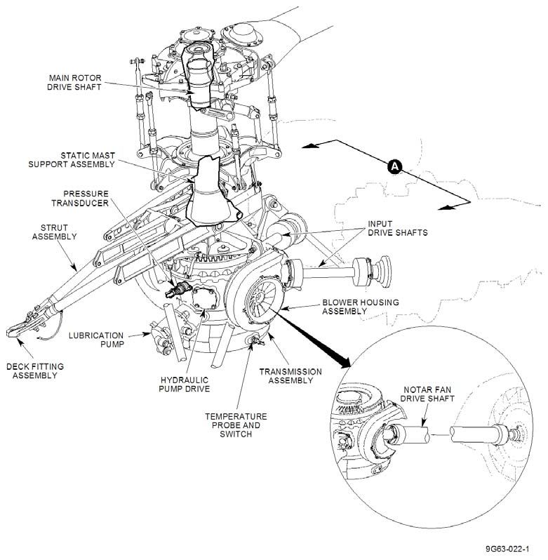
MD 902 Explorer
Technical Description
THE MD 902 EXPLORER ADVANTAGES / FEATURES
Integrated Safety Features
No tail rotor (NOTAR®) anti-torque Turboshaft engine fuel metering unit
system eliminates the spinning tail rotor, enclosure for fuel-containment
tail rotor gearbox, and tail rotor drive shaft Turboshaft engine fuel drain to prevent
Designed for operator ease combustor fuel accumulation
High-strength composite airframe with A- Integral powerplant, fuel, hydraulic and
frame structure designed to absorb energy electric system monitoring and display
in an emergency landing by yielding through the integrated electronic flight
progressively instrument system
Crew and passenger seats are energy- Engine/main rotor transmission fire
attenuating and meet Federal Aviation detection/suppression system
Regulation (FAR)/Joint Aviation Main rotor transmission and NOTAR®
Regulation (JAR) 27.562 emergency fan drive shafts incorporate anti-flail
landing dynamic requirements; 30g devices if a flexible joint failure were to
vertical and 18.4 g forward deceleration occur
protection Hydraulic system pumps incorporate
No use of magnesium integral spline shear couplings designed
Component assembly designed to prevent to fail before the splined drive shafts
galvanic corrosion Hydraulic system filter automatic bypass
Cabin doors slide out of the way to if filter becomes restricted
eliminate personnel obstruction hazard Fuel filter automatic bypass if filter
Cabin sliding doors incorporate becomes restricted
emergency quick-egress windows Hydraulic system pressure and
Main rotor static mast/base designed to be temperature indication
fail-safe to 100-percent design load Crew-seat five-point restraints
Dual-redundant hydraulic system Passenger seats provided with three- or
Single, crash-resistant elastomeric fuel four-point restraints
cell mounted between crash-resistant keel Caution/warning annunciators/audible
beams and bulkheads below the cabin warning tones
floor Wire harnesses are electro-magnetic
Fuel lines incorporate self-sealing interference shielded
frangible valves to prevent leaking in Power generating system electrical
hard-landing/crash events system and wiring are separated to
Fuel cell vent system rollover valves prevent essential bus power interruption
automatically close when aircraft exceeds due to any single-point failure
a 45-degree pitch or roll angle Essential electrical bus designed to
Tail boom end-mounted tail skid prevent any single-point failure
Dual redundant turboshaft engines allow External ground-plug connection
for one engine inoperative operation
Report No. MD14021407-902TD 4 14 February 2014
USE OR DISCLOSURE OF DATA IN THIS TECHNICAL DESCRIPTION IS SUBJECT TO THE RESTRICTION ON THE COVER PAGE
MDHI PROPRIETARYMD 902 Explorer
Technical Description
THE MD 902 EXPLORER ADVANTAGES / FEATURES
Supportability Features
Designed for ease of maintenance and Built-in Maintenance aids (Contd.):
supportability o Turboshaft engine hinged/captive
Modular system design composite access panels
o Engine fuel and oil filter
Designed for reparability
impending bypass indicators
Low direct operating costs
o Engine oil chip detector
Maximum use of line replaceable units: o Main rotor transmission chip
o Engines detector/burner
o Avionics/communication o Integrated engine compressor
o Flight controls wash system
o Main rotor blades o Engine oil filler cap/dipstick
o Main rotor drive shaft o Main rotor transmission filler cap
o Main rotor transmission o Engine, main rotor transmission,
o Main rotor transmission drive shaft and hydraulic system oil level
o NOTAR® fan sight gage
o Main rotor mast o Hydraulic system manual fill
o Landing gear system
o Canopies o Integrated hydraulic system
o Doors pressure fill system
o Door handles o Hydraulic system sampling valve
o Door windows o Hydraulic system external bleed
o Seats valve
o Seat restraints o Hydraulic system pressure fill
o Tail boom isolation valve
o Oil-cooler/blowers o Built-in aircraft systems condition
o Empennage monitoring, exceedance, and
o Tail boom skid engine trend analysis capability,
Built-in maintenance aids downloadable by maintenance
o Turboshaft engine composite personnel
access panels are hinged and o Main rotor and NOTAR® fan
captive balance monitoring system
o Footsteps and hand-holds located o Landing gear ground handling
on each side for upper deck access wheel quick attach feature
without ground support equipment
Human Systems Integration Features
Unobstructed forward +160-degree Flight controls designed for maximum
vertical and 230-degree horizontal cockpit movement with minimal crew input
field of view Cabin access/observation from cockpit
Adjustable anti-torque pedals to Integrated cockpit and cabin entry steps
accommodate different sized Integrated visual/audible warning
Report No. MD14021407-902TD 5 14 February 2014
USE OR DISCLOSURE OF DATA IN THIS TECHNICAL DESCRIPTION IS SUBJECT TO THE RESTRICTION ON THE COVER PAGE
MDHI PROPRIETARYMD 902 Explorer
Technical Description
THE MD 902 EXPLORER ADVANTAGES / FEATURES
crewmembers indication for flight critical functions
Cockpit designed to accommodate 25th to Main rotor transmission acoustically
95th percentile male/female flight crew isolated for cockpit/cabin noise
Ergonomic designed cyclic and collective reduction
controls Cabin sound proofing
Hydraulic-boosted flight controls
Engine
Dual redundant turboshaft engines allow Turboshaft engine fuel metering unit
for one engine inoperative operation enclosure for fuel-/vapor-containment
Engine hydro-mechanical backup in the Turboshaft engine fuel drain to prevent
event of FADEC failure combustor fuel accumulation
Externally accessible water wash system
Monitoring Instrumentation
Integrated instrument display system Digital avionics suite in work
Environmental Impact
Certified to Part 36, Appendix H; Noise Closed-circuit fuel recirculation system
Lowest noise profile of light twin-engine to avoid fuel/vapor release
class helicopters
Report No. MD14021407-902TD 6 14 February 2014
USE OR DISCLOSURE OF DATA IN THIS TECHNICAL DESCRIPTION IS SUBJECT TO THE RESTRICTION ON THE COVER PAGE
MDHI PROPRIETARYMD 902 Explorer
Technical Description
64
66 65
66
63
90 94
66
25
101
LEGEND
1. Battery access door 34.Hydraulic reservoir 67. Not shown 100. Horizontal stabilizer mount
2. Battery 35.Hydraulic pressure fill connectors 68.Bearing-less rotor hub 101. Tail skid
112 3. Windshield defog air duct 36. Maintenance hand hold 69. Oil cooler exhaust 102. Low-pressure tail boom plenum
4. Windshield canopy 37. Cabin door 70. Blower 103. Coanda slots (2)
5. Magnetic compass 38. Utility seat 71. Oil cooler 104. Rotor down wash (not shown)
6. Glareshield 39. Maintenance steps 72. Oil cooler intake 105. Low pressure air split
7. Instrument panel 40. Fuel fill (on opposite side) 73. Engine mounts 106. Coanda lift force (not shown)
8. Torque (yaw) control pedals 41. Composite fuselage 74. NOTAR fan driveshaft 107. P&WC 207E turboshaft engine
9. Avionics access 42. Lower cabin door rail 75. Stators 108. Not shown
10. Copilot entry step 43. Fuselage stringers 76. Engine gearbox 109. Engine air intake
11. Landing gear mount 44. Fuel tank 77. NOTAR fan intake 110. Engine accessory gearbox
12. Collective control 45. Cabin door latch 78. NOTAR variable pitch fan 111. Power output shaft
13. Copilot door 46. Composite floor panels 79. Stators 112. Baggage compartment door
14. Energy-attenuating seat 47. Utility seat 80. Not shown 113. Fuselage strake
15. Copilot seat 48. Seat mount 81. Tail boom mount 114. Baggage compartment
16. Five-point restraint 49. Cabin door 82. Aft top fairing 115. Cabin lining and sound proofing
17. Cyclic control 50. Upper cabin door rail 83. Engine exhaust 116. Fuselage A-frame
18. Center console 51. Drivetrain mounting deck 84. Engine exhaust 117. Baggage compartment floor
19. Circuit breaker panel 52 Drive system supports 85. Composite tail boom 118. Maintenance step
20. Pilot seat 53. Hydraulic pump 86. Vertical stabilizer 119. Condenser air outlet
21. Headset stowage 54.Oil pump 87. Vertical stabilizer hinge post 120. Maintenance step
22. Cockpit air duct 55. Main transmission 88. Composite skin panels 121. Fuel feed pipe
23. Control rod linkages 56. Anti-vibration mount 89. Vertical stabilizer trim actuator 122. Landing gear mount
24. Instrument light 57. Main transmission upper support 90. VHF antenna 123. Landing gear damper
25. Main rotor blade abrasion strip 58. Swash plate 91. Horizontal stabilizer 124. Passenger step
26. Composite blade spar 59. Rotor mast 92. Anti-collision light 125. Landing gear skid
27. Foam-filled trailing edge 60. Blade pitch control rods 93. NOTAR tail thruster
28. Composite skin panel 61. Composite flexbeams 94. Rotating thruster fairing
29. Composite fairing 62. Blade root attachment joint 95. Louvered tail thruster
30. Composite rotor head fairing (not shown) 63. Composite pitch case 96. Not shown
31. Air conditioning equipment 64. Blade tip balance pocket 97. Vertical stabilizer
32. Water separator 65. Trim tab 98. Navigation light
33. Hydraulic actuators 66. Five blade rotor 99. Anti-collision light
MD 902 Explorer.
Report No. MD14021407-902TD 7 14 February 2014
USE OR DISCLOSURE OF DATA IN THIS TECHNICAL DESCRIPTION IS SUBJECT TO THE RESTRICTION ON THE COVER PAGE
MDHI PROPRIETARYMD 902 Explorer
Technical Description
THIS PAGE INTENTIONALLY LEFT BLANK
Report No. MD14021407-902TD 8 14 February 2014
USE OR DISCLOSURE OF DATA IN THIS TECHNICAL DESCRIPTION IS SUBJECT TO THE RESTRICTION ON THE COVER PAGE
MDHI PROPRIETARYMD 902 Explorer
Technical Description
3. CERTIFICATION
The MDHI MD 902 is a commercial aircraft FAA type-certified under Code of Federal
Regulations (CFR) Title 14, Part 27, visual flight rules (VFR) day and night occurred in
December 1994. Joint Aviation Authorities (JAA) validation, which led directly to Joint Aviation
Regulation (JAR) Part 27 Type Certification in all 27 member countries, was awarded in July
1996. Category A certification, which incorporates 45 additional Part 29 design and performance
regulations, supports deliveries of a JAR-OPS 3 performance Class 1 aircraft.
The MD 902 is certified to 14 CFR Part 27 through amendment 27-26 dated April 5, 1990, and
special condition for high intensity radiated fields (HIRF) protection per 14 CFR 21.16; Part 36
Appendix H, Noise, effective on the date of Type Certificate, and Part 27, Amendment 27-33,
Appendix C - "Criteria for Category A" (November 1997).
The MD 902 is approved for use in over 50 countries worldwide.
3.1 Category A Operation
The MD 902 is certified for CFR Part 27,
Appendix C, Category A operations from clear
airfields, heliports, and elevated helipads when
the appropriate instruments and equipment are
installed and operable The MD 902
demonstrated safe single-engine flight profiles to
the FAA that met or exceeded aircraft strength
requirements and safety design and construction
criteria. The MD 902 was certified for Category
A Rotorcraft Operations on August 8, 1996. The
Category A MD 902 demonstrated engine
takeoff performance that met the following:
If one engine fails after the start of
takeoff prior to the takeoff decision
point, the MD 902 can return to the point
of takeoff and stop safely (rejected
takeoff)
If one engine fails during takeoff and
climb out after the takeoff decision point, the MD 902 can safely continue the takeoff and
climb out
If the takeoff and climb out is continued, a configuration and airspeed can be achieved
that will allow for the safe return and landing at an elevated pad, a ship landing deck, or a
clear landing area
Report No. MD14021407-902TD 9 14 February 2014
USE OR DISCLOSURE OF DATA IN THIS TECHNICAL DESCRIPTION IS SUBJECT TO THE RESTRICTION ON THE COVER PAGE
MDHI PROPRIETARYMD 902 Explorer
Technical Description
If one engine fails during landing approach prior to the landing decision point, the MD
902 can climb out and achieve an airspeed that allows continued flight (balked landing)
If one engine fails during landing after the landing decision point, the MD 902 can land
and stop safely.
Maximum altitude for MD 902 Category A operations is 10,000 feet density altitude. Category A
operation at clear airfields, heliports, and elevated helipads are limited with winds from the side
and aft of the aircraft (60 degrees from rotor center, forward). Heliport and elevated helipad
operation is limited to operation with solid surfaces, minimum dimensions of 50 feet by 50 feet.
3.2 Certificates
Production, type, and supplemental type certificates are maintained by MDHI.
A standard airworthiness certificate (FAA form 8100-2), displayed in the aircraft is the FAA
official authorization allowing for the operation of type-certificated aircraft. The airworthiness
certificate is displayed in the aircraft and remains valid as long as the aircraft meets the approved
type design, is in a condition for safe operation, and maintenance, preventive maintenance, and
alterations are performed in accordance with Code of Federal Regulations Title 14, Part 21.
3.3 Designation
The FAA model designation is MD 900, and the International Civil Aviation Organization
(ICAO) Type Designation is EXPL (former ICAO Type Designation number was HU90). The
MDHI commercial designation is MD 902.
3.4 Operators
Over 130 MD 900-series helicopters are operating worldwide with combined operational hours
of greater than 400,000 hours. More than fifty percent of the fleet is used in the Police /
emergency medical services
(EMS) role; other fleet operators
perform search and rescue (SAR),
very important person (VIP),
utility, and military activities
(including armed variants). The
MD 900-series helicopter
provides superior performance,
best payload, and lowest operating
costs of any light twin-engine
helicopter.
Report No. MD14021407-902TD 10 14 February 2014
USE OR DISCLOSURE OF DATA IN THIS TECHNICAL DESCRIPTION IS SUBJECT TO THE RESTRICTION ON THE COVER PAGE
MDHI PROPRIETARYMD 902 Explorer
Technical Description
4. DIMENSIONS, WEIGHT, AND CONFIGURATION
4.1 External Dimensions
The MD 902 external dimensions are provided in the following table and shown in the figure
below.
MD 902 Explorer External Dimensions
Dimension,
Parameter
ft (m)
Fuselage Width (aft top) 5.91 (1.80)
Fuselage Length 18.25 (5.56)
Horizontal Stabilizer Width 9.33 (2.84)
Landing Skid Width 7.33 (2.23)
Ground to Rotor Height 10.92 (3.33)
Ground to Fuselage Bottom Height 1.25 (0.38)
Main Rotor Diameter 33.83 (10.31)
4.2 Interior Dimensions
The MD 902 interior dimensions are provided in the following table and shown in the second
figure below.
MD 902 Explorer Internal Dimensions
Dimension,
Parameter
ft (m)
Crew Compartment Width 4.30 (1.45)
Crew Compartment Length 3.60 (1.10)
Passenger Compartment Width 4.30 (1.45)
Passenger Compartment Length 6.30 (1.90)
Passenger Door Height (not shown) 4.08 (1.24)
Passenger Door Width (not shown) 4.16 (1.27)
Report No. MD14021407-902TD 11 14 February 2014
USE OR DISCLOSURE OF DATA IN THIS TECHNICAL DESCRIPTION IS SUBJECT TO THE RESTRICTION ON THE COVER PAGE
MDHI PROPRIETARYMD 902 Explorer
Technical Description
MD 902 Explorer External Dimensions
Report No. MD14021407-902TD 12 14 February 2014
USE OR DISCLOSURE OF DATA IN THIS TECHNICAL DESCRIPTION IS SUBJECT TO THE RESTRICTION ON THE COVER PAGE
MDHI PROPRIETARYMD 902 Explorer
Technical Description
MD 902 Interior Dimensions
4.3 Weight
The MD 902 nominal empty weight is 3,375 pounds (1531 kg).
Operational weight limit range of the MD 902 is 3,500 pounds (1,588 kg) minimum to 6,500
pounds (2,948 kg). An option is available to increase the operational weight limit to 6,770
pounds (3,071 kg).
4.4 Configurations
The MD 902 can be configured for a variety of different configurations. Configuration examples
are shown in the following views:
Report No. MD14021407-902TD 13 14 February 2014
USE OR DISCLOSURE OF DATA IN THIS TECHNICAL DESCRIPTION IS SUBJECT TO THE RESTRICTION ON THE COVER PAGE
MDHI PROPRIETARYMD 902 Explorer
Technical Description
Optional Cabin Configurations are Available Including EMS, Search and Rescue,
Utility, and VIP Passenger Transport
Report No. MD14021407-902TD 14 14 February 2014
USE OR DISCLOSURE OF DATA IN THIS TECHNICAL DESCRIPTION IS SUBJECT TO THE RESTRICTION ON THE COVER PAGE
MDHI PROPRIETARYMD 902 Explorer
Technical Description
5. MD 902 Twin-Engine Helicopter
The MD 902 is a twin-engine rotary-wing aircraft certified for single-pilot operation under visual
flight rules/visual meteorological conditions, and capable of operation under instrument flight
rules. The MD 902 is fully certified for Category A operations from clear airfields, heliports, and
elevated helipads
5.1 System Description
The MD 902 is an eight-place, twin-engine, multipurpose helicopter constructed of an aluminum
frame with a composite outer structure. It has a bearing-less, composite, fully-articulated rotor
system, with the patented NOTAR® anti-torque system. The engines have a direct input to the
transmission, with no combining gearbox. A single, short shaft from the transmission drives the
NOTAR® fan, and two shafts drive the engine and transmission oil cooling system.
The main rotor is supported by a hollow static mast mounted to the primary structure that
absorbs all of the flight loads, allowing the transmission to provide only torque. The transmission
is separated from the static mast by an acoustic isolator, thus reducing noise into the cabin and
cockpit areas.
There are only three wetted areas, which are checked daily through view ports. The hydraulic
system is a dual-redundant system for reliability. The outer skin of the aircraft is composite, with
no magnesium, providing strength, light weight, and all-weather capability. The outer skin also
incorporates high-intensity radiated frequency/lightning-strike protection capabilities. The fuel
cells are separated away from the outer skin, enclosed by two deep keel beams, and all of the fuel
lines incorporate frangible fittings.
The main display for aircraft systems performance and monitoring is the integrated instrument
display system (IIDS), a digital and analog information processing, storage, and display system
on the MD 902 helicopter. The IIDS receives input signals from various aircraft system
components for status display, limit checking and display (warning/caution indication), operation
information, trend data, rotor and NOTAR® fan balance monitoring, and data logging.
All of the crew and passenger seats are energy attenuating, and meet the new Federal Aviation
Regulation (FAR)/JAR 27.562 emergency landing dynamic requirements. The landing gear is a
non-retractable skid. Large, 52 inch (1.32 m) sliding doors are on each side of the spacious cabin.
The crew doors are hinged and a hinged door at the aft end of the fuselage allows for baggage or
alternate loading.
A diagram of the major system components of the MD 902. System/component details are
shown below.
Report No. MD14021407-902TD 15 14 February 2014
USE OR DISCLOSURE OF DATA IN THIS TECHNICAL DESCRIPTION IS SUBJECT TO THE RESTRICTION ON THE COVER PAGE
MDHI PROPRIETARYMD 902 Explorer
Technical Description
MD 902 Explorer System/Component Details
Report No. MD14021407-902TD 16 14 February 2014
USE OR DISCLOSURE OF DATA IN THIS TECHNICAL DESCRIPTION IS SUBJECT TO THE RESTRICTION ON THE COVER PAGE
MDHI PROPRIETARYMD 902 Explorer
Technical Description
5.2 Standard Visual Flight Rule Equipment Configuration
The MD 902 is configured with standard VFR equipment that is included with the basic aircraft
procurement.
MD 902 Standard VFR Equipment
Airframe
Left-/right-hand sliding cabin doors Hydraulic system single-point pressure
Baggage compartment door fill ports
Sliding cabin and cockpit door windows Fuselage tub inspection panels
Keyed door and access panel locks External power receptacle
Left and right side passenger steps Twenty-two amp, 24 Vdc NICAD
Anti-collision lights (2) battery
Position lights and strobe lights Main rotor and NOTAR® fan balance
Hover and approach lights monitoring system
Single-point gravity refueling port Vertical stabilizer control system
159-gallon (602 liter) fuel system Air conditioning
Jack pad installation kit One color standard paint
Dual hydraulic-system manual-fill hand Left-/right-passenger steps
pump Vertical stabilizer control system
Heater/defogger Ram air ventilation w/blower
Rain gutter set
Carbide skid shoes
Interior - Cockpit
Energy-attenuating crew seats with five- Rotorcraft Flight Manual storage and
point restraint harness Certificate of Airworthiness display
Gray cockpit trim/carpeting envelope
Twenty-eight volt utility outlets Dual-redundant hydraulic-boosted
Cockpit pneumatic door openers flight control system
Copilot floor-mounted intercom switch Dual right-hand command flight
Cockpit fire extinguisher controls
Crew wander utility and dome light Right-hand command rotor brake
David Clark headsets (2) Single-pilot inverted-L instrument
panel
Interior – Cabin
Cabin soundproofing Medical first-aid kit
Beige cabin utility trim (wall, ceiling, One cabin station intercom jack
carpet) Two cabin threshold lights
Twenty-eight volt utility outlets Cabin temperature control
Flush-mounted cargo tie downs
Report No. MD14021407-902TD 17 14 February 2014
USE OR DISCLOSURE OF DATA IN THIS TECHNICAL DESCRIPTION IS SUBJECT TO THE RESTRICTION ON THE COVER PAGE
MDHI PROPRIETARYMD 902 Explorer
Technical Description
MD 902 Standard VFR Equipment
Baggage Compartment
Baggage area utility light Baggage door fixed window
Engine
Twin FADEC Pratt & Whitney-Canada Integrated water wash system
Model 207E Engines, 710 shaft Engine fire detection/suppression
horsepower (shp) (530 kiloWatt [kW]) system
turboshaft engines Engine inlet screens
Monitoring Instrumentation
AMS-43 three panel intercom system Outside air temperature indicator
audio control Magnetic compass
Airspeed indicator Single pitot tube (VFR only)
Avionics master switch Analog cockpit (to be replaced by a
digital cockpit: Refer to Paragraph
5.9.11)
Miscellaneous
Integrated instrument display system Main rotor blade tie downs
laptop computer (IIDS, only) Foreign object damage upper deck
Ground base maintenance computer cover
software (IIDS, only) Airframe, engine, and battery logbook
Ground base maintenance interface cable System/subsystem maintenance
(IIDS, only) manuals and illustrated parts list
Ground handling wheels Rotorcraft flight manual
Pitot tube cover (1)
Report No. MD14021407-902TD 18 14 February 2014
USE OR DISCLOSURE OF DATA IN THIS TECHNICAL DESCRIPTION IS SUBJECT TO THE RESTRICTION ON THE COVER PAGE
MDHI PROPRIETARYMD 902 Explorer
Technical Description
5.3 Instrument Flight Rule Required Equipment
The MD 902 can be configured for IFR operation by adding optional IFR-required equipment.
The IFR required equipment is additionally-priced equipment that supplements the standard VFR
supplied equipment.
MD 902 Optional IFR-Required Equipment
Airframe
27-ampere-hour, 24-volt NICAD Tinted canopy windows
battery Inlet particle separators
Automatic flight control system
Monitoring Instrumentation
Two-tube Category A single pilot IFR Emergency locator transmitter
(L-panel) Encoding altimeter
Single pilot Cat A IFR, two tube EFIS Dual Pitot tubes
40, T-panel Altitude gyro
Single pilot Cat B IFR, two tube EFIS Single pilot Cat A IFR, four tube EFIS
40, T-panel 40, T-panel
Single pilot Cat A IFR, two tube EFIS Single pilot Cat B IFR, four tube EFIC
40, L-panel 40, T-panel
Miscellaneous
Dual Pitot tube covers
Report No. MD14021407-902TD 19 14 February 2014
USE OR DISCLOSURE OF DATA IN THIS TECHNICAL DESCRIPTION IS SUBJECT TO THE RESTRICTION ON THE COVER PAGE
MDHI PROPRIETARYMD 902 Explorer
Technical Description
5.4 Optional Equipment Configuration
Optional equipment for the MD 902 is available for additional cost, and is literally non-
exhaustive.
MD902 Optional Equipment
Airframe
Dual heated pitot tubes Retractable landing light (center
Cargo hook (3,000 lb) mount)
External hoist (600 lb) Fifty-three gallon (200 liters) Fargo
Wire strike protection kit auxiliary fuel tank (baggage area)
Universal nose mount Sixty-two gallon (235 liters) Fargo
Left-/right-hand side mount auxiliary fuel tank (baggage area)
One-hundred knot cabin door hinges Locking auxiliary fuel tank filler cap
Crew door jettison Locking main fuel tank filler cap
Forward left-/right-hand belly Emergency water floats with or
retractable landing light without integrated life rafts
Center retractable landing light Bear paws
Vertical stabilizer white strobe lights Windshield wipers/hard coat canopy
Twenty-seven amp battery tint w/clear chin canopies
Forty-four amp battery Tinted canopies
Emergency water floats Loud hailer/siren system
Night sun searchlight (SX-16) Left-/right-hand universal belly
Starburst searchlight (SX-5) mount
TrakkaBeam searchlight (A800)
Retractable landing light (RH/LH
mount)
31-gallon auxiliary fuel tank
62-gallon auxiliary fuel tank
Interior - Cockpit
Sliding cockpit door windows Copilot communication foot switch
Cockpit flashlight Pilot / copilot gooseneck lights
Removable copilot controls Cockpit voice recorder
David Clark headsets (H10-56) Night vision goggle compatible
Enhanced VFR instrument suite lighting
Report No. MD14021407-902TD 20 14 February 2014
USE OR DISCLOSURE OF DATA IN THIS TECHNICAL DESCRIPTION IS SUBJECT TO THE RESTRICTION ON THE COVER PAGE
MDHI PROPRIETARYMD 902 Explorer
Technical Description
MD902 Optional Equipment
Interior – Cabin
Leather VIP interior system AA82 w/AA32 VIP 6-place intercom
Business interior system system isolation panel
EMS interior system Wulfsberg flexcomm RT5000
Loncoin floor covering w/C5000 control head
Second fire extinguisher Technisonic TDFM 6146 FM COM 3
Sliding cabin door windows Technisonic TF138 marine band
Cabin flashlights transceiver
Second medical first-aid kit Technisonic TF500 FM transceiver
Aircell SAT/COM w/handset and Digital audio system
cockpit dialer Bose Series A20 headsets
AA95 w/AA31 EMS/utility 6-place AM/FM/MP3 CD player
intercom system isolation panel Cabin area floor mats
Stroking passenger seats (6) with three-
point restrain harness
Baggage Compartment
Baggage equipment shelf Baggage area smoke detector
Baggage area floor mats
Engine
Inlet particle separator
Monitoring Instrumentation
Weather radar MARK XXI EGPWS (Class B) with
Garmin GTN-650 GPS/NAV/COM KMD-850
Garmin GTN-750 GPS/NAV/COM MARK XXI EGPWS (Class A) with
KX165 NAV/COM KMD-850
GTX33 transponder HTAWS
KT70 transponder XM weather services/radio
KT73 transponder Traffic avoidance system
GTS800 traffic avoidance system Attitude heading reference system
KLN90 GPS Standby attitude indicator
GMX 200 MFD moving map Digital mapping system
(traffic/weather) Forward looking infrared sensor
GDL 69A satellite weather and XM Customer-requested equipment
radio includes GMX200 Emergency locator transmitter (ELT)
Miscellaneous
High visibility main rotor blade paint Enhanced secondary mooring tie
Two-color exterior paint downs
Three-color exterior paint Tow bar with swivel wheels
Report No. MD14021407-902TD 21 14 February 2014
USE OR DISCLOSURE OF DATA IN THIS TECHNICAL DESCRIPTION IS SUBJECT TO THE RESTRICTION ON THE COVER PAGE
MDHI PROPRIETARYMD 902 Explorer
Technical Description
5.5 Main Fuselage Assembly
The main fuselage outer shell is a one-piece semi-monocoque composite structure with an
embedded very-fine expanded aluminum mesh for HIRF/lightning strike protection. All
aluminum parts are coated with primer during assembly for protection, and all exposed
aluminum parts are painted. Wet rivets and integral fiberglass barrier strips are used to connect
composite skins to the structural frame to prevent galvanic corrosion. Built-in steps, handholds,
and work platforms provide maintainability features for maintenance activity.
The main fuselage assembly, shown below, is a semi-monocoque construction having five major
sections:
Windscreen and nose (including the cockpit)
Lower and center fuselage (including doors, cabin, and landing gear)
Fuselage upper deck and aft area
Tail boom
Empennage.
MD 902 Explorer Main Fuselage Assembly Sections
Report No. MD14021407-902TD 22 14 February 2014
USE OR DISCLOSURE OF DATA IN THIS TECHNICAL DESCRIPTION IS SUBJECT TO THE RESTRICTION ON THE COVER PAGE
MDHI PROPRIETARYMD 902 Explorer
Technical Description
The MD 902 empennage is a composite horizontal and vertical stabilizer assembly. The
horizontal portion of the stabilizer is mounted to the tail boom with an elastomeric isolator that
minimizes vibration transfer to the airframe due to wake turbulence. The vertical endplates are
mounted to the horizontal stabilizer at each end, and are controlled using the vertical stabilizer
control system (VSCS). The empennage is mounted to the aluminum and composite tail boom.
The tail boom is connected to the aft top end of the fuselage assembly, and has the NOTAR®
system thruster assembly attached at the end of the tail boom. The tail boom provides directional
control of NOTAR® fan-generated airflow for anti-torque control through the airflow exit slots in
the tail boom and the thruster assembly at the end of the tail boom.
The VSCS is a dual-redundant fly-by-wire control system that controls each vertical endplate
using sensors, controllers, and electromechanical actuators. The VSCS optimizes endplate angles
(in conjunction with collective pitch) to augment directional control and stabilization. Vertical
stabilizer control system augmentation can be manually turned-off by the pilot. Vertical endplate
position can be monitored by the pilot through instrument panel mounted indicators.
The landing gear is a set of non-retracting aluminum-alloy skid tubes supported by forward and
aft cross tubes. The aft cross tube is connected to the skid tubes with elastomeric spring dampers
that cushion landings and provide ground resonance stability. The landing gear exceeds CFR
27.725 requirements to withstand a 10.2 ft/sec (612 ft/min) drop at maximum gross weight. To
extend the landing gear life and protect the skid tubes, heavy-duty carbide skid shoes are
attached to the skid tubes.
5.6 Exterior
The MD 902 exterior can be painted a single color of the customer choice from available colors.
Two or three colors can be painted on the exterior for an additional cost. The exterior provides
mounting location for external antennas of optional customer-purchased avionics/communication
equipment, external lighting, main rotor static mast, landing gear, and tail boom.
5.7 External Lighting
External lighting on the MD 902 consists of two red anti-collision strobe lights, four position
lights (one green, one red, and two white), a hover light, and a landing light, as shown below.
The two red anti-collision lights are pilot controlled using an on-off switch located on the
lighting control panel. The four position lights are pilot controlled using an on-off switch located
on the lighting control panel. The hover light is pilot controlled by using a three-position switch
located on the collective stick switch panel, and is also illuminated when the landing light switch
is activated. The hover light can be operated independent of the landing light. The landing light
is pilot controlled using a three-position switch located on the collective stick switch panel.
Report No. MD14021407-902TD 23 14 February 2014
USE OR DISCLOSURE OF DATA IN THIS TECHNICAL DESCRIPTION IS SUBJECT TO THE RESTRICTION ON THE COVER PAGE
MDHI PROPRIETARYMD 902 Explorer
Technical Description
MD 902 Explorer Internal and External Lighting Locations
5.8 Interior
The MD 902 interior consists of the cockpit area and cabin compartment area. The MD 902 is
provided in the utility version which includes two energy-attenuating cockpit crew seats and six,
energy-absorbing foldable, quick attach/detach removable cabin seats (three facing aft and three
facing forward). The cockpit crew seats are equipped with five-point restraints and the cabin
seats are equipped with four-point restraints.
5.8.1 Cockpit
The spacious cockpit is designed to provide side-by-side seating of the pilot and copilot.
Command pilot position is located on the right-hand side of the aircraft. The aircraft may be
operated by one pilot, and with removal of the copilot-position flight controls, additional
passenger space is provided. Cockpit doors are composite manufacturer with hinges and latching
mechanisms. Door latches include keyed locks for security. The cockpit doors include storage
areas and can also be equipped with optional pneumatic door struts, and optional sliding
windows. Cockpit doors may be removed for flight operations with corresponding operational
speed restrictions.
Report No. MD14021407-902TD 24 14 February 2014
USE OR DISCLOSURE OF DATA IN THIS TECHNICAL DESCRIPTION IS SUBJECT TO THE RESTRICTION ON THE COVER PAGE
MDHI PROPRIETARYMD 902 Explorer
Technical Description
The cockpit was ergonomically designed using human systems integration design principles. All
controls are forward of the pilot and within easy
reach. The only control not forward of the pilot
location is the rotor brake control which is
located above the pilot position, also within
easy reach.
The energy-attenuating crew seats are tube-
frame construction with padded upholstered
material and quick release five-point restraints
that are attached to the cockpit floor. Each
cockpit crew seat is anthropometrically
designed for a 25th percentile female to a 95th
percentile male occupant, and anti-torque
controls include spring-loaded quick detent pins
with five-position adjustments to accommodate
the 25th to 95th percentile female/male flight
crew members. The crew seats have a combined
vertical and horizontal fore and aft adjustment
of three inches with seven positions. Seat
adjustment controls are located at the center of
the seat. Forward and aft seat adjustment also
includes an automatic tilt feature that tilts the
seat back from 18 degrees in the forward position, to 20 degrees in the rearward position. A seat
belt inertia-reel lock is provided for pilot/copilot comfort.
A uniquely shaped cyclic control, which hinges below the floor, allows the pilot to move the
control to any extreme, while maintaining a forearm-thigh resting position. The collective control
incorporates a magnetic clutch that holds the last commanded position. The collective control
can provide FADEC override control to allow the pilot to mechanically control the turboshaft
engine hydro-mechanical fuel control. Since the control rods are contained in a control closet
directly behind the pilot location, the cabin bulkhead can be left open in between the pilot and
copilot to allow the pilot a full cabin view by looking over the left shoulder.
5.8.2 Cabin Compartment
Although the MD 902 is certified as a light twin (FAR Part 27), the 173.0 cubic foot (4.90 cubic
meters) cabin volume and six passenger seats are the equivalent of heavier medium twin engine
helicopters certified to FAR Part 29. The 57-inch (1.45 m) wide cabin gives each passenger 19
inches (48.3 cm) of shoulder room. The standard commercial and utility cabin configuration
includes six foldable, energy-absorbing seats with four-point restraints that are mounted to the
ceiling and floor, and meet the requirements of FAR Part 27.562. The seats are interchangeable
and can be folded up for additional cargo storage, or replaced without tools, in about 3 minutes.
Floor-to-ceiling clearance is 49 inches (124.5 cm). The energy-absorbing seats also protect the
Report No. MD14021407-902TD 25 14 February 2014
USE OR DISCLOSURE OF DATA IN THIS TECHNICAL DESCRIPTION IS SUBJECT TO THE RESTRICTION ON THE COVER PAGE
MDHI PROPRIETARYMD 902 Explorer
Technical Description
occupants from 30g longitudinal dynamic acceleration and 4g upward, 16g fore/aft, 8g lateral,
and 20g downward static values.
Sliding doors on each side are 52 inch (132.0
m) wide by 49 inch (1.24 m) tall, and
incorporate large windows that provide
extraordinary outside visibility, and have a
jettison feature for personnel emergency
egress. An additional aft fuselage baggage
compartment door is located under the tail
boom for baggage, and can be optionally
configured for alternative loading
capabilities.
The cabin floor is flat with 24 recessed cargo
tie-downs. The maximum static load is 115
pounds per square foot (561.5 kg/m2) to withstand 20 g’s vertical in an emergency landing with a
1,500-pound payload.
Passengers have access to a thermostat control next to the right rear seat to adjust cabin heat.
Easy access for daily inspection of the NOTAR® fan is provided just inside of the aft door, and a
courtesy light is provided.
Commercial interior trim includes door trim panels, bulkhead and side trim panels, cabin roof
insulation, cabin roof trim panels, baggage closeout panel, carpeting, and passenger air service
panels with a reading light. The cabin is also equipped with a 28 Vdc outlet, headset jack, and
area lights in the roof panel at each cabin door entry.
The utility interior trim includes door trim panels, bulkhead and side trim panels, cabin roof
insulation, cabin roof trim panel, and floor carpeting. An area light is provided in the roof panel
at each cabin door entry.
Optional corporate, VIP, and emergency
medical services (EMS) interiors are available
in a variety of configurations (one or two litter).
The corporate and VIP interior (four-, five-, or
six-seat) configurations include options such as
custom, leather-covered seating/interior, custom
cabinetry, stereo components, display screens,
digital video disc players, passenger air-service
panels and communication equipment as
requested. A stand-alone, self-contained EMS
system or separate EMS components are also
available options.
One-Litter EMS Configuration.
Report No. MD14021407-902TD 26 14 February 2014
USE OR DISCLOSURE OF DATA IN THIS TECHNICAL DESCRIPTION IS SUBJECT TO THE RESTRICTION ON THE COVER PAGE
MDHI PROPRIETARYMD 902 Explorer
Technical Description
Two-Litter Modular EMS platform.
5.8.3 Baggage Compartment
The aft fuselage boat tail includes a baggage compartment enclosed with a 25 inch (63.5
centimeters) by 32 inch (81.28 centimeters) composite baggage compartment door. Located
under the tail boom, the baggage compartment provides 52 cubic foot (1.47 cubic meters)
volume and can be outfitted with optional equipment such as carpeting, lighting, and smoke
detector. The baggage compartment area can optionally be configured for alternative loading
capabilities.
Report No. MD14021407-902TD 27 14 February 2014
USE OR DISCLOSURE OF DATA IN THIS TECHNICAL DESCRIPTION IS SUBJECT TO THE RESTRICTION ON THE COVER PAGE
MDHI PROPRIETARYMD 902 Explorer
Technical Description
The MD 902 Explorer Baggage Compartment Area Can be Configured for
Alternative Loading Capabilities
5.9 Systems
5.9.1 Fuel System
The single crash-resistant elastomeric fuel cell is contained between crash-resistant keel beams
and bulkheads. The fuel system stores, monitors, and distributes the fuel available to the engines.
The system is designed for maximum safety by eliminating single point failures that may result
in fuel starvation. Fuel is carried in a bladder-type fuel cell located below the removable
passenger floor. The capacity of the fuel cell is 159 U.S. gallons (602 liters) of Jet A fuel. A set
of baffles reduces sloshing. Two submerged boost pumps (one for each engine) are driven by a
24-28 Vdc, 4.5-ampere negative ground motors, and provide low-pressure fuel to the engines
through lines that have self-sealing frangible valves to prevent fuel from leaking in the event of a
hard landing. Rollover valves automatically close to prevent fuel loss through the vent system
when a pitch or roll angle of 45 degrees is exceeded. The fuel bladder is compartmentalized into
two sections, with one pump in each section. Each compartment retains a fuel reserve to provide
Report No. MD14021407-902TD 28 14 February 2014
USE OR DISCLOSURE OF DATA IN THIS TECHNICAL DESCRIPTION IS SUBJECT TO THE RESTRICTION ON THE COVER PAGE
MDHI PROPRIETARYMD 902 Explorer
Technical Description
sufficient fuel reserve for at least 20 minutes of flight following loss of fuel in the other
compartment. A pump in each engine provides backup for the boost pump in the event of loss of
boost pressure.
5.9.2 Turboshaft
Engine
The MD 902
includes two upper-
deck-mounted Pratt
& Whitney-Canada
(P&WC) Model
207E turboshaft
engines mounted
directly behind, left
and right of the
main rotor
transmission. They
are mounted at a 25-
degree angle to the
helicopter
longitudinal axis forming a V- P&WC Model 207E Turboshaft Engine
pattern for flight dynamics. The
engine is covered at the upper deck by composite cowlings that have pneumatic actuators that
hold the cowlings open for maintenance activity. Engine air entry is provided through NACA air
inlets that provide additional ram air to the engines. These air inlets provide improved airspeed
and lower specific fuel consumption, resulting in greater range and endurance. An optional inlet
particle separator incorporates electric actuators that automatically open the NACA inlet when
the airspeed is greater than 47 knots.
The two P&WC Model 207E turboshaft engines have a takeoff power rating of 710 shp (530
kW). A typical P&WC Model 207E turboshaft engine is shown below. The P&WC Model 207E
turboshaft engine is capable of producing 550shp (410 kW) takeoff power and 500 shp (373 kW)
maximum continuous power.
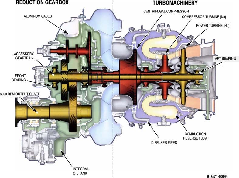
The turboshaft engines consist of a single-stage centrifugal compressor, a single-stage
compressor turbine, a single-stage power turbine, a reverse-flow annular combustion chamber,
and a reduction gearbox. A typical P&WC Model 207E turboshaft engine cross section is shown
below. Control of the turboshaft engines is accomplished through a FADEC. Hydro-mechanical
fuel metering unit (FMU) backup is also provided in the event of a FADEC failure. The FMU is
enclosed by a fuel-containment-housing for fuel/vapor containment safety considerations.
Report No. MD14021407-902TD 29 14 February 2014
USE OR DISCLOSURE OF DATA IN THIS TECHNICAL DESCRIPTION IS SUBJECT TO THE RESTRICTION ON THE COVER PAGE
MDHI PROPRIETARYMD 902 Explorer
Technical Description
P&WC Model 207E Turboshaft Engine Cross Section
The power turbine drives an output shaft through a two-stage reduction gearbox located at the
front of the engine which drives all engine-driven accessories (i.e., air conditioning compressor,
fuel pump, FMU, oil pump, starter-generator, permanent magnet alternator, etc.). Engine control
sensors are also located on the reduction gearbox to monitor low-pressure spool speed (Ng or
N1), power turbine spool speed, and engine torque sensor. The reduction gearbox also provides
mounting locations for an integral oil tank, the oil temperature sensor, oil pressure sensor, oil
pressure port, chip detector, oil filter, and oil filter impending bypass indicator. The engine oil
tank has a total capacity of 1.35 U.S. gallons (5.12 liters) and is provided with a filler
cap/dipstick and oil level sight glass. Turboshaft engine power through the reduction gearbox is
provided through drive shafts attached to the main rotor transmission.
A built-in turboshaft engine compressor water wash system is integrated with the turboshaft
engine installation. Turboshaft engine pressurized compressor wash system activation is
accomplished through the central compressor wash system ports located on the engine wash
panel. The Turboshaft engine compressor wash panel is located on top of the aircraft and on the
right-hand side engine inlet wall, adjacent to the right engine access door. Turboshaft engine
compressor wash system consists of stainless steel tubing routed such that a wash nozzle is
located over each engine inlet. The ports located on the engine wash panel are standard
aerospace fittings with lanyard secured protective covers.
Report No. MD14021407-902TD 30 14 February 2014
USE OR DISCLOSURE OF DATA IN THIS TECHNICAL DESCRIPTION IS SUBJECT TO THE RESTRICTION ON THE COVER PAGE
MDHI PROPRIETARYYou can also read