Study of a 12V Li-ion Battery Solution for Hybrid Vehicles - DANIEL CELA PATRIK ALERMAN Master's thesis in Electric Power Engineering Department ...
←
→
Page content transcription
If your browser does not render page correctly, please read the page content below
Study of a 12V Li-ion Battery
Solution for Hybrid Vehicles
Master’s thesis in Electric Power Engineering

DANIEL CELA
PATRIK ALERMAN

Department of Electrical Engineering
C HALMERS U NIVERSITY OF T ECHONOLOGY
Gothenburg, Sweden 2018
Master’s thesis 2018: EENX30

Study of a 12V Li-ion Battery Solution for
             Hybrid Vehicles

                 DANIEL CELA
               PATRIK ALERMAN

         Department of Electrical Engineering
        Division of Electric Power Engineering
       Chalmers University of Technology
               Gothenburg, Sweden 2018
Study of a 12V Li-ion Battery Solution for Hybrid Vehicles
DANIEL CELA, PATRIK ALERMAN

© DANIEL CELA, PATRIK ALERMAN, 2018.

Supervisor: Björn Isaksson, Senior System Engineer, CEVT AB
Examiner: Ola Carlsson, Professor of Electrical Engineering, Chalmers University
of Technology

Master’s Thesis 2018: EENX30
Department of Electrical Engineering
Division of Electric Power Engineering
Chalmers University of Technology
SE-412 96 Gothenburg
Telephone +46 31 772 1000

Typeset in LATEX
Gothenburg, Sweden 2018

                                         2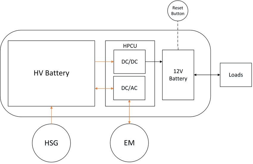
Study of a 12V Li-ion Battery Solution for Hybrid Vehicles
DANIEL CELA, PATRIK ALERMAN
Department of Electrical Power Engineering
Chalmers University of Technology

Abstract
Nowadays, the typical 12 volt battery chemistry in cars is lead-acid. There is the
possibility to replace this chemistry with a Li-ion technology in hybrid vehicles, due
to its potential beneficial features. Besides, there is a need of an extremely reliable
12V electric system in hybrid cars, not only for the current electric distribution
system in the car, but also due to the introduction of autonomous drive. Moreover,
since packaging space is a big issue in modern cars there is also a need to reduce
the number of components. Therefore, it is important to study the impact when
integrating the 12V Li-ion battery to be a part of the electric system as a power
source, including the power distribution system and loads, in order to improve the
utilization and performance of the battery. In this project the 12V Li-ion battery of
the hybrid vehicle is taken in to account to find a suitable battery available on the
market that can fulfill the specific requirements of the 12V electric system.

Keywords: Plug-in Hybrid Vehicle, 12V Li-ion Battery, Battery Management Sys-
tem, High Voltage, Battery Pack
Acknowledgements
I would like to especially thank our supervisor Björn Isaksson and the wonderful
team, thanks for the guidance during the project and help with all the laboratory
set up and testing. Our examiner, Ola Carlson deserves a thanks for his support
and invested time. Thanks to the Swedish Institute (SI) for sponsoring my master’s
studies in Sweden. Finally to my loved family.

                                                                    Daniel Cela
                                                       Gothenburg, Sweden. 2018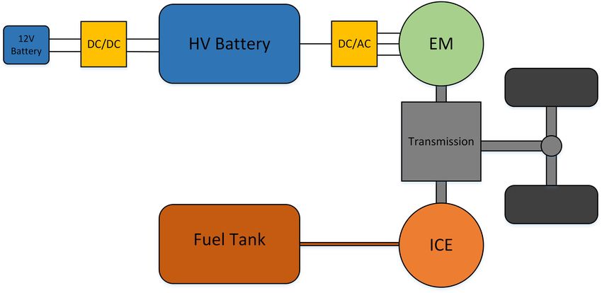
Acknowledgements
I would like to express my appreciation to Björn Isaksson for his valuable support
as a supervisor during this project, particularly for his enthusiasm to give his time
generously for laboratory tests. Besides our supervisor, I would like to thank all the
co-workers in the organization which have been involved in the project and for let-
ting us be able to visit their offices daily. Also, a special thanks to our examiner Ola
Carlson, his office door was always open whenever we had problem or a question.
Last but not least, I would like to thank you my one and only beloved family.

                                                                     Patrik Alerman
                                                           Gothenburg, Sweden. 2018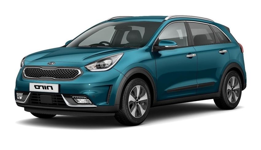
Definitions
Ampere hour (Ah), or amp hour for short, is the energy capacity of the battery. It
defines the number of amps or electric current that flows from a battery during one
hour [1].

C-rate describes the amount of charged/discharged-rate (current) which is relative
to the capacity of the battery for a certain time within specific voltage range [2].

Cold Cranking Amps (CCA) is a measurement which tells the capability of the
battery to start an engine in a cold environment. If a battery can maintain a mini-
mum voltage of 7.2 V during 30 seconds at -17.78 ◦ C, the number of amps from the
battery can be measured [3].

Curb weight is the weight of fuel tanked vehicle without any passengers, cargo or
other loads [4].

Gross weight is the total weight of the vehicle with passengers, cargo and other
loads [4].

Regenerative braking. A conventional vehicle’s kinetic energy is transformed into
heat loss during braking. Regenerative braking (or regeneration of braking energy)
allows some of these losses be captured, converted into electricity through the elec-
tric motor and stored in a battery. This stored electricity can provide extra power
for the electric motor during acceleration [5], [6], [7].

Reserve Capacity (RC) describes how long the battery will operate, in minutes,
for a fully charged battery to give 25 amps until the voltage reach 10.5 V at 26.67
◦
  C when the alternator is disconnected/failed [8], [9].

Table of contents

1 Introduction                                                                                                                              1
  1.1 Background . . . . .     .   .   .   .   .   .   .   .   .   .   .   .   .   .   .   .   .   .   .   .   .   .   .   .   .   .   .    1
  1.2 Aim . . . . . . . . .    .   .   .   .   .   .   .   .   .   .   .   .   .   .   .   .   .   .   .   .   .   .   .   .   .   .   .    1
  1.3 Problem Description      .   .   .   .   .   .   .   .   .   .   .   .   .   .   .   .   .   .   .   .   .   .   .   .   .   .   .    2
  1.4 Scope . . . . . . . .    .   .   .   .   .   .   .   .   .   .   .   .   .   .   .   .   .   .   .   .   .   .   .   .   .   .   .    3

2 Theory                                                                                                                                    4
  2.1 Battery Principles . . . . . . . . . . . . . . . . . . .                                     .   .   .   .   .   .   .   .   .   .    4
      2.1.1 Power & Energy Battery Content . . . . . .                                             .   .   .   .   .   .   .   .   .   .    5
      2.1.2 Battery Equivalent Circuit . . . . . . . . . .                                         .   .   .   .   .   .   .   .   .   .    5
  2.2 Battery Technologies . . . . . . . . . . . . . . . . .                                       .   .   .   .   .   .   .   .   .   .    6
      2.2.1 Lead-Acid Battery . . . . . . . . . . . . . .                                          .   .   .   .   .   .   .   .   .   .    6
      2.2.2 Li-Ion Battery . . . . . . . . . . . . . . . . .                                       .   .   .   .   .   .   .   .   .   .    9
  2.3 Battery Comparison and Sustainability . . . . . . .                                          .   .   .   .   .   .   .   .   .   .   10
  2.4 Hybrid Vehicles . . . . . . . . . . . . . . . . . . . .                                      .   .   .   .   .   .   .   .   .   .   13
      2.4.1 Hybrid Electric Vehicles . . . . . . . . . . .                                         .   .   .   .   .   .   .   .   .   .   13
      2.4.2 Plug-in Hybrid Electric Vehicles . . . . . . .                                         .   .   .   .   .   .   .   .   .   .   14
      2.4.3 Hybrid Powertrain Configurations . . . . . .                                           .   .   .   .   .   .   .   .   .   .   14
  2.5 HV-Battery Pack . . . . . . . . . . . . . . . . . . .                                        .   .   .   .   .   .   .   .   .   .   15
  2.6 Battery Utilization in Vehicles . . . . . . . . . . . .                                      .   .   .   .   .   .   .   .   .   .   16
  2.7 Benchmarking . . . . . . . . . . . . . . . . . . . . .                                       .   .   .   .   .   .   .   .   .   .   17
      2.7.1 Previous Technology of Battery Integration .                                           .   .   .   .   .   .   .   .   .   .   20
      2.7.2 Previous Specifications . . . . . . . . . . . .                                        .   .   .   .   .   .   .   .   .   .   21
  2.8 Autonomous Drive . . . . . . . . . . . . . . . . . .                                         .   .   .   .   .   .   .   .   .   .   21

3 12V Electric System & Battery Specifications                                                                                             24
  3.1 Electric System Overview in a Hybrid Vehicle . . . .                                             .   .   .   .   .   .   .   .   .   24
      3.1.1 Load Description . . . . . . . . . . . . . . . .                                           .   .   .   .   .   .   .   .   .   25
      3.1.2 Prioritizing 12V Loads . . . . . . . . . . . . .                                           .   .   .   .   .   .   .   .   .   26
  3.2 12V-System Requirements and Electrical Performance                                               .   .   .   .   .   .   .   .   .   26
      3.2.1 Loads . . . . . . . . . . . . . . . . . . . . . .                                          .   .   .   .   .   .   .   .   .   27
      3.2.2 DC/DC Converter . . . . . . . . . . . . . . .                                              .   .   .   .   .   .   .   .   .   27
      3.2.3 12V Battery . . . . . . . . . . . . . . . . . . .                                          .   .   .   .   .   .   .   .   .   28
  3.3 12V Battery Usage and Testing in a PHEV . . . . . .                                              .   .   .   .   .   .   .   .   .   29
      3.3.1 Starting Case . . . . . . . . . . . . . . . . . .                                          .   .   .   .   .   .   .   .   .   29
      3.3.2 Parking Case . . . . . . . . . . . . . . . . . .                                           .   .   .   .   .   .   .   .   .   31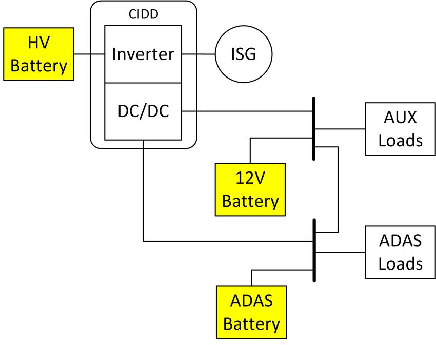
3.3.3 Normal Case . . . . . . . . . .     .   .   .   .   .   .   .   .   .   .   .   .   .   .   .   .   .   33
         3.3.4 Maximum Case . . . . . . . . .      .   .   .   .   .   .   .   .   .   .   .   .   .   .   .   .   .   33
         3.3.5 Emergency Case . . . . . . . .      .   .   .   .   .   .   .   .   .   .   .   .   .   .   .   .   .   34
   3.4   12V Li-Ion Battery Solution . . . . . .   .   .   .   .   .   .   .   .   .   .   .   .   .   .   .   .   .   34
         3.4.1 Battery Li-Ion Specifications . .   .   .   .   .   .   .   .   .   .   .   .   .   .   .   .   .   .   34
         3.4.2 Battery Calculations . . . . . .    .   .   .   .   .   .   .   .   .   .   .   .   .   .   .   .   .   37
         3.4.3 Battery Selection and Cost . . .    .   .   .   .   .   .   .   .   .   .   .   .   .   .   .   .   .   39
         3.4.4 BMS for the 12V Li-Ion Battery      .   .   .   .   .   .   .   .   .   .   .   .   .   .   .   .   .   43

4 Integration of the 12V Li-ion Battery & Autonomous Drive                                                             45
  4.1 Electrical System of Autonomous Drive . . . . . . . . . . . . . . . . .                                          45
       4.1.1 Electrical System Solution . . . . . . . . . . . . . . . . . . . .                                        47
       4.1.2 Consumption Estimation with Autonomous Drive . . . . . . .                                                48
  4.2 Battery Location Study and Losses in the Cable . . . . . . . . . . . .                                           50
       4.2.1 Impact of Cable Impedance Results for Current PHEV . . . .                                                51
  4.3 12V Li-Ion Section Solution . . . . . . . . . . . . . . . . . . . . . . .                                        53
       4.3.1 Cell Chemistry . . . . . . . . . . . . . . . . . . . . . . . . . .                                        53
       4.3.2 Cell Shape . . . . . . . . . . . . . . . . . . . . . . . . . . . . .                                      54
       4.3.3 Battery Pack Design . . . . . . . . . . . . . . . . . . . . . . .                                         56
       4.3.4 Packaging and Location . . . . . . . . . . . . . . . . . . . . .                                          58
  4.4 Complete System including 12V Li-Ion Battery and Autonomous Drive                                                63

5 Conclusion                                                                                                           64

6 Future Work                                                                                                          66
  6.1 Cranking Amps Result and Supercapacitor . . . . . . . . . . .                                    .   .   .   .   66
      6.1.1 Cranking Amps Test (CA) . . . . . . . . . . . . . . . .                                    .   .   .   .   66
      6.1.2 Supercapacitor Calculation . . . . . . . . . . . . . . . .                                 .   .   .   .   67
  6.2 Automatically Recharging the 12V Battery Every 10 Days . .                                       .   .   .   .   69
  6.3 Packaging Optimization of the 12V Battery with Larger Cells                                      .   .   .   .   69

References                                                                                                             70
1
Introduction
1.1 Background
Nowadays, there is an increasing demand of low emissions and environmentally
friendly vehicles. Thus, hybrid vehicles such as Hybrid Electric Vehicles (HEVs)
and Plug-in Hybrid Electric Vehicles (PHEVs) have been under development the
last years which consume less fossil energy. According to Navigant Consulting, the
HEVs represented three percent of the total number of passenger vehicles in 2017.
The vehicle’s auxiliary system has a voltage level of 12 V, that is powered up by a
Lead-acid (PbA) battery, which today is the most common battery in any vehicle
including HEVs and PHEVs. Not only current, but future generations of HEVs and
PHEVs include more electric loads and the vehicle electrification demands better
requirements from the 12V battery. Therefore, there is a need of a reliable 12V
system in hybrid vehicles for the present electric distribution system and new electric
loads such as: autonomous drive. Moreover, since packaging space is a big issue in
modern vehicles there is a need to reduce the number of components, the total vehicle
weight and the overall vehicle energy consumption. Hence, there is a possibility to
replace PbA battery with a Lithium-ion (Li-ion) battery and to integrate the 12V
battery within a future platform of HEVs/PHEVs.
1.2 Aim
The aim of this project is to find a suitable 12V Li-ion battery that can replace the
traditional Lead-acid battery in the low voltage system, analyze and estimate a 12V
Li-ion solution for the electric system when the autonomous drive is introduced, and
study the integration of a 12V battery in the future platform for HEVs & PHEVs.
11. Introduction
1.3 Problem Description
The 12V electric system is an important part of the vehicle. Currently, more re-
quirements are needed for the vehicle’s low voltage battery system to be fulfilled,
such as the autonomous drive system and present loads. Inside the vehicle there is
a space limitation together with the need of decreasing the vehicle’s total weight.
Therefore, the technology, size, weight and location of the 12V battery play a key
role in the vehicle’s performance.
In order to investigate and evaluate this project the next three sub-tasks are inves-
tigated:
• Study the availability on market of the 12V Li-ion batteries for vehicles.
• Analysis of the 12V system requirements with respect to power sources and
auxiliary loads including the introduction of the autonomous drive.
• Integration of a 12V Li-ion battery solution.
First, a market research is done to determine the availability of 12V Li-ion batteries.
Using market information of batteries and current offers from different suppliers, the
technical specifications of this type of battery are analyzed. The main advantage
of using Li-ion battery is the low weight and size compared with the traditional
Lead-acid battery. However, Li-ion battery is more expensive than PbA, thus the
cost of the solution is taken into account.
Furthermore, a benchmark analysis is performed in order to determine which cars
in the current market had adopted the 12V Li-ion battery technology. On the other
hand, the current requirements of the 12V system in hybrid vehicle are collected
and analyzed to perform a study of the electric power consumption of the loads in-
cluding technical data such as: rated voltage, current, power and working conditions.
Critical loads must be determined in order to find their energy requirements for
the worst driving scenario. It is important to find the limitations of the usage of the
12V battery along with the electric distribution system.
It is also important to analyze the power consumption of the low voltage system
when introducing the vehicle into autonomous drive mode. This study is needed in
order to investigate the reliability requirements of 12V system for the autonomous
drive. To be able to analyze the power distribution system in the HEV, an electric
system model is proposed.
Additionally, to complement the calculations, measurements are obtained from a
real-test of 12V system and current battery. Based on the results of the power
distribution system, a suitable Li-ion battery and its location in the vehicle is pro-
posed.
Finally, the integration of the 12V battery is analyzed, including different Li-ion
chemistries, battery shapes and location environments in the vehicle.
21. Introduction
1.4 Scope
This work considers the 12V battery, the auxiliary electric distribution system, and
the introduction of the autonomous drive for two types of hybrids vehicles - HEV
and PHEV - with parallel driveline system structure. Since, the loads and 12V
electric system are similar, the solution is valid for both, HEV and PHEV.
The main features of the current 12V Lead-acid battery and its performance in the
auxiliary system are analyzed from provided data, documentation and testing on
the vehicle. A market research of Li-ion battery is included, which shall fulfill the
requirements for the low voltage system in HEV/PHEV.
Besides, the introduction of the autonomous drive is taken into consideration, in-
cluding an analysis the 12V battery integration in the electric system. Test of the
12V system is carried out together with the battery, continuous and transient loads.
To simplify the 12V distribution system, a DC/DC (400V/12V) converter is treated
as a power source with a constant voltage, since it is a voltage controlled converter,
the results are not affected.
The cable impedance is measured to analyze the current losses when the battery is
placed in today’s location of the vehicle. Other locations are proposed in order to
decrease the cable losses.
A possible integration of the 12V system with the Energy Storage System (ESS)
and High Voltage (HV)-battery pack are studied, including an analyze of differ-
ent Li-ion chemistries, cell formats and battery locations. However, the powertrain
components are not examined because they are not a part of 12V system.
32
Theory
This section describes the theoretical background and general concepts of batteries
and chemistry technology. Additionally, hybrid vehicles as HEVs and PHEVs are
presented. Besides, the result of a benchmarking explains of which battery technol-
ogy is utilized in the hybrid vehicles today. Finally, autonomous drive technology is
introduced.
2.1 Battery Principles
A battery is a device which stores electrochemical energy and is able to deliver
into electrical energy. A basic battery contains three main components such as:
cathode, anode and electrolyte. Cathode or negative electrode is able to collect
electrons from the external circuit. Anode or positive electrode gives electrons to
the external circuit. The electrolyte is a material where the ions are transferred
from the anode to the cathode [10].
The main features must be taken into consideration when describing a battery such
as: State of Charge (SOC), temperature range, cycling, rate of discharge when not
in use, Deep of Discharge (DOD), C − rate, etc. [10], [11].
The SOC describes the charge content in the battery. It plays a key role for the
battery management of the hybrids and electric vehicles in order to keep the health
and safe operation of the battery. SOC can be defined as the ratio between the
remaining capacity (Cr ) and the nominal battery’s capacity (Cn ):
Cr
SOC = (2.1)
Cn
or Rt
to ηI(τ )dτ
SOC(t) = SOCt0 − (2.2)
Cn
where SOCt0 is the initial level of SOC, η is the efficiency of battery when charg-
ing/discharging and I is the current from/to the battery.
42. Theory
State of Health (SOH) can be defined as the ratio of the aged battery capac-
ity (Caged ) and the nominal battery’s capacity (Cn ). It describes the degree of
performance-degradation and can be used to estimate the battery remaining life-
time.
Caged
SOH = (2.3)
Cn
2.1.1 Power & Energy Battery Content
Batteries can be designed with a specific requirement for power and energy content.
The main impact of the optimization will be seen not only in the performance of the
battery, but also in its physical components and electrochemestry. According to [12]
the key design variables for a Li-ion battery are: electrode thickness, particle sizes,
porosity and conductivity. Therefore, depending on the battery application, it can
be power or energy optimized which has a direct impact in the final specifications
and properties of the battery.
A power optimized battery focuses on giving a high current for a short period of
time. This behaviour can also be obtained by a well-known passive element, a
capacitor. New vehicle technologies are adding a supercapacitor in order to deliver
high currents for transient loads. On the other hand, an energy optimized battery
allows to feed a load with relatively low current for long-term periods. For instance,
in a conventional vehicle application, the auxiliary battery of the car should fulfill
the energy content that allows the vehicle to be parked at least for 21 days , this
will be explained in detail in Chapter 3. However, a high current must be provided
for a few seconds to crank the vehicle described in Chapter 6.
2.1.2 Battery Equivalent Circuit
The battery can have different electrical models depending on the study or involved
application. A basic simple model of the battery is described in Figure 2.1, where
the internal battery voltage Voc (open circuit voltage) and the internal resistance
Ri are a function of SOC. This means that Voc and Ri are dependent on the SOC
and change correspondingly to it. The difference of the voltage between Voc and the
terminal voltage Vt leads a current Ic to flow. The current Ic can be bi-directional
if charging or discharging the battery [13].
52. Theory
Figure 2.1: Basic simple battery model including the internal battery voltage Voc and
the internal resistance Ri which are a function of SOC [13].
The terminal voltage Vt can be calculated as:
Vt = Voc (SOC) − Ri (SOC)Ic (2.4)
2.2 Battery Technologies
There are different battery technologies that can be used for the 12V electric system
in vehicles. The most common battery is the Lead-acid which has been under
development the last century, even continuing today. Nowadays, the Li-ion battery
technology is growing due to its advantages of energy content among others. A brief
description of these battery technologies are given below.
2.2.1 Lead-Acid Battery
The Lead-acid battery is based on the metallic material plumbum (Pb) which means
lead in Latin. This battery has the ability to provide a high inrush current, due
to a low internal impedance, wherefore it is mostly used as power source for the
ignition of a starter motor in automotive application. Also, due to its widely estab-
lishment and development the Lead-acid battery can be constructed to many forms
and voltage levels. However, the metal itself is toxic and heavy which have impacts
on the environment and complicates the battery construction. Due to the material’s
many features, the PbA battery is most convenient to use as an energy source for
starting, lightning and ignition (SLI) functions in vehicles [14]. In this work, an
investigation will be made to see if the 12V Lead-acid battery, as an energy storage
of the electrical system, can be replaced by another type of battery in the HEV &
PHEV.
The structure of the Lead-acid battery is a composition of two electrodes (or plates)
where the anode is based on the lead dioxide and the cathode on the metal lead.
These electrodes are separated from each other by sulfuric acid which is the elec-
trolyte that stands for the production of electrons at chemical reactions. Normally,
62. Theory
during discharging of the battery, sulphuric acid concentration in the electrolyte is
low when lead absorbing the sulfur. When recharging, the concentration is high as
the sulfur from the lead returns back to the electrolyte [14], [15]. When the PbA
battery is fully charged, six cells produce a voltage. Each cell provides 2.0 V, in
total it will be 12 V which is the nominal voltage of a 12V battery [16]. However,
according to [17] the electrical 12V system in vehicle applications are normally 12.6
V at no load and with load approximately 14 V.
Depending on the battery application, a Lead-Acid battery can be designed in two
different main types [18]:
• Starting battery (for SLI functions) - due to thinner plates and their material
properties, the electrons are able to move faster in the battery to quickly
generate a higher inrush current in order to start (cranking) an engine.
• Deep cycle battery - due to thicker plates they are fewer, which give the battery
less inrush current, on other hand it can store energy during a longer period
and handle many discharging cycles.
These types have several variations when it comes to PbA batteries, which are
described in more detail in section 2.2.1.1.
2.2.1.1 Development of PbA Battery
Why Lead-Acid is still in used in batteries in conventional cars and in HEVs and
PHEVs likewise depends on its history development. At the start, the PbA battery
was implementing as a starting battery of the first developed electrical systems in
vehicles for SLI functions. In the 1950s, the voltage level of the systems was se-
lected to 12 V, ever since then there have been a lot of improvements of the battery
[17]. The coming five decades the Lead-acid battery has developed, and still does, to
many different versions accordingly to the requirements from the auto industry. The
development has been going in two different directions, which have created two main
groups of PbA-batteries, such as: Flooded and Valve Regulated Lead-Acid (VRLA),
also known as Sealed Lead-Acid (SLA) [19]. The development of the Lead-acid bat-
tery is depicted in Figure 2.2.
The first batteries were Flooded (Wet cells) batteries which means that the elec-
trolyte inside of the battery is in liquid form. Due to its open design, liquid and gas
are leaked which is an environmental problem. This requires the electrolyte level
is checked and water is added to the loss electrolyte solution regularly. Though,
this kind of battery is still common on the market due to its high rate charge for a
low price [20]. A similar battery to flooded batteries is Enhanced Flooded Battery
(EFB) which has thicker plates which gain faster DOD and longer cycles [19].
Next, the VRLA battery was developed as sealed-constructed battery. Due to its
design, liquid and gases in operation would not leak, hence the battery would be
maintenance free. The VRLA battery can be divided into two categories - gel elec-
trolyte battery (Gel cell) and Absorbed Glass Mat (AGM). The gel cell was designed
72. Theory
Figure 2.2: The development of the Lead-acid battery.
with a gelatinized electrolyte solution, which allows it to be in any position and be
resistance against vibration. However, they have limited applications due to the
many advantages of AGM. In AGM batteries the gelatin have been replaced by
fiber glass. This allows the battery to directly absorbs the electrolyte. An extension
of AGM is Advanced AGM (AGM+), which has compressed plates which allows a
battery with small design size and high capacity [19], [21].
The VRLA was further developed when carbon was introduced, which becomes an
advanced lead-carbon. In some cases, according to the U.S. Department of Energy,
the Lead-carbon battery is equal or better than Li-ion and NiMH batteries in per-
formance and are more economic to be utilized. The next coming generation of
Lead-acid batteries are Advanced Lead-Acid Battery Consortium (ALABC), which
will combine increased efficiency and low costs of HEV to meet the sustainable and
economic demands.
The development of the battery has led to many types of PbA batteries, which
consecutively contributed to its standardization as 12V battery. Now, it is the most
common battery to use for the vehicle’s electric system. Therefore, is an ordinary
sight within the auto manufacturers [21].
In this work, the current 12V battery that is used in the electric low voltage system of
the investigated HEV & PHEV is a VRLA battery that is based on AGM-technology.
Therefore, this particularly battery will be study more deeply. Table 2.1 represents
the specifications of that battery, or so called the battery capacity label.
82. Theory
Table 2.1: Lead Acid battery capacity label.
Feature HEV & PHEV
Type H6 (L3)
Nominal voltage (V) 12
Battery Capacity (Ah) 70 (20HR)
Rated Capacity (min) 120
CCA @ -18◦ C (A) 760
Charge Acceptance 5I20
Weight (kg) 21.3
Dimensions (mm) 278 x 175 x 190
Where the geometrical dimensions of the battery are:
• Length = 278 mm
• Width = 175 mm
• Height = 190 mm
2.2.2 Li-Ion Battery
Lithium is the lightest metal, under normal conditions, among the chemicals ele-
ments. The electrochemical properties of the lithium-based battery gives the po-
tential to achieve high power and energy densities. Currently, it is widely used in
several electronic applications and electric vehicles. Lithium batteries can be mod-
eled and customized according to specific requirements. Different combination of
types, materials and structures for Li-ion batteries can be selected in order to have
a suitable battery for electric cars. The energy density is increased with high open
circuit voltage and low weight, the SOC where the battery can be cycled is wide.
The main disadvantage of this technology is that in low temperatures (2. Theory
others. The Li-ion chemistry still continues under development and the automotive
industry is been adopting this technology. There are several Lithium-ion chemistries
that are used in different applications. The main chemistries within automotive
industry are described below [22], [23]:
• Lithium Iron Phosphate (LiFePO4 or LFP)
This chemistry uses phosphate as a cathode material and is the most common
technology used to replace the SLI lead-acid battery in vehicles. In order to get
12.8V from the this battery 4 cells in series are required. The main advantages
to used this chemistry are: high current rating, long cycle life, good thermal
stability, enhanced safety and tolerance. The typical temperature range is -20
◦
C to 70 ◦ C. Besides, LFP is one of the safest chemistry in the Li-ion family,
since it is highly stable during undesired conditions such as: short circuit,
overcharge or overcurrent.
• Lithium Nickel Manganese Cobalt Oxide (LiNiMnCoO2 or NMC)
The most common cathode material is nickel-manganese-cobalt, by combining
these three elements the battery performance is achieved. Therefore, there are
many combinations that can take the qualities of each element for different
applications such as: electromobility, medical devices, industrial. The main
features of this chemistry are: high capacity, specific power and popular in the
market for many applications [22].
• Lithium Nickel Cobalt Aluminum Oxide (LiNiCoAlO2 or NCA)
By adding aluminum to lithium-nickel-oxide, it is possible to develop a high
stable chemistry. This one is so called NCA, its characteristics are similar
to NMC, such as high specific energy, relative high specific power and long
lifetime. Though, NCA comes with a high cost and due to a low thermal
runaway this chemistry is less safety compare to other Li-ion chemistries [23].
• Lithium Titanate (Li4Ti5O12 or LTO)
The best qualities of this chemistry are: long life, fast charge, wide temperature
range. Besides, it is included in the safest Li-ion family due to its high thermal
stability under high temperatures. On the other hand, it has a relatively high
cost and low specific energy content. The common applications are: electric
powertrain, lighting, UPS, etc. [23].
Current research continues developing Li-ion batteries for automotive industry in
order to increase their performance and features, but also in aims of reducing the
total cost.
2.3 Battery Comparison and Sustainability
Since the Li-ion and Lead-acid battery are based on two different chemistries, it is
important two distinguish the advantages and disadvantages of each battery. This
102. Theory
section describes the comparison of them and their impact on the environment.
Except for the low price, the PbA-battery can be recycled easily. Almost all com-
ponents, like lead, sulfuric acid and plastics, in any kind of Lead-acid battery can
be reused. Additionally, the manufacturing costs of new batteries are lower when
utilizing reused material because less energy is required, which also means reduced
pollution of CO2 from the auto industry. Investigations by U.S. Department of
Energy show the emissions of Lead-acid batteries are low during the production
compared to other kind of batteries as shown in Figure 2.3 [21].
Figure 2.3: Average CO2 emissions of different battery chemistries [21].
Besides, Lead-acid batteries comes in many variations (size, voltage level, etc.), they
have a flexible design factor. Moreover, the internal impedance is low in the batter-
ies which allow them to supply a high inrush current.
Despite the beneficial features of PbA, there are some drawbacks. According to
the periodic table, the material has a density of 11.3 g/cm3 , which is much higher
than it is for lithium, explaining why it is so heavy [24]. Hence, less specific energy
and power which means reduced battery capacity. Even if the battery is recycled
friendly, its acid is toxic and harmful for environment and people at leakages.
Lithium has a small density (0.534 g/cm3 ), which means it can have a higher specific
energy density (Wh per kilogram) [25]. This also involves reduced size and weight
of a Li-ion battery. Figure 2.4 shows how the density of lithium is higher compare
to other chemistries [26].
112. Theory
Figure 2.4: Battery density comparison. Nominal battery energy per unit volume vs.
nominal battery energy per unit of mass [26].
Otherwise, the biggest issue for the Li-ion chemistry, at least for today, it is ex-
pensive and difficult to be recycled. However, according to [27], in 2018, scientists
at Chalmers University of Technology have found a method of how lithium can be
recycled. The method implies different applied chemistries that are separating the
disassembled battery’s metals. Though, this method is still expensive, the univer-
sity and the battery company Northvolt are in collaboration in order to reduce the
recycled cost.
As the use of electric vehicles is rising, the demand of lithium is increasing. Globally,
within a decade, the manufacturing of lithium will grow dramatically. The battery
manufactures are planning to establish new facilities which can give a total capacity
growth from 28 GWh per year to 217 GWh per year [27].
Besides the manufacturing development, the mining of lithium will also increase.
Although, this does not mean lithium as a raw material will end. There are large
assets of lithium over the world and can be prospected in mines, dehydrated lakes
and even from sea water, which can be considered as an infinitive source [28].
Table 2.2 shows the different battery chemistry properties between lead-acid and
li-ion.
122. Theory
Table 2.2: PbA vs. Li-ion chemistry and general specifications [23], [26], [29], [30], [31].
Lead Acid Lithium-ion
LiFePO4 LiNiMnCoO2
Flooded AGM VRLA
(LFP) (NMC)
Specific
30 40 90-120 150-220
Energy (Wh/kg)
Specific
100-200 100-200 500-8000 >500
Power (W/kg)
Number
200-1000 200-650 1000-4000 1000-4000
of cycles to 80% SOH
Temperature
-40 to +55 -15 to +50 -30 to +60 -20 to +60
Range (◦ C)
Useful
50 50 >80 >80
capacity
Self-discharge
3-4 3-4 2-32. Theory
powered by the stored electric energy from a High Voltage (HV) battery-pack. The
battery cannot be plugged-in and charged remotely from an electric outlet, only
charged with regenerative braking or from the ICE when the vehicle is in movement.
The combination of the two engines makes the ICE fuel efficient which reduce fuel
costs and pollution [5], [32], [33].
2.4.2 Plug-in Hybrid Electric Vehicles
PHEVs are also known as Extended Range Electric Vehicles (EREVs). It consumes
fossil fuels for an ICE and electric energy from a HV battery for an EM. This large
battery can be charged from an electric power source in three ways. The battery can
be charged by the PHEV is plugged-in to an external electric outlet, by regenerative
braking and by the ICE. Due to the battery size and the different ways of recharging
it is possible to drive only in electric mode. Besides, a longer driving distance is less
dependent on fuel. Therefore, the impact on the environment and fuel costs are less
than for HEV [32], [34].
2.4.3 Hybrid Powertrain Configurations
A powertrain (driveline or drivetrain) of a hybrid vehicle is the system of components
which deliver power to the wheels. The powertrain can be categorized into three
main classes: series hybrid, parallel hybrid and series-parallel hybrid. This section
describes the configuration of each one of them [35]. For this work, parallel HEV &
PHEV is studied.
• Series HEVs: This is the simplest configuration where the battery and the ICE
are connected to the EM, which is subsequently, mechanical linked with the
wheels through the driveline. A computer decides how much energy should be
delivered to the EM, it can either gets its power from the battery, the ICE in
generator-mode or both.
• Parallel HEVs: In this configuration, shown in Figure 2.5, the ICE and the
EM have their own driveline which both are directly connected to the wheels
through the transmission. Since the wheels are directly connected to the EM
there is no conversion losses. The engines are operating separately or simul-
taneously. Regenerative braking allows a reduced size of the HV battery and
when it needs to be recharged the ICE will work as an alternator (generator) to
supply power. The 12V battery in the investigated HEV & PHEV is charged
by a HV battery via a DC/DC converter.
142. Theory
Figure 2.5: The parallel HEV configuration [36].
• Series-parallel HEVs: The configuration is a combination between the power-
trains series and parallel. The ICE can either propels the wheels directly, or
be disconnected and let the EM supply power to the wheels.
2.5 HV-Battery Pack
Today’s platform consists of a HV battery that is special designed accordingly to
the investigated hybrid vehicle. The battery in the PHEV is power optimized and
has 24 cells more in series compare to the HEV. The PHEV has an energy optimized
HV-battery with 8 connected modules where each module has 12 cells in series, i.e.
96 cells in series in total. The cell is designed with a prismatic form and has a
chemistry of NMC 811. Each cell has a voltage of 3.6 V, which give a total voltage
of 345.6 V. The battery pack is completed sealed under the rear seats in the vehi-
cle. The total weight of the HV-battery pack is 146 kg, whereof 90 kg belongs to
the modules and the rest to various plates, covers, pads, connectors, trays, sealers,
systems and units. The specifications of the cell and the battery pack of the PHEV
can be seen in Table 2.3 and Table 2.4 respectively.
Table 2.3: The specifications of the NCM 811 cell.
Feature Cell Data
Cell chemistry NCM 811
Cell type Prismatic
Nominal Voltage (V) 3.6
Nominal cell capacity (Ah) 51
152. Theory
Table 2.4: The specifications of the HV-battery pack.
Feature Pack Data
Number of cells series 96
Number of cells parallel 1
Number of modules 8
SOCmax (%) 95
SOCmin (%) 15
Pack capacity (Ah) 51
Nominal Pack voltage (V) 345.6
Total Energy (kWh) 17.63
Usable energy (kWh) 14.10
Power output (kW) 100
Weight (kg) 146
Operation range (◦ C) -40 to +55
Each module is temperature measured by a Battery Management Unit (BMU) in
the 12V system via the low voltage harness. The HV-battery pack can be cooled
down due to the modules are connected with thermal pads which leads the heat
from the pack. For maintenance of the HV-battery, it is crucial to disconnect the
contactors from it to avoid personal damages. There are three ways to open the
contactors, through HV-battery, a signal from 12V battery or 12V system.
2.6 Battery Utilization in Vehicles
The motor and the electric system of a vehicle are dependent on the 12V battery
to run. However, the battery is used differently in an Internal Combustion Engine
Vehicle (ICEV) compare to a hybrid vehicle, e.g. a HEV, regardless of powertrain
design. This can be study by letting the motor of each vehicle be on and off. The
section describes the differences between them [37].
ICEV - Motor On: The 12V battery is designed to produce a large current (in-
rush current) to start the vehicle (ignite the motor). For how long and how much
power the battery will deliver counts on its RC and CCA ratings. As soon the motor
is running, an alternator is providing power to the low voltage system including the
12V battery which can keep its voltage level.
HEV - Motor On: Less inrush current is needed to start the motor, because a
DC/DC-converter is used instead of an alternator. Though, the motor requires sus-
tain energy during a longer operation time from the battery. It must also handle
low discharging levels and recharging regularly. No extra loads are added when the
motor is on, i.e. same loads as before when the motor was turned off.
ICEV - Motor Off: Low 12V load, most of the components are not dependent
162. Theory
on the battery when the vehicle is not running.
HEV - Motor Off: High 12V load, even if the motor is off the computer systems
are still running to remain vehicle is ready to be turned on, the communications of
charging and the BMS.
Since the battery in a HEV requires many cycles and less inruch currents, the re-
quirements differs for the 12V system in HEV compared to ICEV. Starting batteries
of PbA is suitable in an ICEV because, their high CCA rate, they can generate a
high inrush current (discharge) and due to its low number of cycles it has a long
lifetime, which is more economic over time. However, this kind of battery would not
work properly in HEV that demands many repetitive cycles, which would damage
the battery quickly. On the other hand, because a deep cycle battery of PbA has
a high RC rate it would sustain many and deep discharges without destroying the
battery [37], [38].
The 12V system in the hybrid vehicle demands a battery which is preferable smaller,
lighter and can candle a large number of cycles (high RC). Additionally, a battery
that has low losses of the capacity and degradation. The Li-ion battery have these
features, which would be appropriate to adapt in the HEV & PHEV.
2.7 Benchmarking
This section presents vehicles where a 12V Li-ion battery has been already imple-
mented, its battery specifications data and how the battery is integrated in the
electric system.
In the investigated market analysis, of which cars are using a 12V Li-ion battery
for the auxiliary system, it is shown that most automobile manufacturers have not
adapting to the Li-ion technology yet.
According to John Voelcker, the first vehicle that uses a Li-ion battery is Toyota
Vitz CVT 4, only available in Japan. This subcompact(B), conventional vehicle uses
a 12Ah Li-ion battery with 4 cells, mainly to power up the electronic accessories and
restart the ICE after idle stop [39].
Table 2.5 represents the type of battery that is used for each car model. All the
HEVs from Toyota are represented as one vehicle model. In total there are 20 car
models, whereof 16 having a Lead-acid battery and 4 (the gray rows in the table)
are using a Li-ion battery. Tesla Roadster version 1.5 does not have a 12V battery
whatsoever and using the HV battery as an energy source for the low voltage sys-
tem [40]. For some of the Porsche HEV models, it is optional to change the 12V
battery from Lead-acid to Li-ion technology [41]. The South Korean manufactures
of the HEVs: Hyundai Ioniq Hybrid and Kia Niro, see them in Figure 2.6a and 2.6b
respectively, have both decided to use 12V Li-ion battery which is integrated as a
section of HV-battery pack. These models were developed from a common platform
which is notable in their car features [42].
172. Theory
The focus will be on Hyundai Ioniq Hybrid and Kia Niro, due to they are the latest
cars that are using 12V Li-ion battery on the market and the investigated HEV&
PHEV has similar car features as them. In spite of the models from Porsche or
Toyota Vitz CVT 4 are using Li-ion batteries, they will not be examined. Because,
Porsche offers two different chemistries, while it was of interested to study a 12V
Li-ion battery. The Toyota model has a Li-ion battery, however that car is consider
to be too small, hence the battery requirements would be different and therefore the
Toyota Vitz CVT 4 is not comparable with the HEV & PHEV.
(a) Hyundai Ioniq Hybrid [43]. (b) Kira Niro [44].
Figure 2.6: Two of the few car models that have adapting to the Li-ion technology for
the 12V battery.
Hyundai Ioniq Hybrid is a HEV with a Permanent Magnet Synchronous Motor
(PMSM) of a maximum power of 32 kW (43 hp) and 169 Nm in torque, which is
supplied by a 240V Li-ion polymer battery with a capacity of 1.56 kWh. The EM
can by itself reach 121 km/h (75mph) in vehicle velocity. In hybrid system mode,
both engines can deliver a total output power of 104 kW (139 hp). The vehicle has a
curb weight of 1359 kg [43]. In USA, the latest Hyundai Ioniq Hybrid model become
one of the first manufactured car with a low voltage system that was powered by
a 12V Li-ion battery. A section of the 240V HV-battery pack was left open which
is the placement of the 12V starter battery. Both of these batteries are mounted
together under the rear seats, though they are operating separately. Due to that
reason, they are interconnected permanently. This allows the driver, if the 12V bat-
tery is discharged and hence not able to start the motor correctly, to use the 240V
battery to recharge the 12V battery. This happens by pressing a reset button inside
of the cab. Considering the weight of the 12V Li-ion battery that is 11.79 kg and its
small size, 2 % of the cargo can be extended compare to the other two models in the
same series - Ioniq Plug-in and Ioniq Electric, which both are using 12V Lead-acid
battery that are located in different areas [45].
From the latest car model in the USA, a small 12V Li-ion battery, under the rear
seats, has been integrated into a 240V constructed based Li-ion Polymer HV-battery
pack of Kia Niro (HEV). This allows the driver to use the big battery’s energy to
recharge the small one by pressing a reset button. The HV battery, with its capacity
of 6.5 Ah and 1.56 kWh. It also provides power to a PMSM that has power output
182. Theory
Table 2.5: Vehicle models that are using a Li-ion or PbA battery in the 12V electric
system.
Vehicle
Brand Model Battery Location
Type
Hyundai loniq hybrid
HEV Li-ion Under rear seat
[45] (modelyear 2017)
Niro (modelyear
Kia [42] HEV Li-ion Under rear seat
2018)
Toyota
Vitz CVT 4 EV Li-ion -
[39]
911 GT3, 911 GT3
Porsche
RS, and Boxster HEV Li-ion -
[41], [46]
Spyder
No 12V
Tesla [40] Roadster v1.5 EV -
Battery
Hyundai
loniq electric plus PHEV PbA Rear cargo area
[45]
Hyundai
loniq electric EV PbA Rear cargo area
[45]
Kia Niro (upto 2017) HEV PbA -
Kia Niro PHEV PbA Under rear seat
Kia [47] Optima SW PHEV PbA Trunk wall
Mitsubishi
Outlander PHEV PbA Rear cargo area
[48]
Nissan [49] Leaf EV PbA Front hood
Smart ED
ED EV PbA -
[50], [51]
Tesla [52] S EV PbA -
Tesla [53],
X EV PbA -
[54]
Tesla [55] Roadster 2.X EV PbA -
Tesla [56] Model 3 EV PbA -
Toyota All hybrids HEV/PHEV PbA -
Volkswagen
Egolf EV PbA Front hood
[57]
BMW [58] i3 EV PbA Rear cargo area
of 32 kW (43 hp) and a torque of 169 Nm. In hybrid operation the vehicle can
accomplish 104 kW (139 hp). The curb weight and the gross weight of the vehicle
are 1409 kg and 1850 kg respectively. Depending on the vehicle’s equipment, the
vehicle is both a HEV and PHEV [42], [44].
The features of the 12V Li-ion battery and its auxiliary system in the Hyundai
Ioniq Hybrid and Kia Niro (HEV) will be compared to the battery solution for the
investigated HEV & PHEV.
192. Theory
2.7.1 Previous Technology of Battery Integration
In the platform of Hyundai Ioniq Hybrid and Kira Niro, an adaption of a lighter
and smaller 12V battery has been made to reduce the fuel consumption and increase
the performance of the vehicle. Also, in order to decrease the cable impedance of
the electrical system, the low voltage battery must be close to the HV battery.
Therefore, under the rear seats in theses vehicles, a 12V Li-ion battery is integrated
with the HV battery together in one single box, which is known as the HV-battery
pack, according to Figure 2.7.
Figure 2.7: Integration of the 12V battery [59].
While the 12V battery powers the auxiliary loads of the low voltage system, the
HV battery stores and supplies electric energy to the EM. The motor converts from
electrical to mechanical energy for the traction of the vehicle. Between the batteries
there is a unit called Hybrid Power Control Unit (HPCU) which controls the current
supply from the HV battery. This unit is one common housing of one DC/DC
converter, or Low Power DC/DC-Converter (LDC), and one DC/AC-Inverter. The
converter transfers the power from high voltage to low voltage to supply the 12V
battery and the auxiliary loads. The inverter transfers the power from DC to AC for
supplying the EM. Also, inversion form AC to DC is done to charge the HV battery
when the EM is operating as a generator (eg. at regenerative braking). The HV
battery is also charged while driving at HEV-mode by a Hybrid Starter Generator
(HSG). This generator can also restart the ICE. In a case of fully discharged 12V
battery, a reset button is available in the driver’s compartment which can be used
to recharge the battery from the HV battery. The orange colorized lines shown in
Figure 2.7 represents the high voltage cables according to SAE standards. These are
cabling under the floor and connect HV-battery pack, HCPU and EM with other
202. Theory
components in the front hood [59].
2.7.2 Previous Specifications
The two car models that are using a 12V Li-ion battery are described. The specifi-
cations for each one of them are presented before and after adapting to the Li-ion
technology. Table 2.6 shows the battery capacity label of the 12V Lead-acid battery
in the mentioned HEVs [60], [61].
Table 2.6: Lead-acid battery capacity label.
Feature Ioniq Hybrid Niro (HEV) Niro (PHEV)
Battery name AGM60L-DIN AGM90L-DIN CMF45L-DIN
Nominal voltage 12V 12V 12V
Nominal capacity 60Ah (20HR) 90Ah (20HR) 45Ah (20HR)
Nominal RC 100min 170min 80min
CCA by SAE* 640CCA 850CCA 410CCA
CCA by EN* 512A 680A 410A
Table 2.7 presents the battery specifications of the 12V Li-ion battery that is used
in the latest Kia Niro HEV-model. It is assumed that similar specifications can be
found in the Hyundai Ioniq Hybrid, since this vehicle and Kia Niro are built on the
same platform.
Table 2.7: Li-ion battery capacity label in Kia Niro (HEV).
Feature Kia Niro (HEV)
Model name of battery Lithium ion Polymer Battery (LIPB)
Nominal voltage [V] 12.8 V
The nominal capacity [Ah] 30Ah (20HR)
Number of cells (EA) 8
Cell voltage Deviation [mV] 40mV or less
Operation Voltage [V] 10-14.8V
2.8 Autonomous Drive
Nowadays, most of the previous vehicle models have been implemented with dif-
ferent intelligent driver assist functions, which can help the driver to control the
vehicle’s speed and avoiding accidents. The technology within the industry is going
to a driverless future. This has resulted to new auto-competitors like Uber and
212. Theory
Alphabet and electric vehicle maker like Tesla are testing autonomous driving func-
tions. Traditional automotive makers, such as Volvo predicts the that no one will
ever crash when driving one of their cars the year 2020 [62]. The same year, accord-
ing to an announcement by Nissan, a self-driven car will be delivered by them [63].
A human has the ability to observe the surrounding environment, by scanning and
collecting information from it, and an action can be made. A self-driven vehicle or
a vehicle with autonomous drive is working according to the same principle [64].
The vehicle knows its surroundings with its moving objects in the traffic by several
sensors or microchips such as lasers, cameras and GPS-units. Today, some of these
sensors have the capability to let a self-driven vehicle in test to drive with or without
a driver [63], [64]. Therefore, the grade of autonomous drive is usually described in
six different autonomy levels, according to SAE International, as seen in Figure 2.8.
The first level explains the vehicle control before entering into the autonomous-levels
[62], [65].
Figure 2.8: The levels of autonomous drive [62], [65].
Level 0 - No Automation
The human driver has complete control of the vehicle, including accelerate/brake
and steering, during the whole driving-cycle.
Level 1 - Drive Assistance
A driver assistance system supports the driver to either accelerate/brake or steering
in certain traffic situations. Otherwise, the human is handle all driving conditions.
Level 2 - Partial Automation
Several driver assistance systems controls the acceleration/braking and steering of
the vehicle. For instance, make sure the vehicle is on the route, brakes for obstacles
and regulate the speed with an adaptive cruise control. Otherwise, the human driver
is handling all driving conditions.
Level 3- Conditional Automation
The vehicle is driving by itself in certain traffic conditions, e.g. on highways and in
traffic jams. Otherwise, it is expected that the human driver will act and intervene
when the autonomous driving-function encounters problems.
Level 4 - High Automation
The vehicle is driving itself in most traffic conditions. The autonomous system can
handle and solve almost any kind of traffic situation. For example, when the vehicle
is leaving areas or roads where autonomous drive is activated, the system requests
222. Theory
the driver to take over the vehicle. If the driver does not take the vehicle’s control,
the autonomous drive will handle the situation by itself.
Level 5 - Full Automation
The vehicle can handle any kind of traffic situation and the human driver does
not have to act nor intervene. The vehicle is driven by itself, i.e. the vehicle is
performing a completely autonomous drive.
233
12V Electric System & Battery
Specifications
This chapter describes the 12V electric system in a hybrid vehicle, which has three
main components: 12V battery, loads (continuous and transients) and DC/DC con-
verter. The low voltage system has the same characteristics for both HEV & PHEV
which are based on the same vehicle’s platform. Therefore, they will be referred as
one hybrid vehicle called HEV/PHEV.
3.1 Electric System Overview in a Hybrid Vehicle
The electrification of the vehicle has been increasing the last years. Thus, more
electric loads demands more electricity and increasing the reliability of the system.
Usually, the HEV/PHEV has the electric system running at two different voltages,
12V and 400V. There are some cars that are migrating from 12 V to 48 V for the
low voltage system, though it is not of interest in this project.
The so called High Voltage (HV) electric system, manages a voltage level around
400 V (it may differ from different vehicle’s manufactures that can use voltage levels
up to 600 V). Generally, this system consists of a HV-battery pack mainly used for
the vehicle’s propulsion, HV cables, a power inverter and a DC/DC converter. On
the other hand, the 12 V electric system manages the operation of all the auxiliary
loads, Electronic Control Units (ECUs) & devices to control and protect the HV
system.
The correct operation of the vehicle including the HV electric system depends on the
reliability of 12 V system, thus its importance. The low voltage system consists of
electric loads, a DC/DC converter (400 V to 12 V) and a 12V battery, conventionally
based on Lead-acid technology. This project focuses on the study of the 12 V power
distribution system including the battery for the auxiliary system. The low voltage
loads are described by using HEV/PHEV model on the market. The low voltage
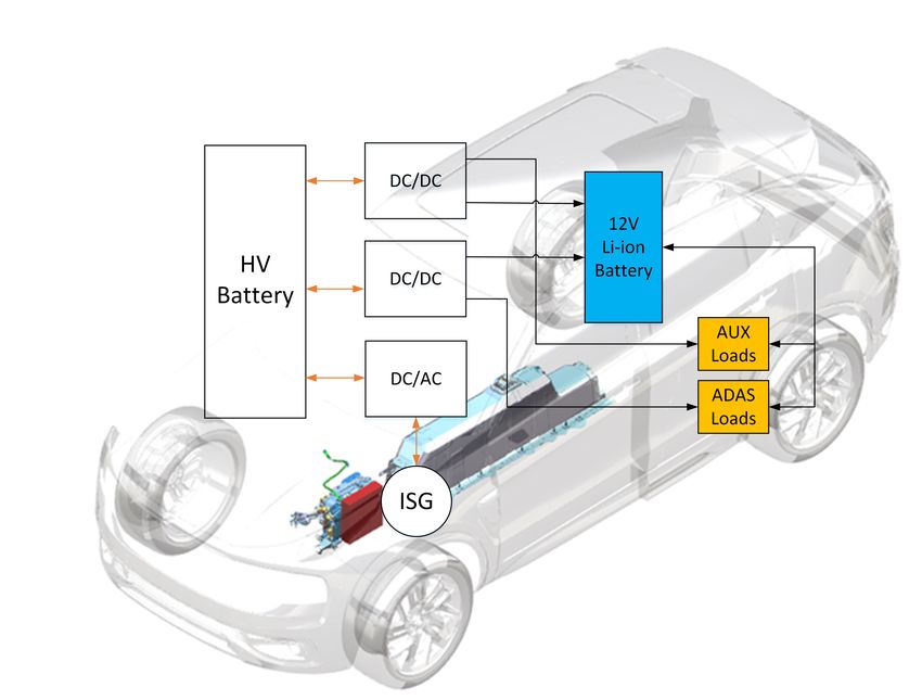
electric system is shown in Figure 3.1.
243. 12V Electric System & Battery Specifications
Figure 3.1: Low voltage electric power distribution system of common HEV/PHEV.
The DC/DC converter decreases the voltage level from 400 V to 12 V to feed power
to the low voltage circuit. The converter is a voltage controlled device, which means
the voltage will be stable on its operating current range. The battery used for
the investigated HEV/PHEV is a Lead-acid AGM H6 70 Ah (full specifications
mentioned in section 2.2.1.1). The loads can be supplied by two power sources, the
converter will provide power to the low voltage loads when the vehicle is turned
on (running mode). The 12V battery provides power to the loads when the car is
standstill, for starting the computers and controllers of the car before the ignition. It
is important to describe that the main difference of the conventional cars compared
with the HEV/PHEV is that the start/stop function energy requirements is provided
by the HV electric system.
3.1.1 Load Description
In a conventional hybrid vehicle the electric loads represent hundreds of different
devices with a wide range of applications and functionalities. The 12V electric loads
are divided in several subsystems such as: active safety, ambient light, body, cli-
mate, exterior lights, heater, infotainment, interior lights, power train, restraints
and power outlets. The loads can be categorized into two different characteristics -
continuous loads and transient loads.
Continuous loads
The continuous loads are consuming a constant current over a long period of time.
An example of continuous loads are ECUs which are small electronic computers in
the 12V electric system.
Transient loads
The transient loads are consuming high power over a short period of time. Braking
and steering systems are the most power consuming in the 12V electric system.
• Electric Power Assisted Steering (EPAS) is an electric power unit in the vehi-
253. 12V Electric System & Battery Specifications
cle’s system which supports the steering function of the vehicle [66].
• Vehicle Dynamics Domain Master (VDDM) is a module in the braking system
which can avoid the wheels from slipping [67].
• Brake Boost Module (BBM) is an electric pump in the braking system that
gives a certain pressure based on the position of the break pedal [68].
The 12V loads are analysed and prioritized according its importance focusing on the
safety and reliability of the electric system.
3.1.2 Prioritizing 12V Loads
There are electric loads that are significantly more important than others to make
the basic operation possible and enable the primary functions of the vehicle. The
electric loads in the low voltage system were prioritized by taking into consideration
the following aspects:
• Vehicle’s safety operation.
• Continuous operation loads to run the vehicle’s computer (controllers).
• Transient loads e.g. steering, braking.
• Vehicle’s performance.
Therefore, the most relevant loads to be considered are: EPAS, VDDM and BBM.
3.2 12V-System Requirements and Electrical Per-
formance
In order to describe the specifications of the 12V battery for HEV/PHEV based on
the vehicle platform, the requirements of the electric system are analyzed including
the behaviour of continuous and transient loads, the DC/DC converter, the electric
system performance and test data.
The 12V system shall always provide electric power and therefore ensure function-
ality, security and reliability of the system’s driving mode and battery lifetime. The
vehicle shall be safely drive regardless of the 12 V supply source. The system has
a nominal voltage range between 12.5 V and 15.5 V. In normal case, the electrical
distribution system has a total maximum voltage drop which is less than 1.5 V.
The 12V electric system considers not only the specifications of the current architec-
ture but also different load conditions. The following requirements and performance
are consider for: loads, DC/DC converter and 12V battery.
263. 12V Electric System & Battery Specifications
3.2.1 Loads
The loads which require a constant power supply should be fed accordingly with its
demand in order to fulfill operative conditions. When the vehicle is parked, the total
sum of all currents to support the driver’s activity functions (radio, alarm, locker,
emergency lights etc.) shall be less than 0.5 A. If the functions are not used by the
driver, then the parking condition is valid.
Functions that are not used by the driver shall be set in low consumption mode
(sleep mode) or turned off, e.g. ECUs in sleep mode are expected not to consume
more than 0.1 mA.
Electric climatic loads such as heated seats, windows and mirrors should only con-
sume current when the vehicle is turned on with the DC/DC converter.
Overloading should not cause any component damage, including fuses or other pro-
tection devices, of the electrical system.
The minimum voltage for EPAS should not be lower than 10.5 V.
3.2.2 DC/DC Converter
In contrast to a conventional vehicle, the alternator has been replaced by a DC/DC
converter in HEV/PHEV. The DC/DC converter shall supply current to all loads
and recharge the 12V battery. The converter is consider as a constant power source
with a regulated voltage, which shall be controlled to supply power to all loads.
However, large transient currents may appear, e.g. EPAS and BBM together, where
power is supplied from the 12V battery as well. The current from the converter is
always higher than zero (positive), since it delivers power to the loads in one direc-
tion or unidirectional power flow.
Table 3.1 shows the specifications of the DC/DC converter. The converter has 400
V input voltage and a maximum current of 170 A at 14.5 V. The nominal voltage
range is within 10.6 V and 15.5 V. This condition is also valid for the power con-
version between the high voltage to the low voltage.
27You can also read