TUM-VIE: The TUM Stereo Visual-Inertial Event Dataset - arXiv
←
→
Page content transcription
If your browser does not render page correctly, please read the page content below
TUM-VIE: The TUM Stereo Visual-Inertial Event Dataset
Simon Klenk∗ , Jason Chui∗ , Nikolaus Demmel, Daniel Cremers
Abstract— Event cameras are bio-inspired vision sensors
which measure per pixel brightness changes. They offer numer-
ous benefits over traditional, frame-based cameras, including
low latency, high dynamic range, high temporal resolution
and low power consumption. Thus, these sensors are suited
for robotics and virtual reality applications. To foster the
arXiv:2108.07329v1 [cs.CV] 16 Aug 2021
development of 3D perception and navigation algorithms with
event cameras, we present the TUM-VIE dataset. It consists
of a large variety of handheld and head-mounted sequences
in indoor and outdoor environments, including rapid motion
during sports and high dynamic range scenarios. The dataset
contains stereo event data, stereo grayscale frames at 20Hz as
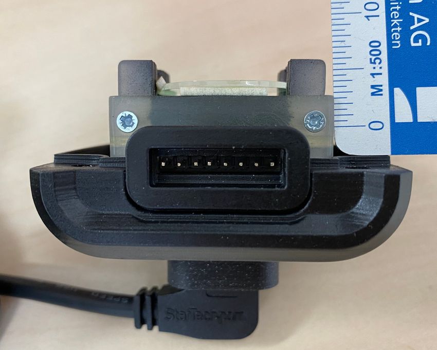
well as IMU data at 200Hz. Timestamps between all sensors are (a) left visual frame (b) right visual frame
synchronized in hardware. The event cameras contain a large
sensor of 1280x720 pixels, which is significantly larger than
the sensors used in existing stereo event datasets. We provide
ground truth poses from a motion capture system at 120Hz
during the beginning and end of each sequence, which can be
used for trajectory evaluation. TUM-VIE includes challenging
sequences where state-of-the art visual SLAM algorithms either
fail or result in large drift. Hence, our dataset can help to push
the boundary of future research on event-based visual-inertial
perception algorithms. (c) left event frame (d) right event frame
Fig. 1: This scene is captured in low-light conditions outside.
I. INTRODUCTION
It demonstrates the high dynamic range advantage of the
Event cameras, also known as dynamic vision sensors event camera (bottom row) compared to the visual camera
(DVS), are passive imaging sensors, which report changes (top row). It shows all four camera modalities of the sequence
in the observed logarithmic brightness independently per bike-dark at 83.6 seconds recording time. Note that later
pixel. Their main benefits are very high dynamic range in this sequence there is more ambient light present and
(up to 140dB compared to 60dB of traditional cameras), hence the visual frames can still be used in computer vision
high temporal resolution and low latency (in the order of algorithms. For this visualization, the asynchronous events
microseconds), low power consumption and strongly reduced are accumulated into frames using an integration time of 5
motion blur [1, 2]. Hence, these novel sensors have the milliseconds.
potential to revolutionize robotic perception. Figure 1 shows
the superior performance of an event camera in low light
conditions.
Due to the novelty of the field, algorithms for event- More importantly, it enables the evaluation of frame-based
based sensors are still immature compared to frame-based versus event-based algorithms on data with similar, state-
algorithms. Computer vision research in the last fifty years of-the-art resolution. To facilitate this, our setup contains
has strongly profited from publicly available datasets and two hardware-synchronized global shutter cameras of reso-
benchmarks. To advance research with these novel and lution 1024x1024 pixels, 12 bit color depth, known exposure
expensive sensors, we introduce the TUM-VIE dataset. It times and vignette calibration. The IMU provides 3-axis
contains a variety of sequences captured by a calibrated and accelerometer and gyroscope data at 200 Hz. Contrary to
hardware-synchronized stereo pair of Prophesee GEN4 CD most existing datasets, we provide the calibration of IMU
sensors with 1280x720 pixels resolution. To our knowledge, biases, as well as axis scaling and misalignment similar
TUM-VIE is the first stereo dataset featuring such a high- to [3]. The timestamps of all sensors are synchronized in
resolution event camera, surpassing other datasets by at least hardware.
a factor of ten in the number of event pixels per camera. TUM-VIE can for example be used to develop algorithms
In principle, this allows for more detailed reconstructions. for localization and mapping (visual odometry and SLAM),
feature detection and tracking, 3D reconstruction, as well as
∗ These authors contributed equally. The authors are with the Computer
self-supervised learning and sensor fusion. The availability
Vision Group, Department of Informatics, Technical University of Munich,
Germany. {simon.klenk, jason.chui, nikolaus.demmel, of comprehensive datasets combining comparable sensor
cremers}@tum.de. modalities to TUM-VIE is quite small. Furthermore, sensor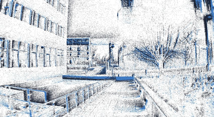
characteristics of event camera have greatly improved within
the last decade [1]. Hence, we believe it is important to use
the most recent event camera for a meaningful comparison
with frame-based algorithms.
   The main contributions of this paper are:
   • We present the first 1 megapixel stereo event dataset
     featuring IMU data at 200Hz and stereo global shutter
     grayscale frames at 20Hz with known photometric cali-
     bration and known exposure times. Timestamps between
     all sensors are hardware-synchronized.
   • The first stereo event dataset featuring head mounted
     sequences (relevant for VR) and sport activities with
     rapid and high-speed motions (biking, running, sliding,
     skateboarding).
   • We propose a new method for event camera calibration
     using Time Surfaces.
   • We evaluate our dataset with state-of-the-art visual
     odometry algorithms. Furthermore, we make all cali-
     bration sequences publicly available.
The dataset can be found at:
              https://go.vision.in.tum.de/tumvie                  Fig. 2: Sensor setup mounted onto a helmet. The distance
                                                                  between event camera (bottom) and visual camera (top) is
                    II. R ELATED W ORK                            only 4.49 centimeters for the left and right side of the
   Weikersdorfer et al. [4] present one of the earlier event      stereo rig. The baseline between the visual cameras is 10.86
datasets, combining data from an eDVS of 128x128 pixels           centimeters, the baseline between the event cameras is 11.84
and an RGB-D sensor in a small number of indoor sequences.        centimeters. These numbers are obtained from our calibration
They provide ground truth poses from a motion capture             algorithm and confirmed by physical measurements.
(MoCap) system, but the total sequence length only amounts
to 14 minutes.
   Barrancko et al. [5] provide a dataset which focuses on        and two-wheeler. They provide RGB images recorded at 4
evaluation of visual navigation tasks. They use a dynamic         megapixels as well as an event stream recorded by the 1
and active pixel vision sensor (DAVIS) which combines event       megapixel Prophesee GEN4-CD sensor, which is also used
detection alongside regular frame-based pixels in the same        in this work.
sensor. However, only 5 degree-of-freedom (DOF) motions              Furthermore, there exit specialised datasets such as the
are captured and the ground truth poses are acquired from         UZH-FPV Drone Racing Dataset [10], which is targeted for
wheel odometry which is subject to drift.                         localization of drones during high speed and high accelera-
   The work by Mueggler et al. [6] captures full 6 DOF            tions in 6 DOF. The sensor setup includes a miniDAVIS346
motions and precise ground truth by a MoCap system                as well as a fisheye stereo camera with 640x480 pixels reso-
indoors. The sequences include artificial scenes such as          lution and hardware-synchronized IMU. In addition, external
geometric shapes, posters or cart boxes, but also an urban        ground truth poses of the drone are provided by a laser
environment and an office. Hardware-synchronized grayscale        tracker system at 20Hz. However, partial tracking failures
frames and IMU measurements are provided in addition to           during high-acceleration maneuvers are reported. Lee et al.
the events. They also present an event camera simulator in        [11] present the dataset ViViD, which contains sequences for
their work. However, the monocular DAVIS 240C merely              visual navigation in poor illumination conditions. In addition
captures 240x180 pixels and the total sequence length only        to lidar and RGB-D data, they record thermal images with a
amounts to 20 minutes.                                            resolution of 640x512 pixels at 20Hz. They provide ground
   There also exits a small number of related datasets tar-       truth poses from a MoCap system indoors and use a state-of-
geting automated driving applications. Binas et al. present       the-art lidar SLAM system for outdoor ground truth poses.
DDD17 [7] as well as the follow-up dataset DDD20 [8]              However, the monocular DAVIS stream features only a
which feature monocular event data from a DAVIS 346B with         resolution of 240x180 pixels and the timestamps between
346x260 pixels. The camera is mounted on a car windshield         the sensors are not synchronized in hardware.
while driving through various environments and conditions,           The dataset MVSEC by Zhu et al. [12] as well as the recent
for a total of 12 and 51 hours, respectively. Additionally, GPS   dataset DSEC by Gehrig et al. [13] are most closely related
data and vehicle diagnostic data such as steering angle and       to our work. Both MVSEC and DSEC contain a lidar sensor
vehicle speed are provided. Similarly, the dataset by Perot et    for depth estimation, two frame cameras, two event cameras
al. [9] comprises 14 hours of recording from a car. It includes   as well as a GNSS receiver. DSEC addresses the limitation
labelled bounding boxes for the classes of car, pedestrian        of a small camera baseline in MVSEC targeting automated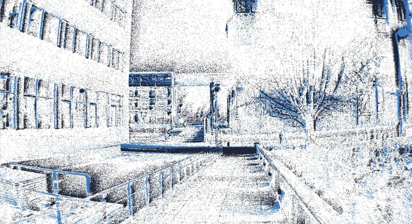
driving scenarios. TUM-VIE comes with a number of com-                            TABLE I: Hardware Specification
plementary advantages. First, our event camera provides 10
                                                                              Sensor                   Rate             Properties
times more pixels than the DAVIS m346B in MVSEC and                                                                  1280x720 pixels
3 times more pixels than the Prophesee Gen3.1 in DSEC.               2x Prophesee GEN4-CD
                                                                                                  ≤   109 events
                                                                                                            s
                                                                                                                   FOV: 90◦ H / 65◦ V
                                                                        lens: Foctek M12-5IR
This can help to study the impact of high resolution data                                                             up to 124 dB
                                                                                                                    1024x1024 pixels
on algorithmic performance and in principle allows a more              2x IDS Camera uEye
                                                                                                                   FOV: 101◦ H / 76◦ V
detailed reconstruction. Second, our visual stereo cameras              UI-3241LE-M-GL                20 Hz
                                                                                                                       up to 60 dB
                                                                     lens: Lensagon BM4018S118
encompass a largely increased field of view compared to the                                                           global shutter
                                                                                                                    3D accelerometer
VI sensors in MVSEC. Third, in contrast to both MVSEC                  IMU Bosch BMI160                               3D gyroscope
and DSEC, we provide a photometric calibration for our                                                200 Hz
                                                                      integrated on Genuino 101                        up to 60 dB
visual cameras, which is beneficial for employing direct VO                                                            temperature
methods on the intensity images [14]. Fourth, we provide                                                            accurate 6D pose
                                                                     MoCap OptiTrack Flex13           120 Hz
                                                                                                                     850nm IR light
calibrated IMU noise parameters which are required for
accurate probabilistic modeling in state estimation algorithms
[3]. The MVSEC dataset features sequences on a hexacopter,
on a car at low speed (12 m/s), and on a motorcycle at high
speed (12-36 m/s) totalling about 60 minutes. However, only
about 6 minutes of handheld indoor recordings are provided.
Similarly, the DSEC dataset contains 53 minutes of outdoor
driving on urban and rural streets. Contrary to that, the TUM-
VIE dataset provides extensive handheld and head-mounted
sequences during walking, running and sports in indoor and
outdoor scenarios and under various illumination conditions,
totalling 48 minutes excluding the calibration sequences.

                        III. DATASET
                                                                  Fig. 3: The infrared filter is mounted parallel to the sensor, at
A. Sensor Setup                                                   a distance of approximately 2 millimeter. The sensor plane is
   Table I gives an overview of our sensors and their char-       located approximately at the 5 millimeter mark of the ruler.
acteristics. The full setup including the attached infrared
markers can be seen in Figure 2. We use the Prophesee
GEN4-CD Evaluation Kit which includes a 1 megapixel               sequences called calib-vignette, which are used to compute
event sensor in a robust casing and a USB 3.0 interface.          the photometric calibration of the visual cameras.
The Prophesee GEN4 CD sensor can handle a peak rate of               The first seven sequences in Table II with prefix mocap
1 Giga-event per second. In most sequences we have a mean         contain ground truth poses for the whole trajectory: mocap-
event rate of a few Mega-events per second.                       1d-trans contains a simple one dimensional translational
   The MoCap system emits 850nm infrared (IR) light in            motion, mocap-3d-trans contains a three dimensional trans-
order to track the IR-reflective passive markers which are        lation and mocap-6dof contains a full 6 DOF motion. All
attached to the rigid body setup. Since the Prophesee GEN4        three sequences show a table containing diverse objects such
CD sensor is sensitive to IR light, moving the setup inside the   as books, multiple similarly looking toy figures and cables.
MoCap room would create undesirable noise events. There-          Most of the the scene is bounded by a calibration pattern
fore, we place an IR-blocking filter with cutoff frequency of     placed behind the table. The sequences mocap-desk and
710nm parallel to the sensor, at a distance of approximately      mocap-desk2 show a loop motion around two different office
2 millimeter, see Figure 3. The placement close to the sensor     desks: mocap-desk shows two computer screens, a keyboard
has the benefit that stray light inside the camera is also        with some cables and the scene is bounded by a close-by
blocked.                                                          white wall; mocap-desk2 also shows two screens but the
                                                                  depth is less strictly bounded and there are also multiple
B. Sequence Description                                           calibration patterns and desk accessories visible.
   Table II gives an overview of the available sequences.            The sequence office-maze is recorded during a walk
Total recording length amounts to 48 minutes excluding            through various offices and hallways in the university build-
the calibration sequences. For each day of recording, we          ing. The sequence running-easy is recorded in handheld
provide a sequence called calib which is used to calibrate        mode while running through the corridor of the office. In
the extrinsic and intrinsic parameters of all cameras. The        the sequence running-hard, the camera is rapidly rotated
sequence called imu-calib is used to obtain the transforma-       during running such that it faces the office wall for short
tion between the marker coordinate system (infrared markers       moments. This makes it hard to perform camera tracking.
for MoCap) and the IMU, as well as to determine the IMU           However, the wall features research posters such that there
biases and scaling factors. Furthermore, we provide two           is still texture present for tracking.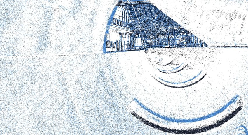
TABLE II: Sequence Overview

           Sequence      Duration(s)   MER(106 events/s)
        mocap-1d-trans      36.6             14.8
        mocap-3d-trans      33.2             24.9
          mocap-6dof        19.5            27.15
          mocap-desk        37.5             29.7
         mocap-desk2        21.4             28.4
         mocap-shake        26.3            26.55
        mocap-shake2        26.7             22.3
          office-maze       160               28
         running-easy        73             27.25                     (a) left visual frame           (b) right visual frame
         running-hard        72              26.2
           skate-easy        79             26.25
           skate-hard        86              25.7
          loop-floor0       284             29.55
          loop-floor1       257             29.55
          loop-floor2       240              28.3
          loop-floor3       256              29.7
          floor2-dark       152             17.45                     (c) left event frame            (d) right event frame
              slide         196               28
           bike-easy        288              26.8                Fig. 4: run-easy sequence at 25.1 seconds. The visual
           bike-hard        281              26.9                frames contain significant motion blur on the poster and
           bike-dark        261             25.35                oversaturation in the middle part of the image, whereas the
                                                                 event frames can capture many details.

   The sequence skate-easy traverses the same corridor as
running-easy and running-hard with a skateboard. In skate-
hard, the camera is rapidly rotated to face the wall for a few
seconds during the ride.
   The sequence loop-floor0 to loop-floor3 are obtained by
walking through the university building on the respective
floor. These four datasets can be used to test loop closure
detection algorithms in the event stream, which is still an
immature research field. We additionally provide the se-
quence floor2-dark. This sequence shows the high dynamic              (a) left visual frame           (b) right visual frame
range advantage of the event camera over the visual camera.
We believe that with better event-based SLAM algorithms,
the path could be tracked accurately even in this low-light
condition, whereas state-of-the art visual SLAM systems fail,
see Table IV.
   The sequence slide shows a path through the university
building while sliding from floor3 to floor0 in the middle
of the sequence. This sequence contains high dynamic range            (c) left event frame            (d) right event frame
and high speed motion.                                           Fig. 5: slide sequence at 93.7 seconds. Due ot the auto-
   The bike sequences are recorded with the helmet worn          exposure algorithm in the visual cameras, the exposure
on the head, whereas all other sequences are recorded in         adapts quickly and details in the bright background are
handheld mode. bike-easy contains a biking sequence during       visible. However, a few frames earlier in this sequence, the
the day at medium speed. bike-hard traverses the same path       frames are similarly oversatured as in Figure 4.
as bike-easy, additionally containing rapid rotations of the
sensor setup, suddenly facing sideways or down on the road.
bike-dark contains a slightly shorter path than the other bike                         IV. C ALIBRATION
sequences, recorded at night in low-light conditions outside.
   In Figure 1, 4 and 5 we show both visual frames and           A. Intrinsic and Extrinsic Camera Calibration
events of a few selected sequences. The events are visualized       The field of view among all cameras is only partially over-
as accumulated frames with an accumulation time of 5             lapping. Hence, to allow for extrinsic calibration between our
milliseconds. Positive events are visualized in blue, negative   camera modalities we use a pattern of AprilTags [15]. This
events in black and white color is used to indicate no change.   pattern allows to perform robust data association between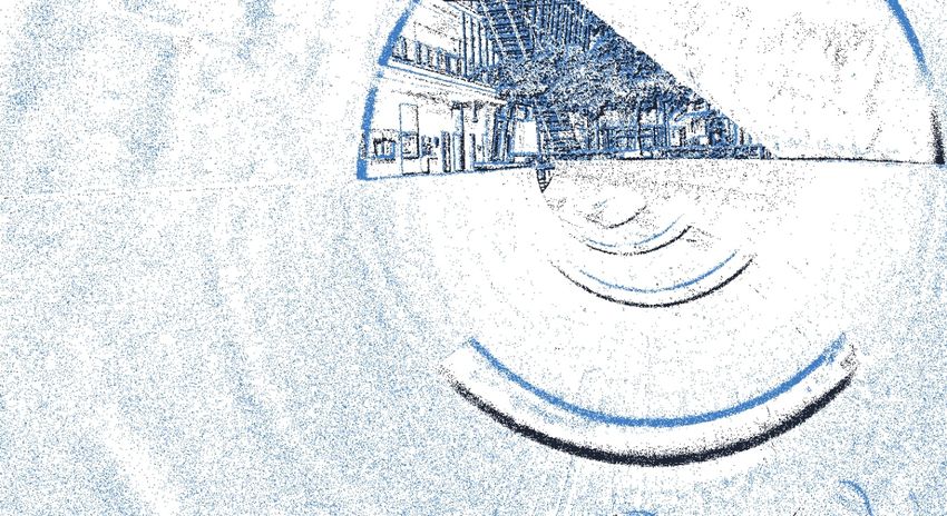
is created as follow,
                                                                                                  1
                                                                                Tttarget [x, y] = (e−α|tlast −ttarget | + e−α|tnext −ttarget | )
                                                                                                  2
                                                                                                                                               (2)
                                                                             where tlast is the timestamp of the previous event at pixel
                                                                             [x, y] before ttarget , tnext is the timestamp of next event at
                                                                             pixel [x, y] after ttarget and α is the decay rate. Using a time
                                                                             surface representation, we noticed a higher detection recall of
                                                                             AprilTags and hence a slightly more robust calibration. To
                                                                             perform this joint calibration, we modified the calibration
Fig. 6: The April-grid pattern has been reconstructed based                  tools from Basalt [17]. A time surface created with the
on creating the time surface. Using time surfaces showed                     described method can be seen in Figure 6. We provide
slightly better AprilTag detection recall compared to accu-                  the calibration parameters as well as the raw calibration
mulated event frames.                                                        sequences for each day of recording.
                                                                             B. IMU intriniscs, IMU-Camera-extrinsics
                                                                                Similar to the TUM-VI dataset [3], we assume that the
recognized tags from different cameras. It is displayed by a                 IMU measurements are subject to white noise with standard
commodity computer screen, blinking at a fixed frequency.                    deviation σw and an additive bias value. The bias value is
We move the multi-camera setup around the screen to capture                  changing according to a random walk over time. The random
the pattern from various poses.                                              walk is modelled as integration of white noise with standard
                                                                             deviation σb . To determine the parameter σw , a slope of − 12
   The intrinsic and extrinsic parameters for both visual and
                                                                             is fitted to the range of 0.02 ≤ τ ≤ 1 in the log-log plot of
event cameras are determined in a joint optimization. To al-
                                                                             the Allan deviation. To determine the bias parameter σb , a
low for accurate intrinsic parameter estimation, in particular
                                                                             slope of 21 is fitted to the range 1000 ≤ τ ≤ 6000 seconds.
radial distortion of the lenses, we validate for each calibration
                                                                             The values for σw and σb can then be taken as the y-value
sequence that the detections of AprilTags are spread over the
                                                                             of the fitted line at τ = 1 and τ = 3, respectively. This
full image dimension of each camera.
                                                                             procedure is visualized in Figure 7 and 8.
   To enable detection of AprilTags in the event stream, we                     The extrinsic calibration between IMU and visual cameras
transform the events into a frame-like structure. One popular                is obtained by using a static Aprilgrid pattern. Calibration
method is to accumulate events within a certain time interval                data is found in imu-calib. All six degrees of freedom are
t ∈ [ttarget −∆t, ttarget +∆t] into frames. However, in order                excited during this calibration while the pattern is constantly
to create sharper event frames at time ttarget , we use the                  in the field of view of the visual cameras. The exposure time
time surface representation instead. Inspired by [16], we use                is set to a low value of 3.2 milliseconds to minimize motion
time surfaces which take the latest as well as the next future               blur but still allow detection of AprilTags. We leave the
event at time ttarget into account. The time-surface Tttarget                extrinsic between the visual cameras fixed and only optimize
                                                                             the transformation between IMU and visual camera frame.
                                                                               normal Allan deviation [rad/s]
  normal Allan deviation [m/s2]

                                  10−1              acc x       slope -1/2                                                       gyro x       slope -1/2
                                                                                                                10−3
                                                    acc y       slope 1/2                                                        gyro y       slope 1/2
                                                    acc z                                                                        gyro z
                                  10−2
                                                                                                                10−4
                                                                                                                                 σw
                                  10−3
                                                   σw

                                                                                                                10−5
                                  10−4
                                                        σb
                                                                                                                                      σb
                                       −5                                                                            −6
                                  10                                                                            10
                                            10−1         101    103                                                       10−1         101    103
                                                        τ [s]                                                                         τ [s]

Fig. 7: Accelerometer log-log plot of Allan deviation over                   Fig. 8: Gyroscope log-log plot of Allan deviation over inte-
integration time τ . We obtain the IMU noise values of                       gration time τ . We obtain the IMU noise values of σw,gyro =
σw,acc = 0.0012 at τ = 1 and σb,acc = 2.2856 x 10⁻⁵ at                       8.4503 x 10⁻⁵ at τ = 1 and σb,gyro = 1.1961 x 10⁻⁶ at
τ = 3.                                                                       τ = 3.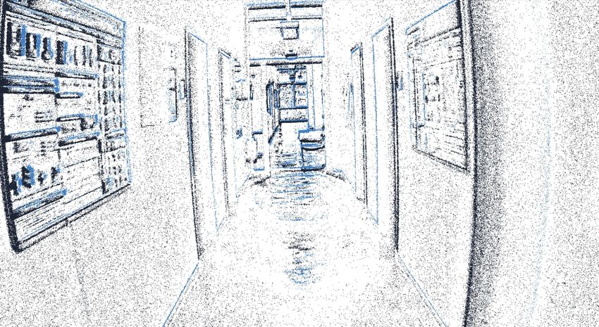
Fig. 10: Alignment of angular velocities between gyroscope
Fig. 9: Coordinate systems which we have used in this paper.
                                                                measurements and Mocap estimations (using central differ-
Solid lines are the relative poses found during calibration,
                                                                ences of poses). The obtained time offset ∆tgt,m between
dashed lines are the relative poses measured in real-time.
                                                                MoCap clock and IMU clock is provided for each sequence.
Colors indicate the respective raw sensor clock before tem-
poral calibration.
                                                                puter, a rough estimate of this offset is obtained from the
                                                                system’s recording time. A refinement of this estimate is
C. Temporal Calibration
                                                                obtained by aligning angular velocities measured by the IMU
   All sensors on the setup are synchronized in hardware.       with estimated angular velocities which are obtained from
An overview of the different sensor clocks can be seen          central differences between MoCap poses, as can be seen
in Figure 9. We report all timestamps in the left event         in Figure 10. The offset ∆tgt,m which minimizes the sum
camera’s clock (main clock). The synchronization between        of all squared errors is estimated for each sequence. For
left and right event camera is achieved through the available   the trajectories where we exit and later re-enter the MoCap
synchronization connections of the Evaluation Kit.              room, we compute this offset once for the beginning and
   The Genuino 101 triggers the visual cameras, measures        once for the end of the sequence to account for clock drift.
exposure start and stop timestamps and reads the IMU values.    The provided ground truth poses in the dataset have corrected
As mentioned above, we define the timestamp of an image         timestamps and are reported in the main clock. Additionally,
as mid-exposure point. Hence, timestamps of the images          we provide the estimated offsets to facilitate custom time-
are well-aligned with IMU measurements in Genuino clock.        alignment approaches.
However, due to the IMU readout delay, there exits a constant
                                                                D. Biases and Event Statistics
offset of 4.77 milliseconds. We determine this offset exactly
once during calibration and correct it in all recordings.          Table III shows the biases of the event cameras, which are
   To transform IMU and image timestamps from Genuino           the same in all sequences. The ratio of ON over OFF pixels
clock to main clock, we additionally measure exposure start     is approximately 0.7 in all sequences and for both cameras.
and stop timestamps via trigger signal in the left event             V. E VALUATION OF STEREO -VIO A LGORITHMS
camera. Data association between triggers on the Genuino
and triggers on the event camera is achieved through a            To verify the data and calibration quality, we test all
distinctive startup sequence, which alternates extremely high   sequences with state-of-the-art open-source visual-inertial
and low exposure times. We notice a linear relation between     odometry systems. We provide evaluation for Basalt [17] and
Genuino and main clock, i.e. there exists a constant offset     VINS-Fusion [18, 19, 20]. The methods are used with default
b and a small constant clock drift m between both clocks.
Whereas the value of b is different for each sequence, the          TABLE III: Biases of Prophesee GEN4-CD sensor
value of m is usually around 2 milliseconds per minute
(Genuino clock runs faster than main clock). We obtain the                             bias name      value
linear coefficients from a least-squares fit and correct for                            bias diff       69
                                                                                      bias diff off     52
them in each sequence, such that all sensor data is provided                          bias diff on     112
in main clock.                                                                         bias fo n        23
   Ground truth poses are recorded in MoCap clock. We                                   bias hpf        48
                                                                                         bias pr       151
model a constant offset ∆tgt,m between MoCap clock and                                  bias refr       45
main clock. Since all data is recorded on the same com-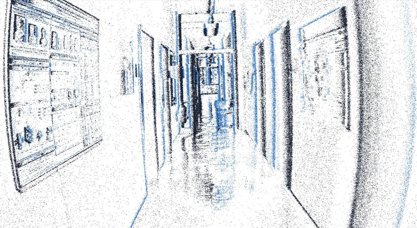
parameters on full resolution images (1024 x 1024 pixels).
     TABLE IV: Absolute trajectory errors (ATE) [m]              The results are summarised in Table IV and a visualization
                                                                 for some sequences is showed in Figure 11. An x in Table
          Sequence      Basalt   VINS-Fusion   length[m]
                                                                 IV indicates an ATE larger than the sequence’s path length
       mocap-1d-trans   0.003       0.011         5.01
       mocap-3d-trans   0.009       0.010         6.85           or that the method fails. Basalt and VINS-Fusion perform
         mocap-6dof     0.014       0.017         5.30           well for non-challenging sequences as expected.
         mocap-desk     0.016       0.058         9.44              However, our evaluation also shows that Basalt and VINS-
        mocap-desk2     0.011       0.013         5.34
        mocap-shake        x           x          24.5           Fusion result in large drift for most of the challenging
       mocap-shake2        x          x           26.2           sequences, e.g. with fast motion in running-easy, running-
         office-maze     0.64        4.40         205            hard, skate-hard, slide, and bike-hard or with low light,
        running-easy     1.34        0.78         113
        running-hard     1.03        1.74         117            e.g. in floor2-dark and bike-dark. This means that the
          skate-easy     0.22        1.74         114            dataset is challenging enough for state-of-the-art visual-
          skate-hard     1.78        0.97         113            inertial systems and can be used for further research in event-
         loop-floor0     0.58       3.43          358
         loop-floor1     0.66       1.72          338            based visual-inertial odometry algorithms.
         loop-floor2     0.48       2.04          282
         loop-floor3     0.51       8.36          328
                                                                                         VI. C ONCLUSION
         floor2-dark     4.54        4.54         254               In this paper, we propose a novel dataset with a diverse
             slide       1.54        2.44         248
          bike-easy      1.62       13.10         788
                                                                 set of sequences, including small and large-scale scenes. We
          bike-hard      2.01        9.88         784            specifically provide challenging sequences in low light and
          bike-dark      6.26       20.20         670            high dynamic-range conditions as well as during fast motion.
                                                                 Our dataset composes of a high-resolution event stream and
                                                                 images captured by a wide field of view lens, as well as IMU
                                                                 data and partial ground truth poses.
                                                                    We evaluate our dataset with state-of-the-art visual-
                                                                 camera-based stereo-VIO. The results show that there are
                                                                 open challenges which need new algorithms and new sensors
                                                                 to tackle them. Event-based odometry algorithms are still
                                                                 immature compared to frame-based methods, which makes
                                                                 it difficult to present an evaluation of event-based algorithms.
                                                                 Hence, our dataset can be useful for further research in the
         (a) floor 0                     (b) mocap 6dof          development of event-based visual-inertial odometry, as well
                                                                 as 3D reconstruction and sensor fusion algorithms.
                                                                                  ACKNOWLEDGMENT
                                                                    We thank everybody who contributed to the paper. In
                                                                 particular, we want to thank Mathias Gehrig (University of
                                                                 Zurich) for supporting us with the h5 file format. We also
                                                                 thank Lukas Koestler (Technical University of Munich) for
                                                                 helpful suggestions and proofreading the paper. Additionally,
         (c) shake 2                     (d) floor 2 night       we thank Yi Zhou (HKUST Robotics Institute) for his helpful
                                                                 comments. This work was supported by the ERC Advanced
                                                                 Grant SIMULACRON.
                                                                                         R EFERENCES
                                                                  [1]   Guillermo Gallego, T. Delbrück, G. Orchard, C. Bar-
                                                                        tolozzi, B. Taba, A. Censi, Stefan Leutenegger, A.
                                                                        Davison, J. Conradt, Kostas Daniilidis, and D. Scara-
                                                                        muzza. “Event-based Vision: A Survey”. In: IEEE
         (e) shake 1                      (f) bike night                transactions on pattern analysis and machine intel-
                                                                        ligence PP (2020).
Fig. 11: Results of evaluated methods for 2 easy sequences        [2]   Tobi Delbruck, Yuhuang Hu, and Zhe He. V2E: From
(a, b) and 4 challenging sequences (c, d, e, f) from our                video frames to realistic DVS event camera streams.
dataset. The ground truth is shown in black for the segments            2020. arXiv: 2006.07722.
of the trajectory where it is available. The presented results    [3]   D. Schubert, T. Goll, N. Demmel, V. Usenko, J.
are obtained with default parameters. Noise parameters are              Stueckler, and D. Cremers. “The TUM VI Benchmark
set to inflated values from the Allan plots in Figure 7 and 8           for Evaluating Visual-Inertial Odometry”. In: Interna-
to account for unmodeled noise and vibrations.                          tional Conference on Intelligent Robots and Systems
                                                                        (IROS). Oct. 2018.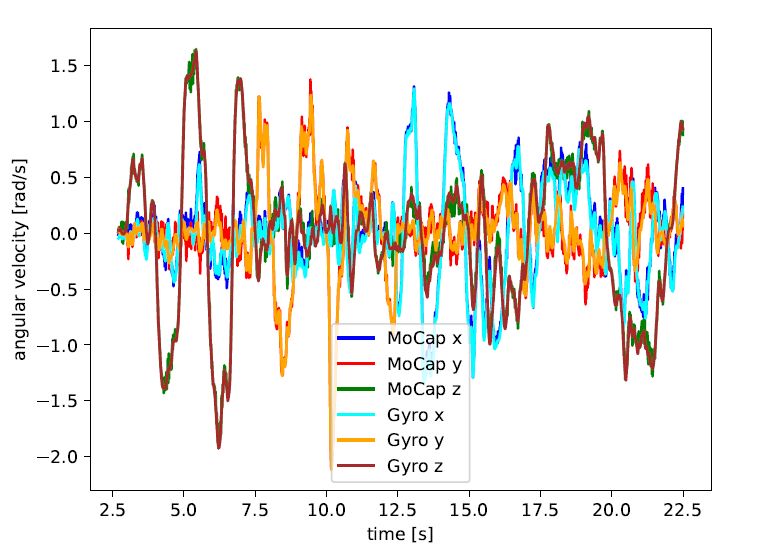
[4]   D. Weikersdorfer, D. B. Adrian, D. Cremers, and                 Dataset Generation and Benchmarking of SLAM Al-
       J. Conradt. “Event-based 3D SLAM with a depth-                  gorithms for Robotics and VR/AR. 2019.
       augmented dynamic vision sensor”. In: 2014 IEEE          [12]   Alex Zihao Zhu, Dinesh Thakur, Tolga Özaslan, Bernd
       International Conference on Robotics and Automation             Pfrommer, Vijay Kumar, and Kostas Daniilidis. “The
       (ICRA). 2014, pp. 359–364.                                      Multi Vehicle Stereo Event Camera Dataset: An Event
 [5]   Francisco Barranco, Cornelia Fermuller, Yiannis Aloi-           Camera Dataset for 3D Perception”. In: IEEE Robotics
       monos, and Tobi Delbruck. “A Dataset for Visual Nav-            and Automation Letters 3 (2018).
       igation with Neuromorphic Methods”. In: Frontiers in     [13]   Mathias Gehrig, Willem Aarents, Daniel Gehrig, and
       Neuroscience 10 (2016), p. 49.                                  Davide Scaramuzza. “DSEC: A Stereo Event Camera
 [6]   Elias Mueggler, Henri Rebecq, Guillermo Gallego,                Dataset for Driving Scenarios”. In: IEEE Robotics and
       Tobi Delbruck, and Davide Scaramuzza. “The Event-               Automation Letters (2021).
       Camera Dataset and Simulator: Event-based Data for       [14]   J. Engel, V. Koltun, and D. Cremers. “Direct Sparse
       Pose Estimation, Visual Odometry, and SLAM”. In:                Odometry”. In: IEEE Transactions on Pattern Analysis
       International Journal of Robotics Research, Vol. 36,            and Machine Intelligence (Mar. 2018).
       Issue 2, (Feb. 2017), pp. 142–149.                       [15]   E. Olson. “Apriltag: A robust and flexible visual fidu-
 [7]   Binas Binas, Neil J., Liu D., S.-C., and T. Delbruck.           cial system,” in: 2011 IEEE International Conference
       “DDD17 End-To-End DAVIS Driving Dataset”. In:                   on Robotics and Automation. 2011.
       ICML17 Workshop on Machine Learning for Au-              [16]   Yi Zhou, Guillermo Gallego, and Shaojie Shen. Event-
       tonomous Vehicles. 2017.                                        based Stereo Visual Odometry. 2021. arXiv: 2007.
 [8]   Y. Hu, J. Binas, D. Neil, S.-C. Liu, and T. Delbruck.           15548 [cs.CV].
       “DDD20 End-to-End Event Camera Driving Dataset:          [17]   V. Usenko, N. Demmel, D. Schubert, J. Stueckler,
       Fusing Frames and Events with Deep Learning for                 and D. Cremers. “Visual-Inertial Mapping with Non-
       Improved Steering Prediction”. In: Special session              Linear Factor Recovery”. In: IEEE Robotics and Au-
       Beyond Traditional Sensing for Intelligent Transporta-          tomation Letters (RA-L) Int. Conference on Intelligent
       tion (23rd IEEE International Conference on Intelli-            Robotics and Automation (ICRA) 5.2 (2020), pp. 422–
       gent Transportation Systems). Sept. 2020.                       429.
 [9]   E. Perot, P. de Tournemire, D. Nitti, J. Masci, and      [18]   Tong Qin, Peiliang Li, and Shaojie Shen. “VINS-
       A. Sironi. “Learning to Detect Objects with a 1                 Mono: A Robust and Versatile Monocular Visual-
       Megapixel Event Camera”. In: Advances in Neural                 Inertial State Estimator”. In: IEEE Transactions on
       Information Processing Systems 33 (NeurIPS). 2020.              Robotics 34.4 (2018), pp. 1004–1020.
[10]   Jeffrey Delmerico, Titus Cieslewski, Henri Rebecq,       [19]   Tong Qin, Jie Pan, Shaozu Cao, and Shaojie Shen.
       Matthias Faessler, and Davide Scaramuzza. “Are We               A General Optimization-based Framework for Local
       Ready for Autonomous Drone Racing? The UZH-FPV                  Odometry Estimation with Multiple Sensors. 2019.
       Drone Racing Dataset”. In: IEEE Int. Conf. Robot.               eprint: arXiv:1901.03638.
       Autom. (ICRA). 2019.                                     [20]   Tong Qin, Shaozu Cao, Jie Pan, and Shaojie Shen.
[11]   A Lee, Cho J., Yoon Y., S. Shin, and A Y. Kim.                  A General Optimization-based Framework for Global
       “ViViD: Vision for Visibility Dataset”. In: IEEE Int.           Pose Estimation with Multiple Sensors. 2019. eprint:
       Conf. Robotics and Automation (ICRA) Workshop:                  arXiv:1901.03642.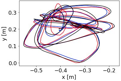
You can also read