CONTROL SYSTEM GUIDE 2018-2019 FTC - More Than Robots - FIRST Tech Challenge UK
←
→
Page content transcription
If your browser does not render page correctly, please read the page content below
2018-2019 FTC
             CONTROL SYSTEM GUIDE

ftc-uk.org                          More Than Robots™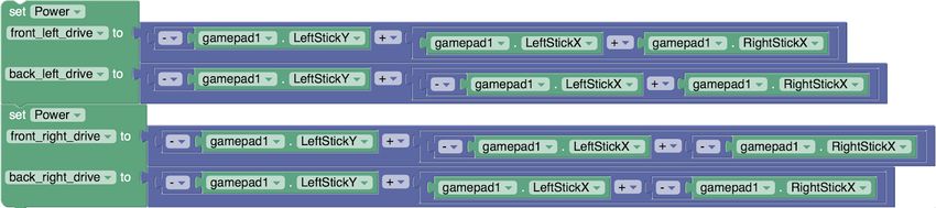
TABLE OF CONTENTS

About                                                                 1

Control System Hardware                                               2
  FTC Control System Hardware Overview                                2
		       Main Power Switch                                            2
		       Robot Main Battery                                           2
		       Android Device                                               2
		       Control Modules                                              3
		       Motor and Servo Controllers                                  3
		       DC Motors                                                    4
		       Sensors                                                      5
  Wiring the FTC Control System                                       7
  Best Practices for Wiring                                           7
		       Mounting the Android Device                                  7
		       Wire Management and Strain Relief                            8
		       Documentation                                                8
		       Labelling                                                    8
		       Re-Check Early and Often                                     8
		       Check Logs                                                   8
  Status Light Quick Reference                                        8
		       REV
                                                                      9
Control System Software                                               9
  FTC Control System Software Overview                                9
		       Android Applications                                         9
         Configuring the Android Device                               9
		       Installing the FIRST® Tech Challenge Applications            9
		       FTC Robot Controller Overview                                10
		       FTC Driver Station Overview                                  11
		       FTC Robot Controller and FTC Driver Station Best Practices
                                                                      12
FTC Blocks Programming                                                12
		      Accessing the Robot Controller Console                        12
		      Creating a Benchtop Test Programme                            12
		      FTC Blocks References                                         13
		      Using Actuators                                               14
        Driving a Robot Using Differential Drive                      15
		      Driving a Robot Using Mecanum Drive                           15
		      Controlling Servos                                            15
        On/Off Control of Motors

ftc-uk.org                                                                 More Than Robots™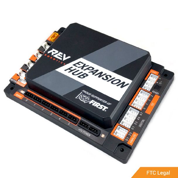
Using Sensors                        16
		           Encoder                              17
		           REV Robotics Colour Sensor           18
		           REV Robotics Potentiometer           18
		           REV Robotics Touch Sensor            19
		           REV Robotics Magnetic Limit Switch   19
		           REV Robotics 2m Distance Sensor      19
		           Driver Station Inputs and Outputs    20
		           Telemetry                            20

Miscellaneous                                     22
		       Communicating with other Team Members    22
		       Control Award                            22

ftc-uk.org                                             More Than Robots™
About

    One goal of FIRST® is to recognise the engineering design process and the journey that
    a team makes: the phases of problem definition, concept design, system-level design,
    detailed design, test and verification, and production of the robot.

    The 2018-2019 FIRST® Tech Challenge Control System guide compiles various FTC®
    resources into one document and serves as a starting point for anyone who wants to
    learn more about the control system. It is specifically tailored to rookie teams in the UK
    and Ireland, as the hardware components mentioned in this guide are the ones in their
    kit of parts; however, other rookie teams should find the guide equally useful.

    The guide is broken up into three parts: Control System Hardware, Control System
    Software, and FTC Blocks Programming. It is vital that the programming section is only
    approached once the content in the first two sections is understood.

    The Editor

    Kaito Arai is a senior (upper sixth) student at the American School in London, where
    he has respectively competed in the FIRST® Lego League (FLL) and FIRST® Robotics
    Challenge (FRC) for two and three years. In both programmes, he has taken major
    programming duties, making him knowledgeable about FIRST® control systems. His
    experience teaching about FIRST® control systems comes from mentoring FLL teams
    and educating his FRC team members on programming.

1

    ftc-uk.org                                                                      More Than Robots™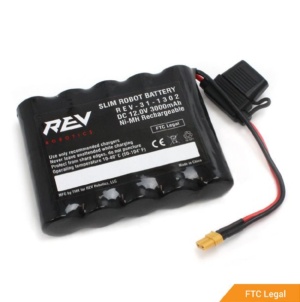
CONTROL SYSTEM HARDWARE

FTC Control System Hardware Overview

Main Power Switch

   REV Robotics Switch Cable and Bracket
   The Robot Main Power Switch must control
   all power provided by the Robot main battery
   pack. This is the safest method for Teams and
   Field personnel to shut down a Robot.

   Add this switch between the battery and
   Expansion Hub to have on/off control of the
   robot. Mount the switch slightly recessed
   from the outside of the robot so that it is not
   accidentally turned off by another robot during
   a match.

Robot Main Battery

   REV Robotics 12V Slim Battery
   All Robot power is provided by a single 12V
   Robot main battery.

   This 10-cell, 12V 3000mAh battery has a low-
   profile configuration to make it easier to mount
   on a robot. The Slim Battery pack is wired with
   an XT30 male connector and an inline 20A
   replaceable ATC fuse.

Android Device

   Motorola Moto G (2nd Generation)

   A FIRST® Tech Challenge Robot is controlled
   by an Android-based platform powered by
   Snapdragon processors. Teams will use two
   Android devices to control their Robot. One
   Android device will be mounted directly onto
   the Robot and act as a Robot Controller. The
   other Android device will be connected to a pair
   of gamepads and will act as the Driver Station
                                                                      2

   ftc-uk.org                                         More Than Robots™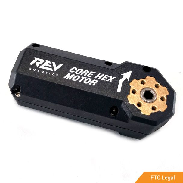
Control Modules
    REV Robotics Expansion Hub

    An integrated electronic device with four (4) DC
    motor channels, six (6) servo channels, eight
    (8) digital I/O channels, four (4) analogue input
    channels, and four (4) independent I2C buses.
    The REV Expansion Hub draws power from an
    approved 12V battery to power these input/
    output channels.

    The REV Expansion Hub is a hardware controller
    which can communicate with any computer,
    including Android tablets/phones and the REV
    Control Hub. The Expansion Hub is loaded with
    hardware interface options to enable driving
    motors and servos, interfacing with sensors, and
    communicating with other devices via several
    protocol options.

    The Hub incorporates ESD and reverse polarity
    protection and is purpose-built to stand up
    to the rigors of use in the classroom or on
    the competition field. In addition to the built-
    in protections, the Hub also features keyed
    and locking connectors to prevent connection
    problems in the heat of competition and is fully

Motor and Servo Controllers
    REV Robotics SPARKmini
    An electronic device that accepts a PWM control
    signal (from a servo controller) and supplies 12V
    power to a DC motor.

    The SPARKmini is an in-line brushed DC
    motor controller designed to offer the same
    performance characteristics as the REV
    Expansion Hub motor ports but in a 60mm x
    22mm footprint.

    SPARKmini responds to the same control signals
    as standard RC servos, so connect it to a free
    servo port and it’s ready to go. Power can be
    connected to a free XT30 port on the Expansion
3

    ftc-uk.org                                          More Than Robots™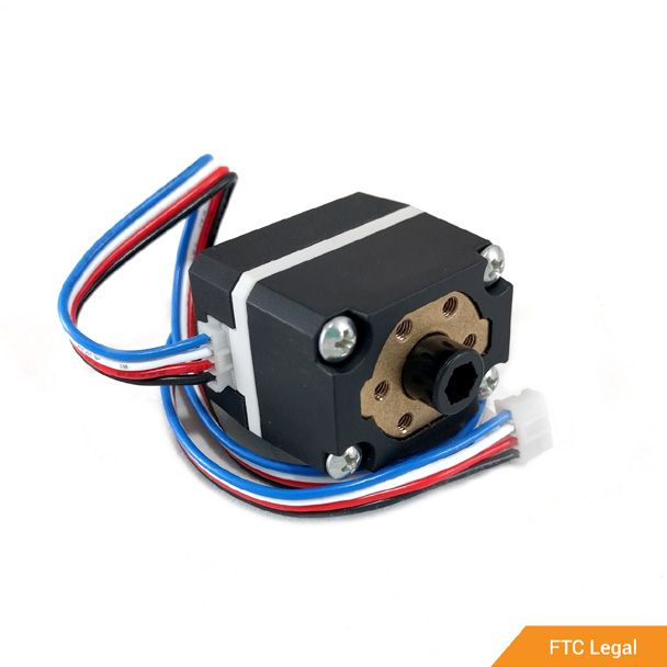
DC Motors

  REV Robotics Core Hex Motor
  The Core Hex Motor is an FTC legal motor that
  features a 90-degree orientation and a female
  output shaft for maximum flexibility and ease
  of use. Insert any of the REV standard 5mm
  hex shafts into or through the Core Hex motor
  to create custom length motor output shafts.
  The Core Hex motor has a built-in magnetic
  quadrature encoder which is compatible with
  5V or 3.3V logic level devices including the
  Expansion Hub.

   REV Robotics HD Hex Motor Version 2

  The HD Hex Motor is an FTC legal motor that
  features a gearbox and an encoder mounted
  to the back side of the motor. 5mm hex
  output shaft makes it easy to connect gears,
  sprockets, wheels, etc. Motor specifications are
  similar in size and power to other FTC motors
  with a more convenient output shaft.

  REV Robotics Smart Robot Servo

  The REV Smart Robot Servo (SRS) is a
  configurable metal-geared servo that takes the
  guesswork out of aligning and adjusting servo-
  based mechanisms. One SRS can be used as
  a standard angular servo, a custom angular
  servo, and a continuous rotation servo by
  simply changing its settings.

                                                                     4

  ftc-uk.org                                         More Than Robots™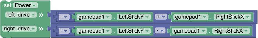
Sensors

    REV Robotics Core Hex Motor
    The Core Hex Motor is an FTC legal motor that
    features a 90-degree orientation and a female
    output shaft for maximum flexibility and ease
    of use. Insert any of the REV standard 5mm
    hex shafts into or through the Core Hex motor
    to create custom length motor output shafts.
    The Core Hex motor has a built-in magnetic
    quadrature encoder which is compatible with
    5V or 3.3V logic level devices including the
    Expansion Hub.

    REV Robotics Potentiometer

    The HD Hex Motor is an FTC legal motor that
    features a gearbox and an encoder mounted
    to the back side of the motor. 5mm hex
    output shaft makes it easy to connect gears,
    sprockets, wheels, etc. Motor specifications are
    similar in size and power to other FTC motors
    with a more convenient output shaft.

    REV Robotics Touch Sensor

    The REV Smart Robot Servo (SRS) is a
    configurable metal-geared servo that takes the
    guesswork out of aligning and adjusting servo-
    based mechanisms. One SRS can be used as
    a standard angular servo, a custom angular
    servo, and a continuous rotation servo by
    simply changing its settings.

5

    ftc-uk.org                                         More Than Robots™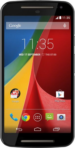
REV Robotics Magnetic Limit Switch

The magnetic limit switch is a three-sided
active-low digital hall effect switch with three
internal hall effect elements located on the top
and sides of the sensor. The three elements are
connected in parallel so that any one of them
will trigger the sensor.

Hall effect sensors detect the presence of
magnetic fields. The magnetic limit switch is an
omni polar momentary switch meaning it will
trigger when there is sufficient field strength of
either magnetic pole (north or south) detected.

REV Robotics 2m Distance Sensor

The 2m distance sensor uses the ST
Microelectronics VL53L0X Time-of-Flight laser-
ranging module to measure distances up to 2
meters with millimetre resolution. Unlike other
ranging sensors that rely on the intensity of
reflected light, this sensor can measure how
long it takes for the light to bounce back, the
“time of flight.” This results in much more
accurate measurements that are independent of
the target’s reflectance.

                                                                     6

ftc-uk.org                                           More Than Robots™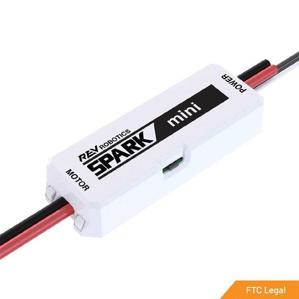
Wiring the FTC Control System

    The diagram above shows how different devices connect to the REV Expansion
    Hub. It is imperative that the devices are connected to the correct type of port,
    otherwise it will not function properly. Pay special attention to the differences
    between the analog, digital, and I2C ports, as they are visually identical. Also, give
    attention to the orientation in which the PWM cable is plugged in: the ground (black)
    wire should be towards the left side on the REV Expansion Hub

Best Practices for Wiring

Mounting the Android Device

    When attaching the Android Phone to the robot, there are many things to keep in
    mind.

    1. It is imperative that the phone is protected from robot-to-robot contact.
    2. The phone should be mounted such that it is not in contact with any metal
       components on the robot. If it is in contact with metal, the phone becomes
       susceptible to electrostatic discharge (ESD).
    3. Similarly, teams should avoid surrounding the phone in metal. If it is mounted at
       the bottom of a robot and surrounded by metal, the metal can interfere with the
       phone’s Wi-Fi connection.
    4. Make sure that the phone is easily accessible for charging, programming, and
       emergencies.
7

    ftc-uk.org                                                                     More Than Robots™
5. Make sure that the phone is mounted such that the camera is available for Vuforia if
desired.
6. Make sure that all wires connected to the phone are securely mounted and are not
in danger of being bumped, damaged, or disconnected. It is essential that there is
no chance of stress being placed on the wire that connects to the phone. If the wire
is stressed, the phone port could be ruined. Wires should be tied down, and there
should be no movement around the port. Phone mounts are available from a variety
of different sources for FIRST® Tech Challenge teams.
Wire Management and Strain Relief
One of the most critical components to robot reliability and maintenance is good
wire management and strain relief. Good wire management is comprised of a few
components:
●● Make sure cables are the correct length. Any excess wire length is just more to
manage. If there is extra wire, secure the extra into a small bundle using separate
cable ties before securing the rest of the wire.
●● Ensure that cables are secured close to connection points, with enough slack
to avoid putting strain on connectors. This is called strain relief and is critical to
minimising the likelihood that a cable comes unplugged or a wire breaks off at a
connection point.
●● Secure cables near any moving components. Make sure that all wire runs are secure
and protected from moving components, even if the moving components were to
bend or over-travel.
●● Secure cables at additional points as necessary to keep wiring neat and clean. Take
care to not over secure wires; if wires are secured in too many locations, it may
actually make troubleshooting and maintenance more difficult.
Documentation
A great way to make maintenance easier is to create documentation describing what
is connected where on the robot. There are a number of ways of creating this type of
documentation which ranges from complete wiring diagrams to excel charts to a quick
list of what functions are attached to which channels. Many teams also integrate these
lists with labelling.
When a wire is accidentally cut, or a mechanism is malfunctioning, or a component
burns out, it will be much easier to repair with documentation of what is connected
where rather than having to trace the wiring all the way through.
Labelling
Labelling is a great way to supplement the wiring documentation described above.
There are many different strategies to labelling wiring and electronics, all with their own
pros and cons. Labels for electronics and flags for wires can be made by hand, using
a label maker, or use different Colours of electrical tape or labelling flags to indicate
8
ftc-uk.org More Than Robots™Re-Check Early and Often
Re-check the entire electrical system as thoroughly as possible after playing the
first match or two (or doing very vigorous testing). The first few impacts the robot
sees may loosen fasteners or expose issues. Create a checklist for re-checking
electrical connections on a regular basis.
Documentation
Take good care of the batteries. A bad battery can easily cause a robot to function
poorly, or not at all, during a match. Label all of the batteries to help keep track of
usage during the event. Many teams also include information such as the age of
the battery on this label.
●● Do not overcharge. Disconnect the battery from the charger once it indicates
a full charge. Typical charge time does not exceed 2 hours. Do not charge a
battery that hasn’t been discharged significantly. For example, running the
robot under minimal load for a few minutes will not significantly discharge the
battery.
●● Discharging the battery past 9.0V can reduce the lifespan of the battery and
can permanently damage the cells. Periodic dips below 9.0V when under load
is expected and OK. For example, don’t forget to unplug the battery when
finished running the robot, and don’t run the robot until it completely stops
responding.
●● Let the battery cool before and after charging. The battery may feel warm after
heavy loading or after charging. This is normal.
Check Logs
After each match, review the logs to see what the battery voltage and current
usage looks like. Once t the normal range of these items is established for the
robot, it can help spot potential issues (bad batteries, failing motors, mechanical
binding) before they become critical failures.
Status Light Quick Reference
REV Robotics Expansion Hub
Re-check the entire electrical system as thoroughly as possible after playing the
first match or two (or doing very vigorous testing). The first few impacts the robot
sees may loosen fasteners or expose issues. Create a checklist for re-checking
electrical connections on a regular basis.
9
ftc-uk.org More Than Robots™LED Description Hub Status
Solid Blue At Expansion Hub has power; Battery is >7V and is
waiting to initialise communications.
Solid Blue Hub is waiting for communication with the Driver
Station Host. Expansion Hub has power; Battery is
>7V.
Solid Green Hub has power and active communication with the
with one or Android Platform. The number of blue blinks is the
more blue same as the Hub’s address.
blinks every ~5
Seconds
Blinking Blue Keep alive has timed out. The fault will clear when
communication resumes.
Blinking Orange Battery Voltage is lower than 7V. Either the 12V
battery needs to be charged, or the Expansion Hub
is running on USB power only. This fault will clear
when the battery voltage is raised above 7V.
This will not be overwritten by the keepalive
timeout pattern.
CONTROL SYSTEM SOFTWARE
Control System Software
Android Applications
Robot Controller Application
The Robot Controller acts as the “brains” of the robot and does all of the thinking
for the robot and tells the robot what to do.
Driver Station Application
The Driver Station allows a team to communicate remotely using a secure and
wireless connection to the Robot Controller and to issue commands to the Robot
Controller.
Robot Controller Console
A programming tool hosted by the Robot Controller.
10
ftc-uk.org More Than Robots™Configuring the Android Device
Checking the Android Version
1. Navigate to Settings > About phone.
2. If the Android version is indicated as 6.0 or higher*, skip to “Naming the
Android Device”. Otherwise, go to “Updating the Android Device”. Repeat
steps for the other device.
* For Motorola Moto G (2nd Generation). For other Android devices, consult
in Game Manual Part 1.
Updating the Android Device
1. Connect to a Wi-Fi network.
2. Navigate to Settings > About Phone and select System Updates. Follow on-
screen instructions to download and install updates.
3. Once updates are complete, refer back to “Checking the Android Version”.
Repeat steps for the other device.
Naming the Android Device
1. For each device, navigate to Settings > Wi-Fi > Advanced > Wi-Fi Direct >
Configure Device.
2. Rename the two devices “[team number]-RC” and “[team number]-DS”,
replacing [team number] with the official team number. Wi-Fi Direct inactivity
timeout should also be set to “Never Disconnect”.
3. Restart the devices to implement changes. Label the devices with their
respective device names to avoid later confusion.
Installing the FIRST® Tech Challenge Applications
1. For each Android device, connect to a Wi-Fi network.
2. Navigate to the Play Store and log in to a Google Account, if required, and
search “FTC.”
3. Install the FTC Robot Controller app on the ... device and the FTC Driver
Station on the ... device.
4. Once the installation is complete, navigate to Settings > Wi-Fi and select the
connected Wi-Fi network. Select “Forget” to forget the network.
Do not install both applications on the same device, as it could have an adverse
effect on network connections!
11
ftc-uk.org More Than Robots™Configuring Network Settings
1. Navigate to Settings > More then turn Aeroplane mode on.
2. Return to Settings and turn Wi-Fi on. Repeat steps for the other device.
Pairing the Android Devices
1. Open Robot Controller and Driver Station on the respective devices.
2. In Driver Station, navigate to Settings > Pair with Robot Controller. Select the
Robot Controller and navigate to the main Driver Station screen.
3. Accept the invitation to connect in Robot Controller. Verify that the Network
status is displayed as “active, connected” in the Robot Controller.
FTC Robot Controller Overview
1. Name of this (Robot Controller)
Device
2. Popup menu
3. Name of Active Configuration
4. Network/Robot Status/Op Mode
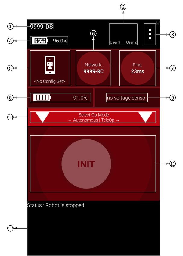
FTC Driver Station Overview
1. Name of this (Driver Station)
device
2. Gamepads connected to this
device
3. Popup menu
4. Battery level of this (Driver
Station) device
5. Name of Active Configuration
6. Name of connected Robot
Controller device
7. Ping
8. Battery level of Robot Controller
device
9. The voltage of the robot battery
10. Op Mode selection menu
11. Initialise/Enable/Disable menu
12. Output console
12
ftc-uk.org More Than Robots™Robot Controller and Driver Station Best Practices
Before the Competition
●● Do not install any applications other than the FTC Robot Controller and Driver
Station on the respective devices.1
●● One week before the competition, verify that:
»» the Android version is 6.0 or higher 2, and
»» the Robot Controller and Driver Station applications are version 4.0 or
higher and have the same version numbers.*
●● Add retention or strain relief to prevent the gamepad from falling onto the floor
and yanking on the USB ports. This helps prevent issues with intermittent
controller connections.
* Update the Android device and applications as necessary to meet these
conditions.
1Ifusing a ZTE speed device, the FTC Wi-Fi Direct Channel Changing App should
also be installed on the Robot Controller.
2For
Motorola Moto G (2nd Generation). For other Android devices, consult
in Game Manual Part 1.
At the Competition
●● Charge the Robot Controller and Driver Station devices when in the pit.
●● Disable login passwords or ensure everyone on the drive team knows the
password.
●● Do not plan on using internet access to do software updates. There will not
be any in the venue, and hotel Wi-Fi varies widely in quality. If updates are
necessary, contact a Control System Advisor in the pit.
Before each Match
●● Make sure each Android device is on and has the Robot Controller and Driver
Station applications open prior to the end of the previous match.
●● Close programmes that aren’t needed during the match when competing.
●● Ensure gamepads are assigned to the correct users.
13
ftc-uk.org More Than Robots™FTC Blocks Programming
This section provides basic code examples using various blocks. The explanations
of each sample are intentionally left minimal to encourage inquiry on how each
example works and ways in which it could be altered for the robot.
Accessing the Robot Controller Console
●● Install Google Chrome on a computer. Other JavaScript-enabled browsers may
be used, although Google Chrome is recommended.
●● In Robot Controller or Driver Station, select “Program and Manage”.
●● Connect the computer to the network displayed on the device with the
displayed password.Go to the displayed address in the computer’s browser to
access the robot controller console.
Creating a Benchtop Test Programme
The following instructions show how to create and run a basic drivetrain
programme. The programme requires motors to be plugged into motor ports 0 and
1 of the REV Expansion Hub and the gamepad to be plugged into the Driver Station.
1. In the Robot Controller or Driver Station, navigate to Configure Robot > New
> Expansion Hub Portal 1 > Expansion Hub 1 > Motors. For ports 0 and 1,
specify the type of motor attached and respectively name the motors “left_drive”
and “right_drive”. Press “Done” three times, then press “Save.” Name the
configuration and press “OK.”
2. In the Robot Controller Console, navigate to Blocks > Create New Op Mode.
Name the Op Mode and select BasicPOVDrive in the Sample field. Press OK.
Press “Save Op Mode.”
3. Press the Start and A button on the gamepad connected to the Driver Station.
4. Select the TeleOp Op Mode and press “INIT.” Press the play button, and the
motors should start responding to the joysticks on the gamepad.
FTC Blocks References
This reference manual provides brief descriptions of each feature of FTC Blocks
Programming. Because there are so many features, attempting to read this manual
can be overwhelming. It helps to remember that reference manuals are not meant
to be read like a tutorial or a training manual. Rather, it should be used more like a
dictionary where features can be looked up as needed.
The Blocks Programming Reference Manual can be found here:
goo.gl/ay2AC7
14
ftc-uk.org More Than Robots™Using Actuators
An actuator is a component of a machine that is responsible for moving and
controlling a mechanism or system. In simple terms, it is a “mover.”
Configuring Motors
In Robot Controller or Driver Station, navigate to Configure Robot > New* >
Expansion Hub Portal 1 > Expansion Hub 1 > Motors.
*If editing an existing configuration, select “Edit” under the correct configuration
name.
For each port, specify the motor type attached and the motor name. If no motors
are attached to a port, leave the Attached field as “Nothing” and the motor name
blank.
Setting Parameters
The following blocks should be run during initialisation, i.e. outside the loop.
Setting Direction
The above block can be found under Actuators > DcMotor in the left menu. Select
the motor name in the first parameter, and select FORWARD or REVERSE to set
the direction.
If using the REV HD Hex Motors on the drivetrain, this block is likely needed to
make the robot drive functionally.
Setting Zero Power Behaviour
The above block can be found under Actuators > DcMotor in the left menu. Select
the motor name in the first parameter, and select one of the following behaviours in
the second parameter:
●● BRAKE: Motor’s axle stops
●● FLOAT: Motor’s axle rotates but does not generate torque
15
ftc-uk.org More Than Robots™Setting Power
The above block can be found under Actuators>DcMotor in the left menu. Select
the motor name in the first parameter and enter a numeric value from -1.0 (full
reverse) to 1.0 (full forward) to set the power.
●● When the RunMode is RUN_USING_ENCODER or RUN_TO_POSITION the
value provided for power is used by the motor controller as the target speed
to adjust power levels provided to the motor. The maximum speed is based on
the brand and model of the motor specified in the configuration file.
Driving a Robot Using Differential Drive
There are two ways to control differential drives:
●● Arcade Drive: Two joystick axes respectively control speed and rotation.
●● Tank Drive: Two joystick axes respectively control the left and right speeds.
Motors often come in pairs in drivetrains; hence, dual blocks should be used, as
they allow two motors to be controlled within one block.
Arcade Drive
In the example below, the Y-axis of the left joystick controls speed, while the
X-axis of the right joystick controls rotation.
Tank Drive
In the example above, the Y-axis of the left and right joystick respectively control
the left and right speeds.
16
ftc-uk.org More Than Robots™Driving a Robot Using Mecanum Drive
In the example below, the X and Y-axis of the left joystick respectively control X
and Y speed, while the X-axis of the right joystick controls rotational velocity.
Controlling Servos
The block below can be found under Actuators>Servo in the left menu. Select the
servo name in the first parameter and enter a numeric value from 0 to 180 to set
On/Off Control of Motors
In the below example, if the value of condition is true, then the motor is on;
otherwise, it is off. Replace the condition with other Boolean statements to make
the example functional.
17
ftc-uk.org More Than Robots™Using Sensors
A sensor is a device, module, or subsystem whose purpose is to detect events or
changes in its environment and send the information to other electronics.
REV Robotics Expansion Hub Inertial Measurement Unit (IMU)
Use the IMU for the drivetrain to drive straight and turn accurately.
Configuring the IMU
In Robot Controller or Driver Station, navigate to Configure Robot > New* >
Expansion Hub Portal 1 > Expansion Hub 1 > I2C Bus 0.
*If editing an existing configuration, select “Edit” under the correct configuration
name.
Select “REV Expansion Hub IMU” under Attached and name the device.
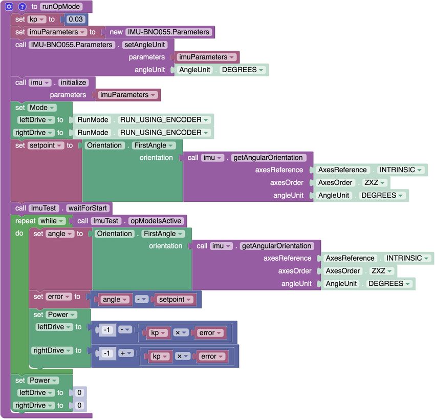
Using the IMU
In the example across, the orientation of the robot is read through the REV
Expansion Hub’s built-in IMU to make the robot drive straight.
Kp, the proportional gain constant, controls how sensitive the drivetrain is to
changes in its heading. Larger values make the drivetrain more responsive, but
excessively large values will cause the drivetrain to overcorrect itself, creating
undesired oscillations.
In order to use the IMU, it must be initialised using a set of parameters, which can
be set using the blocks under IMU-BNO055.Parameters. For this example, the only
important parameter is the Angle Unit.
The orientation of the Z-axis of the IMU is measured, as it is the first axis listed
in the axesOrder parameter of getAngularOrientation. The Z-axis is the axis
perpendicular to the REV Expansion Hub; therefore, the example assumes that
the Expansion Hub is laid flat. If the REV Expansion Hub is mounted in a different
orientation, change the measured axis to make the example functional.
18
ftc-uk.org More Than Robots™Encoder
Use encoders for the drivetrain to drive straight and to drive exact distances.
Alternatively, use encoders on mechanisms to accurately put it in various
positions.
Configuring the Encoder
The encoder is configured automatically when the corresponding motor
is configured. It is imperative that the correct motor type is selected when
configuring the motor.
19
ftc-uk.org More Than Robots™Resetting Encoders
The block below can be found under Actuators > DcMotor in the left menu. Select
the corresponding motor name of the encoder to be reset in the first parameter.
Using the Encoder
In the above example, the position of the motor is retrieved. Note that the unit
of the returned value is in counts. 1 rotation of the output shaft is respectively
equivalent to 288 and 1120 counts on the Core Hex and HD Hex Motors.
REV Robotics Colour Sensor
Use the colour sensor to detect the colour of objects or the robot’s distance from
an object.
Using the Colour Sensor to Measure Distance
In the example below, the distance measured by the sensor is retrieved. Specify
the unit of the value as centimetres, inches, metres, or millimetres.
REV Robotics Potentiometer
Use the potentiometer on mechanisms to accurately put it in various positions.
Support for this sensor will be available when REV Robotics provides
documentation.
20
ftc-uk.org More Than Robots™REV Robotics Touch Sensor
Use the REV Robotics Touch Sensor to limit a mechanism’s range of motion at a
hard stop or use it to detect when the robot has hit an object.
Configuring the Touch Sensor
In Robot Controller or Driver Station, navigate to Configure Robot > New* >
Expansion Hub Portal 1 > Expansion Hub 1 > Digital Devices.
*If editing an existing configuration, select “Edit” under the correct configuration
name.
For each touch sensor, select “Digital Device” as the attached device next to the
odd-numbered port of the two channels listed next to the digital port and name the
device.
Using the Touch Sensor
In the example below, the Op Mode is paused until the touch sensor is pressed.
Notice how the condition for stopping the loop is either the touch sensor being
pressed, or a stop being requested. This is so that pressing the stop button in
Driver Station will actually stop the robot.
REV Robotics Magnetic Limit Switch
Use the REV Robotics Magnetic Limit Switch to detect certain positions of a
mechanism.
The magnetic limit switch operates within the same principle as the touch sensor
in the software. Follow the same instructions as those of the touch sensor to
programme the magnetic limit switch.
REV Robotics 2m Distance Sensor
Use the REV Robotics Distance Sensor to measure an object’s distance from a
certain object.
Support for this sensor will be available when REV Robotics provides
documentation.
21
ftc-uk.org More Than Robots™Driver Station Inputs and Outputs
Assigning Gamepads
Press the Start and A button on the gamepad simultaneously to assign a gamepad
to User 1. Alternatively, press the Start and B button to assign a gamepad to User
2.
In the above example, several gamepad values are retrieved using blocks found
under Gamepad on the left menu. Select the gamepad name in the first parameter
and gamepad value in the second. Pay close attention to the type of value each
gamepad value returns.
Telemetry
Telemetry is a way to display information about the robot, such as sensor data,
motor status, and gamepad state, in the Driver Station. Displaying appropriate
data can help spot bugs in the program.
22
ftc-uk.org More Than Robots™Adding Data
The blocks below are found under Utilities>Telemetry in the left menu. The first
block adds numeric data, while the second adds textual data. The resulting
output of the blocks above would be:
key: 123
key: text
Replace the number and text parameters with relevant robot data and the key
parameter with text that makes the data identifiable.
Updating Data
If the telemetry data should be updated periodically, place the block below and
Telemetry.addData blocks inside the loop.
23
ftc-uk.org More Than Robots™MISCELLANEOUS
Communicating with other Team Members
For Software Engineers
●● Update the Project Manager on programming progress every session.
●● Discuss which actuators and sensors are necessary to make drivetrains and
mechanisms controllable with the Drivetrain and Manipulator Engineers.
●● Discuss safe programming practices with the Health and Safety Captain.
●● Help the Document Controller record the following in the Engineering
Notebook:
»» Team goals for control activities
»» Strategies for autonomous mode
»» Robot performance with and without added sensors
»» Requirements for successful autonomous operation
»» Performance improvements using algorithms and sensors
»» Testing results
●● Give IT support to the Media Coordinator.
●● Discuss autonomous strategies with the Strategy Officer.
●● Discuss wiring of actuators and sensors with the Electrical Engineers.
●● Discuss robot controls with the Drivers.
For Electrical Engineers
●● Update the Project Manager on progress with electronics every session.
●● Wire actuators and sensors for drivetrains and mechanisms with the Drivetrain
and Manipulator Engineers.
●● Discuss electronics safety with the Health and Safety Captain.
●● Discuss wiring of actuators and sensors with the Software Engineers.
●● Help the Document Controller record details on electronics in the Engineering
Notebook.
●● Help the Design Officer CAD electronics.
●● Help the Inventory Specialist keep an inventory of electronics.
Control Award
This section will be updated after kickoff.
24
ftc-uk.org More Than Robots™“The kids aren’t building
robots, the robots are building
the kids”
Dean Kamen, Founder
ftc-uk.org More Than Robots™You can also read