UHF RFID Antennas for Printer-Encoders- Part 3: Mobile Equipment
←
→
Page content transcription
If your browser does not render page correctly, please read the page content below
High Frequency Design                                           From November 2007 High Frequency Electronics
                                                                         Copyright © 2007 Summit Technical Media, LLC
             RFID ANTENNAS

                      UHF RFID Antennas for
                      Printer-Encoders—
                      Part 3: Mobile Equipment
                      By Boris Y. Tsirline
                      Zebra Technologies Corporation

                                           A
                                                   ntennas for RFID
               The final installment of            applications have
        this series looks at antennas              unique require-
         for mobile or portable RFID        ments, particularly for
         printer-encoder equipment          the small spaces inside
                                            portable or mobile equip-
                      ment. This final installment of this series of
                      articles looks at antennas for these types of
                      RFID printer-encoders, followed by summary
                      comments for the entire series and an exten-
                      sive list of references.

                      UHF Antennas for Mobile Printer-Encoders
                          Space saving for mobile RFID printer-
                      encoders is the biggest concern. Printers
                      require UHF antennas to be slim, because the
                      space available for their installation is very
                      limited. In addition to the geometric con-
                      strains, the antennas must enable the encod-
                      ing of short labels on a short pitch. Terminated
                      tapered resonant stripline TL antennas are
                      most qualified to meet these stringent require-
                      ments of the portable printers. The stripline
                      TL antennas are ultra-compact and conformal.
                      They fit in the space near the printhead and
                      can provide a short transponder placement
                      range. These antennas have received the high-        Figure 10 · Structure of terminated tapered
                      est acceptance for transportable and station-        stripline TL antennas: (a) single conductor TL
                      ary RFID printer-encoders. Antennas are pre-         antenna; (b) dual-conductor stripline TL
                      sented by the half-wave stripline (Fig. 10(a))       antenna.
                      and a double-conductor stripline (Fig. 10(b))
                      linear taper width TL.
                                                                           ders on the liner without activation of adja-
                      Antenna Structural Feasibility                       cent transponders. Examples of a stripline
                         Stripline TL antennas, which are arranged         and double-conductor stripline TL antennas
                      in parallel with the transponder in the encod-       are built on PCB substrate and have dimen-
                      ing area, occupy a very small space behind the       sions of 3.5 × 18 × 100 mm and 6 × 14 × 100
                      platen roller (Fig. 11). These antennas allow        mm, respectively. The internal conductor strip
                      selective encoding of densely spaced transpon-       (strips for a double-conductor stripline) is

18   High Frequency Electronics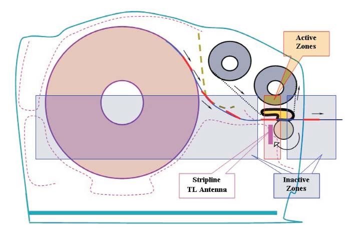
High Frequency Design
RFID ANTENNAS
Figure 11 · Printer zones with stripline TL antenna.
enclosed by two ground planes, stitched by vias along the
other three sides of the antennas to organize electric
walls and reduce parasitic radiation. The inner layer pro-
file (Fig. 10 (a)) is a modified bow-tie shape with the width
linearly varied from 9 to 4.5 and back to 9 mm for the
stripline and from 10 to 3 to 10 mm for two strips of the
double-conductor TL antenna. The dielectric constant of
both substrates is 4.25 and their height is 3.5 and 6 mm
accordingly. The length of the single stripline TL is 64 mm
and for double-conductor line is 57 mm. The narrow cen-
ter part of the inner layer is positioned close to the active
edge of the TL in order to concentrate magnetic field at
the center of this edge. This position of the maximum
magnetic field usually corresponds to the center of a tar-
geted for encoding transponder and supports an optimal
energy transfer for the symmetrical antenna-transponder
alignment.
Transponder Placement Boundaries
The single stripline TL antenna with a thickness of
only 3.5 mm improves printer’s performance by providing
a short transponder placement starting distance from the
label’s leading edge. It enables individual encoding of
short Smart Labels with a short pitch comparable to the
transponders width (Fig. 1 (d)). The double-conductor
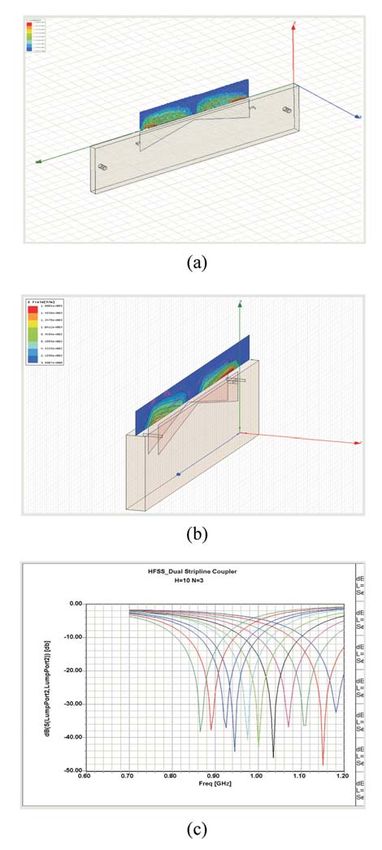
stripline TL antenna with a thickness of only 6 mm was Figure 12 · HFSS simulation of tapered stripline TL. (a)
developed for specific Smart Labels requiring a longer single conductor TL antenna—E field; (b) dual-conduc-
transponder placement range and higher antenna energy tor stripline TL antenna—E field; (c) S11 for dual-con-
efficiency than the single stripline TL antenna. ductor stripline TL antenna.
Encoding Field Intensity
Both antennas are in parallel alignment with target- coupling with a dipole type transponder antenna (Fig. 2).
ed transponders and are coupled with them by one open The capacitive coupling maintained by the stripline TL
long side edge. The electric field strength distribution antenna is relatively weak and permits very close posi-
simulated using Ansoft HFSS for the single stripline TL tioning to transponders. The stripline TL antenna is less
antenna (Fig. 12 (a)) and for the double-conductor spatially selective than the microstrip TL antenna but its
stripline TL antenna (Fig. 12 (b)) shows optimal shape for RF power margin is still about 3 dB without a significant
20 High Frequency Electronics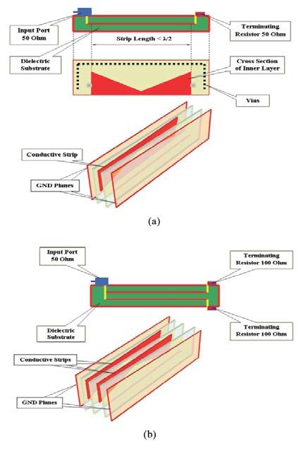
High Frequency Design
             RFID ANTENNAS

                                                             bandwidth. They are shorter than λ/2. A solution for
                                                             reflection loss S11 and geometry calculations for the dou-
                                                             ble-conductor TL antenna are obtained by HFSS simula-
                                                             tion (Fig. 12 (c)) and verified empirically. For the above
                                                             samples the single stripline (Fig. 13 (a)) and double-con-
                                                             ductor stripline (Fig. 13 (b)) TL antenna S11 parameters
                                                             demonstrate bandwidths in excess of 150 MHz. By vary-
                                                             ing individual strip lengths the multi-conductor stripline
                                                             TL antenna enables further increase in bandwidth,
                                                             antenna sensitivity, spatial selectivity, power efficiency
                                                             and transponder placement range.

                                                             Conclusions
                                                                 The article provided a thorough consideration of UHF
                                                             antennas for stationary and mobile printer-encoders.
                                                             Terminated TL antennas, while maintaining a consider-
                                                             able system power margin, can selectively interrogate
                                                             transponders without RF power suppression. Increased
                                                             available power delivered by the terminated resonant TL
                                                             antennas to the encoding interval tolerates usage of
                                                             transponders with large variation of their resonance fre-
                                                             quency and activation power threshold. Moreover,
                                                             enlarged bandwidth of terminated tapered resonant TL
                                                             antennas allowed using inexpensive RoHS PCB dielectric
                                                             materials with fairly wide deviations of permittivity,
                                                             thickness of a substrate and copper cladding.
                                                                 The proposed miniature stripline TL antennas, with
                                                             their compressed encoding range, permit portable print-
                                                             er-encoders to work with short, densely spaced Smart
                                                             Labels. The stripline antennas geometry, their conductive
                                                             strip dimensions, and bandwidth obtained from Ansoft
                                                             HFSS modeling for RFID 915 MHz band, have been veri-
Figure 13 · Reflection loss S11 for stripline TL antenna     fied empirically and found to be in a good agreement.
samples. (a) single conductor TL antenna: 4.5 × 9 × 64       Antenna analysis, mostly concentrated on microstrip and
mm; (b) dual-conductor TL antenna: 2× (3 × 10 × 57           stripline terminated TL, imposed no restrictions on the
mm).                                                         type of TL. Other TL structures, for example, the coplanar
                                                             waveguide or the slotline, may also be considered as
change in the encoding range. The double-conductor           building blocks of antennas for close proximity RFID
stripline TL antenna in comparison with a single strip TL    applications. Conclusively the stripline TL antenna is
has improved field intensity due to a higher SWR gener-      judged as a vital component for RFID applications involv-
ated by an increased load. Its power efficiency, spatial     ing equipment miniaturization or having spatial con-
selectivity and coupling grade with a transponder are also   straints for an antenna installation.
increased due to a larger effective edge area. The double        Besides RFID printer-encoders, there are many more
stripline TL antenna has an RF power margin in excess        applications of compact UHF antennas, including access
of 6 dB.                                                     control (Homeland Security market), item-level RFID for
                                                             conveyors, testing small transponders during their high
Impedance Bandwidth                                          volume manufacturing, quality validation in the Smart
   The port impedance of a single conductor stripline TL     Labels conversion process (Industrial market), and scan-
antenna is 50 ohms. For the double-conductor TL anten-       ners of RFID Smart credit cards (Financial market). It is
na the port impedance of 50 ohms is realized without an      believed that presented information on UHF antennas
additional matching network by connecting in parallel        will be helpful in selection of UHF Printer-Encoder and as
two strips, each loaded by a 100 ohm resistor. Both anten-   well as a tutorial guide for RFID newcomers. Although
nas utilize the same principles for bandwidth improve-       the terminated TL antennas have low far-field radiation,
ment as other tapered TL antennas and have a widened         they are still a source of UHF electromagnetic energy.

22   High Frequency Electronics
High Frequency Design
RFID ANTENNAS
Antenna mounting elements and nearby metal-plastic 9. D.M. Dobkin, S.M. Weigand, “UHF RFID and Tag
components can easily create a parasitic wave-guiding Antenna Scattering, Part II: Theory,” Microwave Journal,
structure for this energy transmission, causing excessive Vol. 49, No. 6, pp. 86-96, June 2006.
unintentional RF radiation that can interfere with the 10. (284) T. Breahna, D. Johns, “Simulation Spices
transponder encoding process. UHF terminated TL RFID Read Rates,” Microwaves and RF, pp.66-76, March
antennas have relatively low RF power efficiency in 2006.
exchange for their spatial selectivity and thus, represent 11. P.V. Nikitin, K.V.S. Rao, S.F. Lam, V. Pillai, R.
an improvement of energy conversion, and can be consid- Martinez, H. Heinrich, “Power Reflection Coefficient
ered as a subject for further research. Analysis for Complex Impedances in RFID Tag Design,”
Parts 1 and 2 of this series are available as PDF down- IEEE Transactions on Microwave Theory and Techniques,
loads from the Archives section of this magazine’s Web site: Vol. 53, No. 9, pp. 2721-2725, September 2005.
www.highfrequencyelectronics.com 12. C.A. Balanis, Antenna Theory: Analysis and
Design, 2nd Edition, John Wiley & Sons, 1996.
Acknowledgements 13. C. Capps, “Near field or far field?,” EDN Magazine,
The author would like to thank Zebra Technologies pp. 95-102, August 16, 2001.
Corporation and its associates K. Torchalski, Director of 14. I. Straus, “Loops and Whips, Oh My!,” Conformity,
RFID, and M. Schwan, System Manager for their helpful pp. 22-28, August 2002.
and productive discussions regarding UHF RFID Printer- 15. I. Straus, “Near and Far Fields—From Statics to
Encoders development, M. Fein, RF Engineer for his Radiation,” Conformity, pp. 18-23, February 2001.
HFSS counseling, and R. Gawelczyk, Engineering 16. B.Y. Tsirline, “Spatially Selective Antenna for Very
Technician for his outstanding support and assistance in Close Proximity HF RFID Applications-Part 1,” High
antenna fabrication, testing and evaluation. The author Frequency Electronics, Vol. 6, No. 2, pp. 18-28, February,
also would like to thank S. Kovanko, EE Engineer for 2007.
carefully reading parts of the manuscript. 17. J.D. Griffin, “A Radio Assay for the Study of Radio
Frequency Tag Antenna Performance,” MSEE Thesis,
References Georgia Institute of Technology, August 2005.
1. “Item-Level Visibility in the Pharmaceutical Supply http://etd.gatech.edu/theses/available/etd-05022005-
Chain: a Comparison of HF and UHF RFID Technologies,” 142356/unrestricted/griffin_joshua_d_200508_mast.pdf
White Paper, Philips Semiconductors, TAGSYS, Texas 18. S.G. Downs, “Why Antennas Radiate,” QEX
Instruments Inc., July 2004. http://www.tagsysrfid.com/ Magazine, pp. 38-42, January/February 2005.
modules/tagsys/upload/news/TAGSYS-TI-Philips-White- 19. R. Schmitt, “Understanding Electromagnetic
Paper.pdf Fields and Antenna Radiation Takes (Almost) No Math,”
2. M.C. O’Connor, “Study Shows Big Growth for RFID EDN, pp. 77-88, March 2, 2000.
Printer-Encoders,” RFID Journal, Inc., July 25, 2006. 20. G. Kumar, K. P. Ray, Broadband Microstrip
http://www.rfidjournal.com/article/articleprint/2515/-1/1/ Antennas, Artech House, 2003.
3. M.C. O’Connor, “RFID Changing Buying Behavior,” 21. J.F. Feltz, J.A. McCurdy, L.D. Neuhard, “RFID
RFID Journal, Inc., July 21, 2006. http://www.rfidjournal. printer and antennas,” U.S. Patent Application
com/article/articleprint/2508/-1/1/ 20050280537, December 22, 2005.
4. L.G. Maloratsky, Passive RF & Microwave 22. T.A. Chapman, R.E. Schumaker, A. W. Edwards,
Integrated Circuits, Newnes, 2003. S.S. Morris, J.P. Harkins, B.S. Jarvis, “RFID tag and print-
5. K.V.S. Rao, P.V. Nikitin, S.F. Lam, “Antenna Design er system,” U.S. Patent 7,066,667 B2, June 22, 2006.
for UHF RFID Tags: A Review and a Practical Appli- 23. L. Beauvillier, M.J. Brady, D-W. Duan, D.J.
cation” IEEE Transactions on Antennas and Propagation, Friedman, P.A. Moskowitz, P. Murphy, “Method and appa-
Vol. 53, No. 12, pp. 3870-3876, December 2005. ratus for testing RFID tags,” U.S. Patent 6,104,291,
6. “Texas Instruments Gen 2 Inlay,” RI-UHF-00C02 - August 2000.
Product Bulletin, 2006. http://www.ti.com/rfid/docs/manu- 24. R.E. Collin, Foundations for Microwave
als/pdfspecs/ri-uhf-00c02_prodbulletin.pdf Engineering, 2nd Edition. Wiley-IEEE Press, 2001.
7. D.M. Dobkin, S.M. Weigand, “UHF RFID and Tag 25. G.B. Barrus, R.E. Schumaker, , A.W. Edwards, K.M.
Antenna Scattering, Part I: Experimental Results,” Smith, D.C. Gibbs, R.Jr. Concepcion, “RFID tag, antenna,
Microwave Journal, Vol. 49, No. 5, pp. 170-190, May 2006. and printer system,” U.S. Patent 7,037,009 B2, May 2,
8. D.M. Dobkin, T. Wandinger, “A Radio-Oriented 2006.
Introduction to RFID—Protocols, Tags and Applications,” 26. G.B. Barrus, R.E. Schumaker, A.W. Edwards, D.C.
High Frequency Electronics, Vol. 4, No. 8, pp. 32-46, Gibbs, K.M. Smith, R. Concepcion Jr. , “RFID tag, anten-
August 2005. na, and printer system,” U.S. Patent 6,929,412 B1, August
24 High Frequency Electronics16, 2005. at Automotive Electronics and Equip- spatially selective transponder 27. D.M. Pozar, Microwave ment Corp., Russia, developing mili- encoding modules used throughout Engineering, 2nd Edition, John Wiley tary and aerospace electronic sys- the corporation divisions for RFID & Sons, 1998. tems. He has been in the Automatic labels and cards printers. Dr. Tsirline 28. K.C. Gupta, R. Garg, I. Bahl, P. Identification and Data Capture holds three non-classified Russian Bhartia, Microstrip Lines and industry since 1995. He managed the and two US patents and has numer- Slotlines, Artech House, 1996. development of Zebra’s first HF RFID ous pending patents for RFID 29. L. Young, “The Quarter-Wave printer-encoder and established the enhancements. He can be reached by Transformer Prototype Circuit,” IRE design methodology for HF and UHF e-mail at BTsirline@zebra.com. Transactions on Microwave Theory and Techniques, pp. 483-489, September 1960. 30. G. Matthaei, L. Young, E.M.T. Jones, Microwave Filters, Impedance- Matching Networks, and Coupling Structures, Artech House, pp. 255- 354, 1980. 31. R. W. Klopfenstein, “A Transmission Line Taper of Improved Design,” Proceedings of the IRE, Vol. 44, pp. 31-35, January 1956. 32. R.P. Hecken, “A Near- Optimum Matching Section Without Discontinuities,” IEEE Transactions on Microwave Theory and Techniques, Vol. MTT-20, No. 11, pp. 734-739, November 1972. 33. J.-T. Kuo, “Riccati Matrix Differential Equation Formulation for the Analysis of Nonuniform Multiple Coupled Microstrip Lines,” IEEE Transactions on Microwave Theory and Techniques, Vol. 44, No. 6, pp. 880-886, June 1996. 34. K. Lu, “An Efficient Method for Analysis of Arbitrary Nonuniform Transmission Lines,” IEEE Transac- tions on Microwave Theory and Techniques, Vol. 45, No. 1, pp. 9-14, January 1997. 35. “3D Electromagnetic-Field Simulation for High-Performance Electronic Design,” Ansoft Corp. Author Information Boris Y. Tsirline is the Principal Engineer at Zebra Technologies Corporation. He received a BS and MS degrees in RF & Microwave Engineering from Moscow Aviation University, Russia in 1973 and a PhD in EE from Moscow State University in 1986. Before moving to the US in 1992, he served as a Director of R&D
You can also read