User Guide - Cube Controls
←
→
Page content transcription
If your browser does not render page correctly, please read the page content below
User Guide
GT Wireless eSports Racing Wheel   1
Due to continuous improvement, the actual product may differ
from the manual.

This manual is for reference only.
For info or support contact us at
hello@cubecontrols.com

or visit us at
www.cubecontrols.com
2
SAFETY NOTICE
Please read the Manual carefully before you use the racing wheel.
Please do not open the racing wheel, otherwise the supplier will not afford
warranty service.
This product does not have waterproof function, please keep it away from
rain, moisture and other items containing liquid such as vape, cup and so
forth.
This wheel is designed for simulation use only.
Disconnect the USB cable from both sides if you will not use this product
for a long time.

Should you find any problems in your wheel, please contact us at
hello@cubecontrols.com, do not repair it by yourself.

                                                                              3
INTERFACE INTRODUCTION
LEFT TOGGLE RIGHT TOGGLE
STATUS LED STATUS LED
L TOGGLE R TOGGLE
DOWNSHIFT UPSHIFT
2 WAY TOGGLE 2 WAY TOGGLE
ENCODER ENCODER
ENCODER ENCODER
4POWER BUTTON WIRELESS ANTENNA
5SYNCING TO YOUR SIMUCUBE Turn on the steering wheel by pressing the power button indicated in the picture above. The steering wheel enters discovery mode and announces itself to the SIMUCUBE base for 30 seconds. Discovery mode can also be activated by pressing both paddle shifters simultaneously. When connecting to a SIMUCUBE base for the first time, it is required to manually select the wireless button plate module from the list provided by SIMUCUBE configuration software True Drive. Double click on the device name to establish the connection. By checking the “connect automatically to paired devices” box at the bottom of the window, the wheel will be connected as soon as it enters discovery mode by power-on or pressing both paddles for 5 seconds. Connection to SIMUCUBE base can be closed by pressing again both paddle shifters for 5 seconds or simply by turning off the wheel. The steering wheel status changes are shown by a blinking status LED as seen in the drawing on page 3: Discovery mode: continuous blinking at a high frequency Connected to a SIMUCUBE controller: 3 blinks at a medium frequency Disconnected from SIMUCUBE controller: 10 blinks at a slow frequency 6
B AT T E RY I N FO R M AT I O N
The Formula wireless wheel features a 3.7V 1500mAh LiPo battery that
should allow around 40 hours of use before needing to be charged again.
Battery status can be seen via the LED indicator on the front of the wheel
as drawing on page 3.
LED indicator status:
Off: battery OK
Red: battery low, needs recharging
Blue: battery fully charged
Once the battery indicator LED turns red, there are about 2 hours of use left.
The battery can be charged via the supplied coiled cable using any
USB port.
Charging time it’s around 2 hours, and the steering wheel can be used
even while charging.
Steering wheel must be switched ON while charging.

                                                                             7
C H A R G I N G T H E B AT T E RY
To charge the battery connect the steering wheel to your PC by only using
the provided cable.
Please note that the wheel connector it’s keyed as the picture below, so it
fits only one way.
Once the plug it’s correctly seated into the body receptacle, secure it by
turning the retaining ring as bottom right picture.
IMPORTANT: do not over-tighten the ring. Just screw it completely
until it stops rotating, do not apply excessive force.
Alignment key
8WH E E L I N STA L L AT I O N
Our universal hub on the back of the wheel body allows the user to install
various adapter, or even connect it directly to your FFB base.
Highlighted in blue the M5x0.8 metric holes. In gray, 5,5mm through holes.
Both of them are available in 70mm or 50.8mm bolt pattern.
Through holes are rotated by 180°, so flipping your adapter to match the wheel
hub may be needed.
Please refer to your adapter or motor manufacturer to ensure compatibility.
Inner
50.8mm
pattern
Outer
70mm
pattern 9PA D D L E S A DJ U S T M E N T Shift paddles can be easily adjusted to better suit your hand size and driving preferences. T10 drive needed. Length can be adjusted by slightly loosening the two screws highlighted in the right picture, and sliding forward/backwards the carbon paddle. Reach can be adjusted by slightly loosening the two screws highlighted as the right picture and the two on the opposite side of the shifter as pointed by the small arrows, then rotating the lever body upwards/downwards. You may need to apply a bit of force. 10
USEFUL TIPS
Each wheel comes with a full sheet of stickers and a set of plastic tweezers
useful to install them as your liking.
Before applying the sticker make sure the surface it’s clean.
Black and white long labels are designed to be placed over the dial
setting name:

Try to install the USB coiled cable by wrapping it loosely on your FFB motor
shaft/adapter in such a way that it will not suffer any strain even when
doing full opposite steering rotations.

                                                                               11
SHIFTERS MAINTENANCE
If lubricant dries up you might experience the paddle shifter not coming back
to its original position freely.
Once a year it’s highly recommended to put a really small drop of lubricant
(sewing machine oil or similar) on the points as the drawing on the right
indicates, just where the lever body touches the base of the shifter when
pressed down.
A small drop of lubricant on the contact point of the stainless steel pin as
indicated by the arrow will help as well.
Do not use any spray products such as WD40 or similar.
Shifter unit bottom view
12A DJ U S T I N G S H I F T PA D D L E S
ACT I VAT I O N P O I N T
Introduction:
Whilst all the racing wheels are already tested, you might need to adjust the
shifter sensor activation point for a correct use on your setup.
Needed tools:
Torx T10 drive and a small philips screwdriver (both provided).
Accessing the trimmers
Locate and remove the two Torx screws on the back of the wheel as
highlighted in the next picture.
Do not use any spray products such as WD40 or similar.
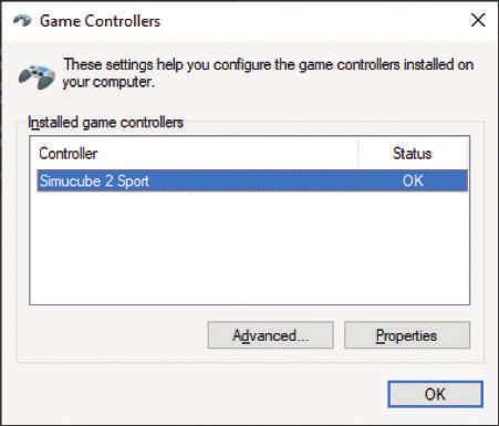
13Select your Simucube controller Go to Control Panel and access the Game Controllers window. Select your Simucube base from the list and open the properties panel. You should now see a window that displays all your controllers buttons: 14
Adjusting the trimmers
Carefully place a small philips screwdriver inside the screw hole leaved by
the screw you removed in the previous step, and move it slightly until it
engages the trimmer. It sits around 10mm below the surface of the main
body.
There is one trimmer for each right (up-shift) and left (down-shift) paddles.
Press the paddle you are adjusting and keep it pressed, rotate the trimmer
slowly clockwise or anticlockwise until the down-shift button (9) or up-shift
button (10) are on.
Please notice that the adjustment trimmer have end points on both
ends, do not force the rotation if you reach them.
Release the shifter, remove the screwdriver and check if the shifter is now
working properly. If needed, please, do repeat this process for the other
paddle.
Once you are done with the calibration, put back in place the Torx screws
you removed at the beginning.

                                                                              15
16 W W W.CU B E CO N T R O L S .CO M
You can also read