Validation of Transmission Loss Simulation Approach with Goal to Estimate Launch Vehicle Internal Cavity Acoustics - NASA
←
→
Page content transcription
If your browser does not render page correctly, please read the page content below
https://ntrs.nasa.gov/search.jsp?R=20150016417 2019-08-21T13:08:29+00:00Z

      Validation of Transmission Loss Simulation
      Approach with Goal to Estimate Launch Vehicle
      Internal Cavity Acoustics

              Andrew M. Smith                       Bruce T. LaVerde, ERC Inc
           Vibroacoustics Specialist               Vibroacoustics Lead Engineer
  Vehicle Loads and Strength Branch (EV31)          ESSSA Contract Support to
    NASA Marshall Space Flight Center        Vehicle Loads and Strength Branch (EV31)
                                                NASA Marshall Space Flight Center

  NASA/Marshall Space Flight Center/
  Vehicle Loads and Strength Branch (EV31)
  2-4 June 2015

© The Aerospace Corporation 2010
  © The Aerospace Corporation 2012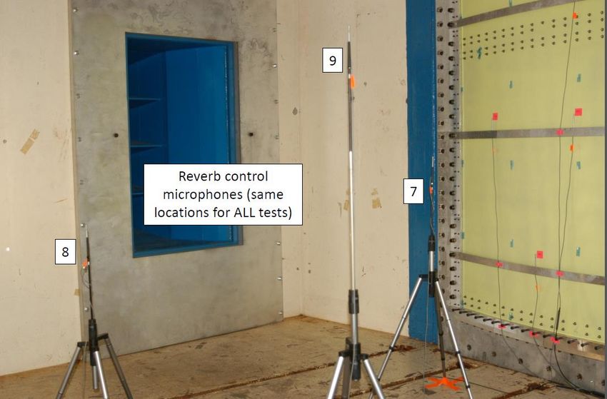
Agenda

•   Introduction/Motivation - Use of the Lorch Results
      – Comparison of measured average sound pressure levels (SPLs) in two
         reverberant rooms is the standard approach (Reference ASTM E90). Both
         Source room and receiver room are reverberant.
      – Lorch used an approach based on sound intensity that allowed the receiver
         room to be anechoic rather than reverberant.
      – Lorch’s approach assumptions should affect the measurement setup for a
         transmission loss test.
•   Response Analysis Choices to Generate Hybrid Transmission Loss Estimate
•   Panel Design Factors - Finite Element Model of Large Grid Test Article Panel
•   Evaluating the applicability of a single panel transmission loss result for estimating
    the internal cavity acoustics of a launch vehicle compartment.
•   Sound Power Estimates for Cavity Acoustic Response using VA one
•   Conclusions and Forward Work

                                             2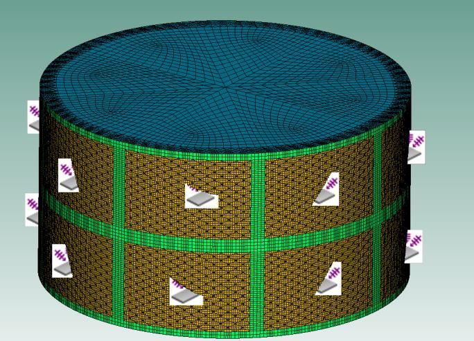
Introduction/Motivation
            Use of the Lorch 1980 Published Results
•   Lorch, D. R., AIAA-80-1033, “Noise Reduction Measurements of integrally
    Stiffened Fuselage Panels,” Douglas Aircraft Company, McDonnell Douglas
    Corporation, Long Beach California. AIAA 6th Acoustics Conference, June 1980.
•   Lorch measured transmission loss across a panel separating a reverberant source
    room from an anechoic receiver room. This differed from the standard approach
    where both source and receiver rooms were set up to be reverberant.
•   An attempt to verify the Hybrid Transmission Loss results using a NASTRAN FEM
    and VA One Diffuse Acoustic Field by comparison to the Lorch measured results.
•   We have also examined his assumptions to provide a suitable test configuration in
    the MSFC facility. Similar to Lorch, MSFC has an anechoic chamber adjoining the
    Reverberant Chamber. The goal is to measure:
      – The diffuse field in the source room
      – The plane waves radiated from the panel in the near field in the receiver room.
•   The published Lorch data provides an opportunity to evaluate/verify from
    measurements the estimate of “Hybrid Transmission Loss” produced using
    NASTRAN Modes as an input to VA One Response.
•   We can also illustrate how useful the Transmission Loss (TL) results might be to
    guide a Cavity internal acoustics assessment.
                                           3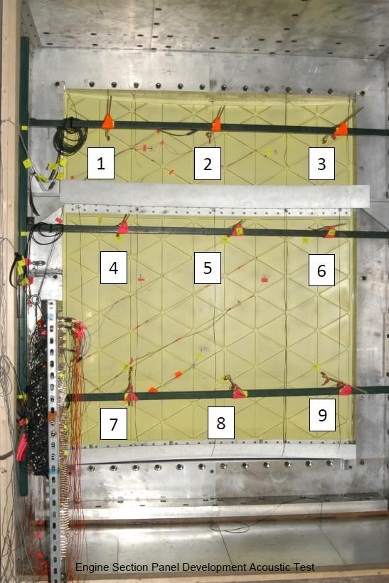
Approach Assumptions Affect the
Measurement Test Setup – Reverb Side

           •   6 microphones 1 – 1.5 in
               from panel
           •   3 microphones on tripod
               near center of room used
               to measure the Diffuse
               Field.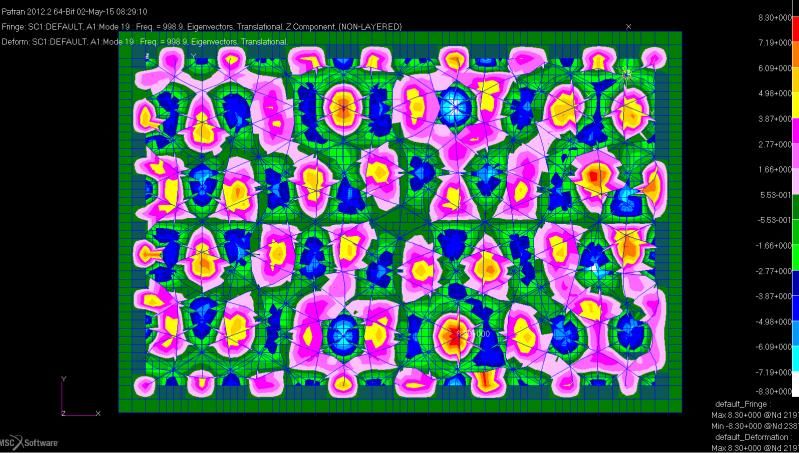
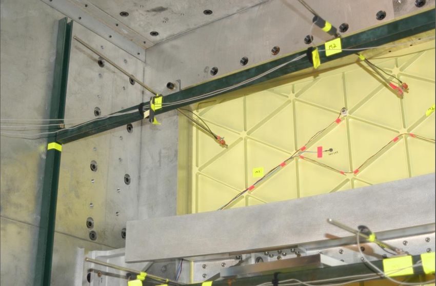
Approach Assumptions Affect the
       Measurement Test Setup – Anechoic Side

•   9 microphones located 1 inch away from
    interior panel wall. Used to measure the
    progressive plane waves radiated from
    panel.
Approach Assumptions - Lorch Equations

•   Required equations for a reverb to anechoic chamber test setup
              Not appropriate to
              measure Average SPL in
              Anechoic Receiver room.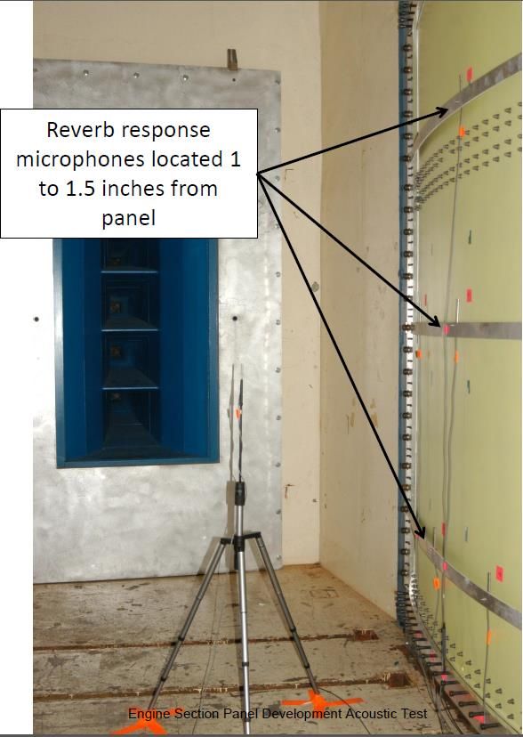
Hybrid SEA/FEM Response Simulation Choices
                  Lorch Transmission Loss Results
•   The validation presented here addresses only the measured results published by
    Lorch for one of his Isogrid Panel test articles (Large Grid Test Article).
•   FEM representing the Large Grid Test Article was prepared in NASTRAN, from the
    few details he tabulated in his paper.
•   Important Factors for the Finite Element Analysis:
     –   Boundary Conditions
     –   Damping
     –   Frequency Resolution
     –   Mesh Density
     –   Forcing Function Patch Resolution.

•   Hybrid Transmission Loss was
    calculated in VA One using a
    1/36th octave band resolution.
    Response was later filtered to
    convert it to 1/3rd octave for
    comparison to the Lorch published
    results.

                                              7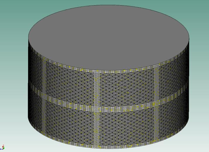
Design Details and FEM Choices for
Modeling the Large Grid Test Article
        Approach validation Trials With the Similar
        Shell explicit FEM
             •   Finite Element Mesh was made fine enough to include nodes
                 in the interior of the isogrid cell in this case 4 nodes interior
                 that are not congruent with the rib nodes
             •   The 4.16” triangle height was broken into four units in one
                 direction and three units in the other direction.
             •   Structural modes may limit frequency range more than the
                 forcing function resolution.
             •   Approximate 1 inch spacing between element centers
                 corresponds to a patch density adequate for about 3000 Hz
                 (Reference Smith 2013)

                           8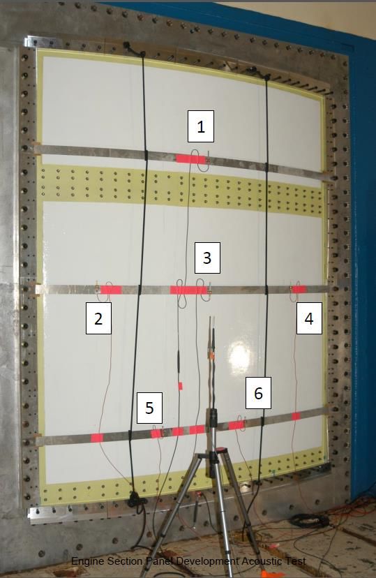
Comparison of Hybrid FE Results Estimating
    Transmission Loss to Measured
            •   A colleague who became interested in our results, shared
                a variation where the mesh density of the FEM was
                refined in the hope of pushing the analytical assessment
                to Higher frequencies.
            •   Appreciation is expressed to Justin Harrison (CRM
                Solutions Incorporated) who shared the fine mesh results
                in time to include them here by permission.

                            9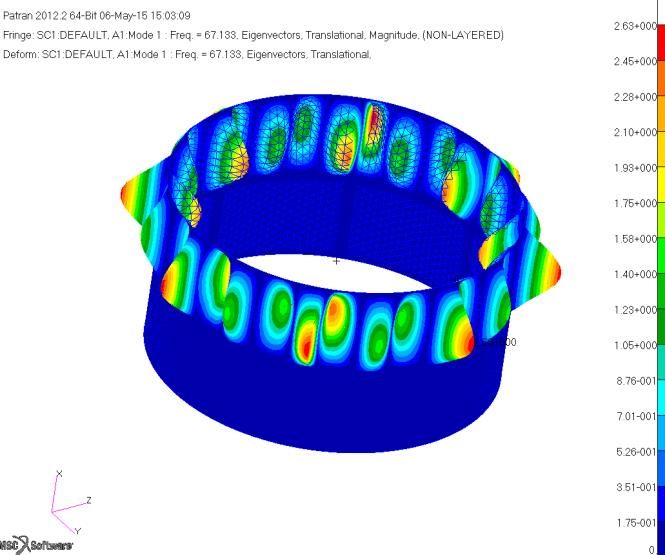
Panel Design Factors
Panel Bending Modes vs Pocket Modes
         Approach validation Trials
           •   The mass of the ribs is carried along in the Panel Bending
               Modes.
           •   The mass of the ribs does not participate once the wavelengths
               are short enough to set up Pocket Modes in the isogrid cells.
           •   Pocket Modes radiate sound to the interior more efficiently.

                                      1000
                                      Hz

                                      1600
                                      Hz

                          10
Panel Design Factors
Determine Frequency Range Pocket Modes are Observed
• Suggest simple estimate of the frequency range where pocket
modes probably begin to diminish transmission loss.
• Calculate Fundamental Mode for Simply Supported
Equilateral Triangle Using breakout model same material,
pocket dimensions and skin thickness.
1000
1487 Hz
Hz
1600
Hz
11Panel Design Factors
Panel Bending Coincidence
SEA was used for a quick estimate of Wave numbers.
• Fluid structural coincident frequency also may occur above 1000
Hz according to the smeared property estimate of the wave
numbers
• Smeared properties follow the approach of the Isogrid Design
Handbook (Reference Meyer 2004).
1000
Hz
1600
Hz
12Hypothetical Launch Vehicle Compartment
Assembly of 16 similar panels into Cylinder
• We can determine Total Noise Reduction from a
Hybrid Analysis by subtracting the resulting
estimate for Internal Cavity acoustics from the
External Acoustic Excitation.
• Hypothetical Cylindrical Launch vehicle section
fashioned from 16 panels with Lorch Large Grid
design parameters. Radius 105.4 in. Height 112 in
• Identical DAF excitation applied to each panel.
Noise reduction
resembles Transmission
Loss at High Frequency
13Is Single Panel Measured TL useful for
Assessing Cavity Acoustic Environment?
• In this example, the boundary conditions for
the panel have changed fairly drastically
from the Flat Panel Test.
• The single panel had been clamped on four
sides. In this integrated configuration it is
welded to the next panel on 3 sides.
• The mode shapes that span two panels
axially were not possible in the Lorch Flat
Panel Test Configuration.
The transmission loss
results may have been
more transferable to a
Design that
included Ring
Frames.
14Measured Panel Transmission Loss was not so
helpful in the Low/Mid Frequency Range?
• In the first Cylindrical case assessed the Transmission Loss seems to be a helpful
predictor only at frequencies from 700 to 1000 Hz.
• In the Cylindrical Hybrid FEM analysis, the estimated internal acoustics respond
quite close to external acoustics in the range from 100-250 Hz. Seeming to
contradict both the transmission loss test and the matching single panel Hybrid
FEM analysis.
• A quick assessment using SEA to estimate Panel and cavity wave numbers
(slide 12) seems to indicate that the diffuse field should be very inefficient eliciting
resonant response from the structure in the 100-250 Hz range.
• We turn to Finite Element Analysis to provide more information.
– Boundary conditions and system architecture effects can be understood from
the mode shapes of the cylinder we are assessing.
– Mode shapes in this unsupported architecture tend to span across two panels
in the axial direction.
– This ability to develop large bending shapes across two panels was not
possible in the smaller clamped panel configuration of the transmission loss
test.
15Lorch Panel adjustment Flat to Curved
16 similar panels used to build up Cylinder
• At High frequency the TL could be used in the
typical Sabine equation where other factors such as
the cavity fluid and surface absorption are added to
the TL as additional sources of noise reduction.
• Cavity absorption was assumed at 1% in the
analysis there were no treatments applied to the
surfaces of the panels. Constraint added along midline between fwd and aft welded
panels approximating a ring frame effect on panel modes.
The measured TL acts like cylindrical vehicle Total Noise
Reduction over the frequency range from 700-2000 Hz.
Fixed constraints added to center grids
prevented some mode shapes - increased
rejection of Noise in low – mid frequency bands
16Compare Noise Reduction Estimate to Measured
Statistics From Development Flights
• The STS & Saturn V data seems to
confirm that a cylindrical vehicle
Sharp reduction in Noise
compartment can be fairly Reduction below 300 Hz
transparent to sound in the supported from Flight data
Frequency range from 80-250 Hz.
• Also, a corresponding increase in
noise reduction in the lowest
frequency bands seems consistent
with these STS observations from
measured data.
The Noise Reduction Estimates from Lorch Panel Studies
remain consistent with Single Panel Transmission Loss
spectrum shape in bands from 500-2000 Hz.
17Cylindrical Assessment Modes
With Additional Center Constraint
• A NASTRAN Trial was made where the
central nodes dividing the cylinder forward
and aft were fixed.
• This resulted in mode shapes that are more
like the flat panel modes apparent during
the flat panel test.
• If the vehicle incorporated ring frames that
might be sufficient to make the test results
more useful for Launch vehicle estimates.
Suggested Lessons:
Choose the right test article to
assess your vehicle
architecture.
Avoiding Longer bending
modes using frames can
make a vehicle section better
able to reject sound energy.
18Was the Measured Panel Transmission Loss a useful
guide in the Low to Mid Frequency Range?
• Perhaps we can say that The measured TL approximates the Noise Reduction for the
hypothetical cylindrical vehicle within 2-3 dB over the freq. range from 300-2000 Hz.
• Also, it was observed that at High frequency the TL resembled the shape of the total noise
reduction, but was lower in magnitude than the Total Noise Reduction only at High Frequency.
– The Transmission Loss provided by the panel is only a portion of the total noise reduction.
– Other factors such as absorption by the cavity fluid, and absorption by the surfaces
bounding the cavity also contribute to the total noise Reduction.
– The simplicity of the Hybrid Response Analysis that developed the internal acoustic noise
estimate may have contributed to the dip of Total Nosie Reduction below measured TL.
• Coupling loss reduced by the absence of forward or aft structures
• No treatments were applied to surfaces. 1.0% absorption is a minimum typical of a
reverberant chamber from T60 tests. We expect launch vehicle compartments to
contribute more.
• Similar results have come to light where low Noise Reductions Measured in the mid frequency
range from Saturn V and STS Flights.
• Since the modes shapes of the panels will be somewhat different in any vehicle assembly, we
should, therefore, recognize that measured TL will most useful in mid-to-high frequency range.
19Conclusions and Forward Work
• Hybrid Transmission Loss calculations using VA One were verified using Lorch’s
Measured results were verified for a rib stiffened Isogrid Panel.
– Finite element model must include nodes at the center of each Cell.
– Damping, Mesh Density, and frequency resolution , corresponding to the analytical
solution were provided.
• Demonstration of how the measured transmission loss from 1 flat panel might feed
into a system assessment estimating internal cavity acoustic environments.
– Transmission loss is not total noise reduction.
– Transmission loss can be used to help define the terms of a power balance equation,
where all the loss factors are included.
• When making use of TL from test verify that the test article and system architecture
compare well to support the objectives for the test. Since Hybrid Transmission Loss
Predictions are becoming fairly reliable, be sure to match your vehicle architecture
when conducting breakout studies.
20Conclusions and Forward Work
• Impact of Lorch’s assumptions/ methodology on test setup’s was explained.
Placement of microphones is important:
– Goal is to measure diffuse field on reverberant side of panel. Microphones sample field at
least 30 inches form walls and surfaces.
– Goal is to measure plane waves amplitudes radiated on Anechoic side in Receiver room..
Microphones sample field at close spacing to the panel.
• Forward Work:
– Account for Venting and Other Effects that make an actual vehicle compartment different
that the simple cylinder assessed.
– Develop better understanding of the Surface Absorption effects.
– Develop understanding of Transmission Loss and Noise Reduction for such pressure fields
as are present at Transonic and Max Q.
21References
ASTM E90 -81, ”Standard Method for Laboratory Measurment of Airborne Sound Transmission Loss of Building Partitions,” ASTM,
Philadelphia, PA, 1981.
Lorch, D. R., AIAA-80-1033, “Noise Reduction Measurements of integrally Stiffened Fuselage Panels,” Douglas Aircraft Company, McDonnell
Douglas Corporation, Long Beach California. AIAA 6th Acoustics Conference, June 1980.
Manning, J. E.., “The Role of Absorption in Reverberant Acoustic Test Facility Design” Cambridge Collaborative, 26th Aerospace Testing
Seminar, March 2011.
Meyer, R. R.., et all, MDC G4295A, “Isogrid Design Handbook,” Prepared for Marshall Space Flight Center (NASA Contract NAS 8-28619),
McDonnell Douglas Corporation, Huntington Beach California. Original relaease 1973, Revised 2004.
Davis, R. B., Fulcher, C., “A Component Mode Synthesis Approach for Calculating the Vibroacoustic Response of Mass Loaded Panels,”
Presentation to the NESC Loads & Dynamics TDT Face-to-Face Meeting, NASA/MSFC/ER41, April 2013.
Frady, G., Duvall, L.., Fulcher, C.., LaVerde, B., Hunt, R.., “Test-Anchored Vibration Response Predictions For An Acoustically Energized
Curved Orthogrid Panel With Mounted Components,” Proceedings of JANNAF’s 8th Modeling and Simulation Subcommittee (MSS),
December 2011.
Peck, J., Smith, A., Fulcher, C., LaVerde, B., Hunt, R., “Development of Component Interface Loads on a Cylindrical Orthogrid Vehicle Section
from Test-Correlated Models of a Curved Panel,” Proceedings of 2011 Spacecraft and Launch Vehicle Dynamic Environments
Workshop, June 2011.
Smith, A., Davis, R.B., LaVerde, B., Hunt, R., Fulcher, C., Jones, D., Band, J., “Calculation of Coupled Vibroacoustics Response Estimates
from a Library of Available Uncoupled Transfer Function Sets,” AIAA SDM April 2012.
Smith, A., LaVerde, B., Hunt, R., Jones, D., Waldon, J., Towner, R., “A Patch Density Recommendation based on Convergence Studies for
Vehicle Panel Vibration Response resulting from Excitation by a Diffuse Acoustic Field,” AIAA SDM April 2013.
Smith, A., Parsons, D., Teague, D., “SPIE ISPE Vibroacoustics and Shock Assessment and Models Report,” SLS-SPIO-RPT-034, version 2,
change 1, NASA Marshall Space Flight Center, October 28, 2014.
22Backup Slides
Hybrid Transmission Loss Studies
are Simple Assessments:
• FE of Partition
• SEA DAF applied Excitation to
one side
• SEA SIF Receiver attached to
opposite side
Adaptable to more than Just Flat
Panel studies.
Consider Hybrid Transmission
Loss Studies for larger more
complex subsystems.
23Backup Slides
Modes in Band for the Cylindrical Studies
24“Validation of Transmission Loss Simulation
Approach with Goal to Estimate Launch Vehicle
Internal Cavity Acoustics”
Andrew M. Smith Bruce T. LaVerde, ERC Inc
Vibroacoustics Lead Engineer
Vibroacoustics Specialist
ESSSA Contract Support to
Vehicle Loads and Strength Branch (EV31)
NASA Marshall Space Flight Center Vehicle Loads and Strength Branch (EV31)
NASA Marshall Space Flight Center
© The Aerospace Corporation 2010
© The Aerospace Corporation 2012You can also read