KEYSIGHT 34420A NANOVOLT/MICRO-OHM METER - INCAL ...
←
→
Page content transcription
If your browser does not render page correctly, please read the page content below
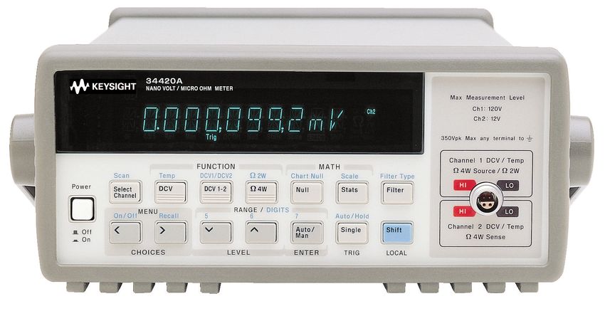
DATA SHEE T

Keysight 34420A
NanoVolt/Micro-Ohm Meter
Notice: The 34420A Micro Ohm meter will be discontinued on December 1st, 2021. The last day to place order
for this product is November 30, 2021. Keysight will continue to provide world-class support for this product for
the standard period of 5 years.

–   7½ digit resolution
–   100 pV, 100 nΩ sensitivity
–   1.3 nVrms, 8 nVpp noise performance
–   Built-in low noise 2 channel scanner
–   Direct SPRT, RTD, Thermistor, and Thermocouple measurements
–   BenchVue now inlcuded
Nanovolt performance at a microvolt price                             SPRT measurements
The Keysight Technologies, Inc. 34420A nanoVolt/micro-Ohm             Built-in ITS-90 conversion routines accept the calibration
meter is a high-sensitivity multimeter optimized for performing       coefficients from your SPRT probe for direct temperature
low-level measurements. It combines low-noise voltage                 measurement and conversion. Thermocouples, thermistors, and
measurements with resistance and temperature functions, setting       RTDs are also supported.
a new standard in low-level flexibility and performance.
                                                                      Unequaled versatility
Take the uncertainty out of your low-level                            The 34420A gives you the versatility to tackle your most challenging
measurements                                                           tasks, both on the benchtop and in your automated system.
Low-noise input amplifiers and a highly tuned input protection        Standard features include RS-232 and GPIB interfaces, SCPI
scheme bring reading noise down to 8 nVpp. Combine this with          and Keithley 181 programming language, 1024-reading memory,
71/2 digits of resolution, selectable analog and digital filtering,   scaling and statistics, and a chart recorder analog output.
2 ppm basic 24-hour dcV accuracy, and a shielded, copper pin
connector and you’ve got accurate, repeatable measurements you        Keysight IntuiLink: Easy data access
can count on.
                                                                      The included Keysight IntuiLink software allows your captured
                                                                      data to be put to work easily, using PC applications such as
Two input channels                                                    Microsoft Excel or Word to analyze, interpret, display, print, and
An integral two-channel programmable scanner simplifies voltage       document the data you get from the 34420A. You can specify the
 comparisons. Built-in ratio and difference functions enable          meter setup and take a single reading or log data to the Excel
automated two channel measurements without the need for an            spreadsheet in specified time intervals. To find out more about
external nanoVolt scanner. Both channels share the same low           IntuiLink visit www.keysight.com/find/intuilink.
noise specifications to ensure accurate comparisons.
                                                                      Quality you can count on
Built-in resistance and temperature                                   The 34420A gives you the quality and reliability you expect from
The 34420A combines its low-noise nano-Volt input circuits            Keysight Technologies. From the Keysight proven > 150,000 hour
with a high-stability current source to provide precise low-level     Mean Time Between Failure, to its standard 1-year warranty,
resistance measurements – no more hassling with the cost and          Keysight stands behind you to bring a new level of confidence to
complexity of an external current source. Three resistance modes      your low-level measurements.
are included:
  – Standard
  – Low-power
  – Voltage-limited for dry-circuit testing

Offset compensation is also provided to minimize thermal EMFs
and associated errors.

 Find us at www.keysight.com                                                                                                        Page 2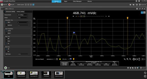
BenchVue Software (Now included)
Data capture simplified. Click. Capture. Done.
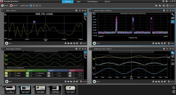
BenchVue software for the PC makes it simple to connect,
Figure 1. See your measurements across instruments in one place to
control, capture and view Keysight's DMMs simultaneously quickly correlate measurement activities and obtain actionable insights.
with other Keysight bench instruments with no additional
programming.
– Visualize multiple measurements simultaneously
– Easily log data, screen shots and system state
– Rapidly prototype custom test sequences
– Recall past state of your bench to replicate results
– Export measurement data in desired format fast
– Quickly access manuals, drivers, FAQs and videos
– Monitor and control bench from mobile devices
The Digital Multimeter App within BenchVue enables control
of digital multimeters to visualize measurements, perform
unrestricted data logging and statistical analysis.
Benefit from a new perspective by visualizing
multiple DMM’s at the same time
Display single measurements, charts, tables, or histograms from
a single instrument or multiple DMMs simultaneously to correlate
trends you might otherwise miss.
Record measurements and export results in a few
clicks
Log and export data quickly to popular tools such as Microsoft
Excel, Microsoft Word and MATLAB for documentation or further
analysis.
Access and control tests on your DMM remotely
With the companion BenchVue Mobile app, monitor and respond
to long-running tests from anywhere.
Download BenchVue software at no cost today
www.keysight.com/find/benchvue
1. One hour limit in no-cost version.
Figure 2. BenchVue enables control of your DMM to data log and
visualize measurements in a wide array of display options.
Find us at www.keysight.com Page 3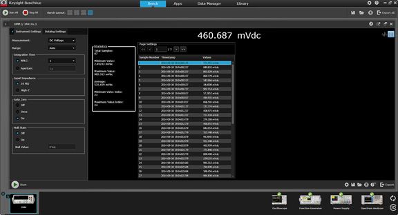
Specifications
Accuracy specifications ± (% of reading + % of range) 1
 Function                 Range 2               Test        24-hour               90 day                 1 year                 Temperature             Maximum
                                                current     23 °C ± 1 °C          23 °C ± 5 °C           23 °C ± 5 °C           coefficient             per lead
                                                                                                                                28 °C to 55 °C          resistance
 dc voltage               1.0000000 mV 3                   0.0025 + .0020      0.0040 + .0020            0.0050 + .0020         0.0004 + .0001
                          10.000000 mV 3                   0.0025 + .0020      0.0040 + .0002            0.0050 + .0003         0.0004 + .0001
                          100.00000 mV                     0.0015 + .0003      0.0030 + .0004            0.0040 + .0004         0.0004 + .00006
                          1.0000000 V                      0.0010 + .0003      0.0025 + .0004            0.0035 + .0004         0.0004 + .00004
                          10.000000 V                      0.0002 + .0001      0.0020 + .0004            0.0030 + .0004         0.0001 + .00002
                          100.00000 V 4                    0.0010 + .0004      0.0025 + .0005            0.0035 + .0005         0.0004 + .00005
 Resistance 5             1.0000000 Ω          10 mA       0.0015 + .0002      0.0050 + .0002            0.0070 + .0002         0.0005 + .00002         1Ω
                          10.000000 Ω          10 mA       0.0015 + .0002      0.0040 + .0002            0.0060 + .0002         0.0005 + .00001         1Ω
                          100.00000 Ω          10 mA       0.0015 + .0002      0.0040 + .0002            0.0060 + .0002         0.0005 + .00001         10 Ω
                          1.0000000 KΩ         1 mA        0.0015 + .0002      0.0040 + .0002            0.0060 + .0002         0.0005 + .00001         100 Ω
                          10.000000 KΩ         100 μA      0.0015 + .0002      0.0040 + .0002            0.0060 + .0002         0.0005 + .00001         1 KΩ
                          1.0000000 MΩ         10 μA       0.0015 + .0003      0.0040 + .0004            0.0060 + .0004         0.0005 + .00002         1 KΩ
                          100.00000 KΩ         5 μA        0.0020 + .0003      0.0050 + .0004            0.0070 + .0004         0.0006 + .00003         1 KΩ
 Low power                1.0000000 Ω          10 mA       0.0015 + .0002      0.0050 + .0002            0.0070 + .0002         0.0005 + .00002         1Ω
 resistance 5             10.000000 Ω          10 mA       0.0015 + .0002      0.0040 + .0002            0.0060 + .0002         0.0005 + .00001         1Ω
                          100.00000 Ω          1 mA        0.0015 + .0002      0.0040 + .0002            0.0060 + .0002         0.0005 + .00001         10 Ω
                          1.0000000 KΩ         100 μA      0.0015 + .0002      0.0040 + .0002            0.0060 + .0002         0.0005 + .00001         100 Ω
                          10.000000 KΩ         10 μA       0.0015 + .0004      0.0040 + .0004            0.0060 + .0004         0.0005 + .00001         1 KΩ
                          1.0000000 MΩ         5 μA        0.0015 + .0012      0.0040 + .0015            0.0060 + .0015         0.0005 + .00003         1 KΩ
                          100.00000 KΩ         5 μA        0.0020 + .0003      0.0050 + .0004            0.0070 + .0004         0.0006 + .00003         1 KΩ
 Voltage limited          10.000000 Ω          1 mA        0.0020 + .0002      0.0050 + .0002            0.0070 + .0002         0.0005 + .00002         1Ω
 resistance 5, 6          100.00000 Ω          100 μA      0.0025 + .0002      0.0050 + .0002            0.0070 + .0002         0.0005 + .00002         5Ω
 Channel 1 /              Ratio error in % = Channel 1 accuracy in % + Channel 2 accuracy in %
 Channel 2 (dcV
 Ratio)
 Channel                  Difference error = Channel 1 (% of reading + % of range) + Channel 2 (% of reading + % of range)
 1-Channel 2 (dcV
 difference)
 Temperature              Resolution = 0.001 °C
 SPRT 7                   SPRT probe accuracy + 0.003 °C
 RTD                      RTD probe accuracy + 0.05°C
 Thermistor               Thermistor probe accuracy + 0.1 °C
 Thermocouple 8           Thermocouple probe accuracy + 0.2 °C

1.     Specifications are for Channel 1 or Channel 2, after 2-hour warm-up, resolution at 7.5 digits (100 NPLC), with FILTERS off. RESISTANCE specifications
       are for 4-wire Ohms or 2-wire ohms using Null. Without Null, add 0.2 Ohms additional error in 2-wire Ohms function. For Analog Filter ON, add 0.002% of
       reading.
2.     20% overrange on all ranges except 5% on Voltage Limited Resistance.
3.     After using Math Null. If Null is not used add 100 nanoVolts.
4.     Channel 1 only.
5.     Channel 1 only. Resistance measurements, for NPLC < 1, add 160 μΩ rms noise.
6.     Voltage limit can be set to 20 mV (default), 100 mV, or 500 mV. Measured resistance plus Channel 1 HI and LO lead resistance is limited to 10.5 Ω on the 10 Ω
       range and 105 Ω on the 100 Ω range.
7.     For 25 Ω SPRT with triple-point of water check within the last 4 hours. Without the triple-point of water check, add 0.013 °C for 24 hours, add 0.035 °C for
       90 day, and add 0.055 °C for 1 year specifications.
8.     For fixed reference junction. Add 0.3 °C for external reference junction, add 2.0 ûC for internal reference junction.

     Find us at www.keysight.com                                                                                                                                Page 4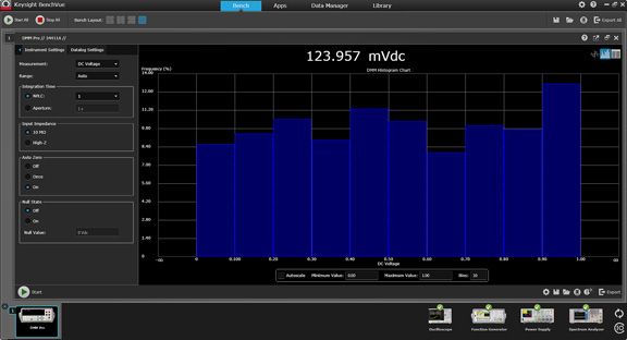
Specifications (Continued)
DC voltage noise 1
 Observational period
 Range                                      2-minute RMS noise                      2-minute peak-peak noise                24-hour peak-peak noise
 1 mV                                       1.3 nVrms                               8 nVpp                                  12 nVpp
 10 mV                                      1.5 nVrms                               10 nVpp                                 14 nVpp
 100 mV                                     10 nVrms                                65 nVpp                                 80 nVpp
 1V                                         100 nVrms                               650 nVpp                                800 nVpp
 10 V                                       450 nVrms                               3 μVpp                                  3.7 μVpp
 100 V                                      11 μVrms                                75 μVpp                                 90 μVpp

DC voltage noise vs source resistance 2
 Source resistance                          Noise                                   Analog filter                           Digital filter
 0Ω                                         1.3 nVrms                               Off                                     Med
 1000 Ω                                     1.7 nVrms                               Off                                     Med
 1 kΩ                                       4 nVrms                                 Off                                     Med
 10 kΩ                                      13 nVrms                                Off                                     Med
 100 kΩ                                     41 nVrms                                Off                                     Med
 1 MΩ                                       90 nVrms                                Off                                     Med

1.     After a 2-hour warm-up, ± 1 °C, 6.5 digits (10 PLC) with Analog Filter Off and Digital Filter Medium (50 reading average). 2-minute rms and 24-hour noise
       typical. For measurements using 0.02 or 0.2 NPLC, add 800 nV rms noise.
2.     Typical noise behavior for Ch 1 or Ch 2, after 2 hour warm-up, 6.5 digits (10 PLC), 2 minute observation period on 1 mV range. For peak-to-peak noise,
       multiply rms noise by 6.

     Find us at www.keysight.com                                                                                                                            Page 5
Measurement Characteristics
 DC voltage
 Measurement method                         Continuously integrating multi-slope III
                                            A-D Converter
 A-D linearity                              0.00008% of reading + 0.00005% of range
 Input resistance                           100 V (Ch1 only): 10 MΩ ± 1%
                                            1 mV through 10 V: > 10 GΩ, in parallel with < 3.6 nF
 Input bias current                         < 50 pA at 25 °C
 Injected current                           < 50 nA pp at 50 or 60 Hz
 Input protection                           150 V peak any input terminal to Channel 1 LO, continuous
                                            Channel-to-channel switching error (typical): 3 nV
 Channel isolation                          Isolation between input channels > 1010 Ω
 Earth isolation                            350 V peak any input terminal to earth
                                            Impedance from any input terminal to earth is > 10 GΩ and < 400 pF
 Maximum voltage                            Channel 1 LO to Channel 2 LO, 150 V peak
 Resistance
 Measurement method                         Selectable 4-wire or 2-wire ohms
                                            Current source referenced to Channel 1 LO input
 Offset compensation                        Used on all ranges except 100 kΩ and 1 MΩ
                                            Can be turned off if desired
 Protection                                 150 V peak
 Open circuit voltage                       For resistance and low power resistance
                                            < 14 V. 20 mV, 100 mV, 500 mV selectable clamp
 Temperature
 SPRT                                       ITS-90 calibrated temperature with the range of –190 °C to +660 °C
 Thermocouple                               ITS-90 conversions of Type B, E, J, K, N, R, S, T
 Thermistor                                 5 kΩ
 RTD                                        Type α =.00385 and α =.00392. R0 from 4.9 Ω to 2.1 kΩ. ITS -90 (IEC-751)
                                            Callendar Van Dusen conversion.
 Measurement noise rejection 60 (50) Hz 1
 dc CMRR                                    140 dB
 ac CMRR                                    70 dB

1.    For 1 kΩ unbalanced in LO lead.

     Find us at www.keysight.com                                                                                 Page 6
Operating Characteristics 1
Function Digits Integration time Readings/s 2
dcV thermocouple 7-1/2 200 plc .15 (.125)
7-1/2 100 plc .3 (.25)
6-1/2 20 plc .1.5 (1.25)
6-1/2 10 plc 3 (2.5)
5-1/2 1 plc 25 (20.8)
5-1/2 0.2 plc 100 (100)
4-1/2 0.02 plc 250 (250)
Resistance 7-1/2 200 plc .075 (.062)
dcV1/DCV2 7-1/2 100 plc .15 (.125)
dcV 1-2 6-1/2 20 plc .75 (.625)
RTD 6-1/2 10 plc 1.5 (1.25)
Thermistor 5-1/2 1 plc 12.5 (10.4)
0.2 plc 50 (50)
4-1/2
0.02 plc 125 (125)
1. Speeds are for delay 0, Display OFF, Filters OFF, Offset Compensation OFF.
2. Reading speeds for 60 Hz or (50 Hz), 100 mV through 100 V ranges. 1 mV range 30/s MAX, 10 mV range 170/s MAX, thermocouple 120/s MAX.
Find us at www.keysight.com Page 7Operating Characteristics 1 (Continued) Integration time Normal mode rejection 2 200 plc/3.335 s (4 s) 110 dB 3 100 plc/1.675 s (2 s) 105 dB 3 20 plc/334 ms (400 ms) 100 dB 3 10 plc/167 ms (200 ms) 95 dB 3 2 plc/33.3 ms (40 ms) 90 dB 1 plc/16.7 ms (20 ms) 60 dB < 1 plc 0 System speeds 4 Configuration rates 26/s to 50/s Autorange rate (Volts) > 30/s ASCII reading to RS-232 55/s ASCII reading to GPIB 250/s Max. internal trigger rate 250/s Max. ext. trig. rate to memory 250/s Triggering and memory Reading HOLD sensitivity 10%, 1%, 0.1%, or 0.01% of range Samples/Trigger 1 to 50,000 Trigger delay 0 to 3600 s; 10 μs step size External trigger delay < 1 ms External trigger jitter < 500 μs Memory 1024 readings Math functions NULL Channel 1 dcV, Channel 2 dcV, Difference, Resistance, Temperature STATS Min, Max, Average, Peak-Peak, Standard Deviation, Number of readings SCALE Allows linear scaling as y = mx+b CHART NULL Establishes zero for rear panel output Filter (Analog or digital or both) Analog Low pass 2 pole at 13 Hz, available for dcV on 1 mV, 10 mV, 100 mV range Digital Moving average filter, 10 (fast), 50 (medium), or 100 (slow) reading averages Chart Out (Analog out) Maximum output ± 3V Resolution 16 bits Accuracy ± 0.1% of output + 1 mV Output resistance 1 kΩ ± 5% Update rate Once per reading Span and offset Adjustable Standard programming languages SCPI (IEEE 488.2), Keithley 181 Accessories included 4 ft low thermal cable with copper spade lugs, Kelvin clip set, 4-wire shorting plug, user’s manual, service manual, test report, contact cleaner, and power cord. 1. For 1 kΩ unbalanced in LO lead. 2. For power line frequency ± - 0.1%, Filters OFF. For Digital Filter slow add 20 db, for medium or fast add 10 db for NPLC 3 1. 3. For power line frequency ± - 1%, use 80 db, for ± 3% use 60 db. 4. Speeds are for NPLC 0.02, Delay 0, Display OFF, Chart Out OFF. Find us at www.keysight.com Page 8
General Specifications
 Options                                       Description
 Front panel connection                        Shielded, low thermal, 99% copper contacts
 Power supply                                  100 V/120 V/220 V (230 V)/240 V ± 10%
 Power line frequency                          45 Hz to 66 Hz and 360 Hz to 440 Hz
                                               Automatically sensed at power-on
 Power consumption                             25 VA peak (10 W average)
 Operating environment                         Full accuracy for 0 °C to 55 °C
                                               Full accuracy to 80% RH at 40 °C (non condensing)
                                               Full accuracy to 40% RH for 41 °C to 55 °C (non-condensing)
 Storage environment                           –40 °C to 75 °C
 Size                                          254.4 mm W x 374.0 mm L x 103.6 mm H (10.02” W x 14.72” L x 4.08” H)
 Weight                                        3 kg (6.5 lbs)
 Safety                                        Designed to CSA, UL-1244, IEC-1010. RFI and ESD: CISPR 11.

Ordering Information
Includes low thermal input cable (34102A), low thermal shorting plug (34103A), Kelvin clip set (11062A), calibration certificate, power
cord. Also includes CD with: IntuiLink software, IVI and VXI PnP drivers, user’s guide, service guide, and data sheet.

 Options                                       Description
 34420A-ABA                                    English localization
 34420A-ABD                                    German localization: Translated operating manual
 34420A-ABF                                    French localization: Translated operating manual
 34420A-ABJ                                    Japanese localization: Translated operating manual
 34420A-A6J                                    ANSI Z540 compliant calibration

Accessories
 Options                                       Description
 34102A                                        Low-thermal input cable (four conductor) with copper spade lugs
 34103A                                        Low-thermal shorting plug
 34104A                                        Low-thermal input connector
 34131A                                        Transit case
 34161A                                        Accessory pouch
 34190A                                        Rackmount Kit: Designed for use with only one instrument, mounted on either the left or the right side
                                               of the rack.
 34191A                                        2U Dual Flange Kit: Secures the instrument to the front of the rack. This kit can be used with the
                                               instrument to the front of the rack.
 34194A                                        Dual Lock Link Kit: Recommended for side-by-side combinations and includes links for instruments
                                               of different depths. This kit can be used with the 34191A 2U Dual Flange Kit to mount two half-
                                               width, 2U height instruments side-by-side.

 Find us at www.keysight.com                                                                                                                   Page 9
www.axiestandard.org
AdvancedTCA® Extensions for Instrumentation and Test (AXIe) is an
open standard that extends the AdvancedTCA for general purpose
and semiconductor test. The business that became Keysight was a
founding member of the AXIe consortium. ATCA®, AdvancedTCA®,
and the ATCA logo are registered US trademarks of the PCI
Industrial Computer Manufacturers Group.
www.lxistandard.org
LAN eXtensions for Instruments puts the power of Ethernet and the
Web inside your test systems. The business that became Keysight
was a founding member of the LXI consortium.
www.pxisa.org
PCI eXtensions for Instrumentation (PXI) modular instrumentation
delivers a rugged, PC-based high-performance measurement and
automation system.
Download your next insight
Keysight software is downloadable
expertise. From first simulation through
first customer shipment, we deliver the
tools your team needs to accelerate from
data to information to actionable insight.
– Electronic design automation (EDA)
software Learn more at
– Application software www.keysight.com/find/software
– Programming environments
– Productivity software Start with a 30-day free trial.
www.keysight.com/find/free_trials
Learn more at: www.keysight.com
For more information on Keysight Technologies’ products, applications or services,
please contact your local Keysight office. The complete list is available at:
www.keysight.com/find/contactus
Find us at www.keysight.com Page 10
This information is subject to change without notice. © Keysight Technologies, 2019 - 2020, Published in USA , June 16, 2020, 5968-0161ENYou can also read