Waste-to-Energy with CCS: A pathway to carbon-negative power generation
←
→
Page content transcription
If your browser does not render page correctly, please read the page content below
1

Waste-to-Energy
with CCS: A pathway
to carbon-negative
power generation

David T. Kearns
Senior Consultant, CCS Technology
2

Introduction
A growing global population and rising living standards are producing ever greater
quantities of municipal solid waste (MSW).

It is projected that globally by 2050, 3.40 billion tonnes of waste will be generated each
year (The World Bank, 2018); a staggering 70 per cent increase from 2016 levels. Today,
most of the world’s waste is landfilled (37 per cent), dumped (33 per cent), recycled or
reused (19 per cent), or incinerated (11 per cent) (The World Bank, 2018).

Both landfilling and dumping are highly unsustainable solutions; they use large areas of
land and result in the release of significant environmental pollutants, including the
greenhouse gases carbon dioxide (CO2) and methane (CH4) as the waste decomposes and
often pose a health and safety hazard in developing countries (The World Bank, 2019).
Landfill storages near cities are coming under increased capacity pressure, resulting in
rising landfill charges by local governments.

This same growth in population and living standards is also driving ever-larger demand for
energy, especially electricity.

A key solution to these challenges of MSW disposal, rising energy demand and methane
emissions from MSW is Waste-to-Energy (WtE); the generation of energy – in the form of
electricity and heat – from the processing of waste. The addition of carbon capture and
storage (CCS) to WtE has the potential to make waste a zero or even negative emissions
energy source, depending on the ratio between biogenic and non-biogenic waste fraction.

What is Municipal Solid Waste?
Municipal Solid Waste is the solid waste material produced by households and commercial
businesses. The average global composition (by mass) of MSW is shown in Figure 1.
3

Figure 1: MSW global average composition by mass (Kaza, et al., 2018)

In lower-income countries, there tends to be a higher proportion of food and green waste,
while higher-income countries tend to have more recyclables (glass, metals, paper and
cardboard) and much more plastic. Per capita volumes of MSW also rise strongly with
income (Figure 2), so economic growth in the developing world will result in much higher
production of MSW.

Figure 2: Waste generation per capita by Income Group (Kaza, et al., 2018, p. 23)

The proportion of plastic in MSW is rising (Energy Information Administration (USA), 2007)
as kerbside recycling has reduced the recyclables content of MSW in many countries –
especially paper and cardboard.

The heterogeneous nature of MSW means that sorting is required before use in WtE
plants. Non-combustible materials and valuable substances (e.g. metals) are typically
removed using bulk sorting equipment.

The remaining materials, mostly plastics, food and green waste, as well as contaminated
paper and cardboard, are typically sent to landfill. It is these materials which are prime
candidates for WtE.

Waste-to-Energy plants
Over 2,430 WtE plants are operating globally. More than 2,700 plants with an MSW
capacity of 530 million tonnes are forecast to be operational by 2027 (Ecoprog, 2018).

Waste to Energy facilities incinerate combustible materials in MSW. Depending on the
combustibles content, incineration can reduce MSW volumes by up to 90 per cent (Perrot &
Subiantoro, 2018). This reduces pressure on landfills while providing a reliable energy
source for heat and electricity for growing cities around the world.

The energy they provide can also displace energy from conventional fossil fuel facilities,
helping abate greenhouse gas emissions.
4
Waste-to-Energy operation
A typical WtE plant consists of the following parts (Azapagic & Perdan, 2011):
• Waste handling, including waste reception and pre-treatment
• Incinerator and boiler
• Energy recovery and energy generation plant
• Air pollution control plant
• Ash treatment and removal.
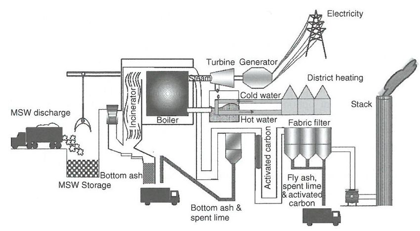
A technology overview diagram is provided in Figure 3:
Figure 3: Waste to Energy – a technology overview (Azapagic & Perdan, 2011, p. 275)
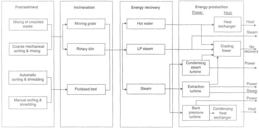
A typical representation of a WtE plant producing electricity and heat for homes is provided
in Figure 4: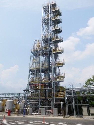
5

Figure 4: Typical Waste-to-Energy representation for heat and power production (Azapagic & Perdan, 2011)

Waste handling and pre-treatment
A combination of manual and automated processes are used to separate MSW into
components, including pneumatic, magnetic and sieving operations. Large objects are
removed, and the separation equipment produces a range of streams for composting,
recycling and fuel.

Generally, waste is suitable for combustion without additional fuel when it contains 25 per cent carbon and has
6

Figure 5: Carbon balance for 1000 tonnes of MSW

If a capture project captures more than the non-biogenic fraction of its CO2 emissions, it
can allow a facility to become a net-negative CO2 emitter.

MSW landfilling is also a major source of methane emissions in the form of landfill gas.
Methane is 25 times as potent a greenhouse gas as CO2. WtE plants avoid the formation of
landfill gas by incinerating the organic methane-producing compounds in MSW and can,
therefore, improve the net emissions savings available.

There is increasing urgency to reduce and eliminate emissions of greenhouse gases
(including CO2) from human activities. Local and National policies, as well as the global
Paris Agreement, will ensure there is increasing pressure to reduce emissions, including
from WtE plants.

The only way to eliminate net CO2 emissions from the waste-to-energy industry is carbon
capture and storage (CCS). For WtE plants operating on MSW with a significant biogenic
component, CCS provides a pathway to negative CO2 emissions while producing the power
and handling the waste produced by our growing populations and economies.
7
Waste-to-Energy + CCS
Flue gases produced by WtE plants are similar to those produced by coal-fired power
plants (refer to Table 1).
Gas species Waste incineration flue gas Pulverised coal flue gas
O2 (vol %) 7 - 14 ~6
N2 (vol %) Balance ~ 76
CO2 (vol %) 6 - 12 ~ 11
H2O (vol %) 10 - 18 ~6
NOx (ppmw) 200 - 500 500 - 800
Table 1: Typical flue gas compositions for Waste to Energy and Pulverised coal flue gases (Zevenhoven & Kilpinen, 2002)
CO2 capture for a waste to energy plant is simpler than for a coal-fired power station. MSW
contains much less sulphur and produces less particulates than coal, which means less
capital investment is required for gas cleaning.
CO2 concentrations are variable for WtE, depending on the specific materials present in the
MSW being combusted. Concentrations are in the range best suited for capture with amine-
based absorption plants.
Current developments in solvent innovation, process integration and intensification could
potentially lower the CO2 capture cost to USD 35-50 per tonne CO2 in power generation
applications.
Waste to Energy plants operate at a smaller scale than conventional coal or gas-fired
power stations, so their CO2 capture volumes are also smaller. Successful CCS
installations will need to be able to deliver low-cost abatement without the economies of
scale available at larger power plants.
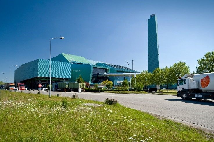
Twence Waste to Energy plant – Netherlands
The Twence WtE plant is a facility which has operated since 1986 in Hengelo, The
Netherlands. Every year the facility processes over 830,000 tonnes of waste, generating
405000 MWh of electricity and 1.5 million GJ of thermal energy for district heating.
Aker Solutions recently signed an
agreement to deliver a carbon
capture and liquefaction plant at
the Twence facility (Doyle, 2019).
The capture plant is centred on
Aker’s “Just Catch” modular
carbon capture system, designed
around simplicity, ease of
installation, rapid deployment and
low capture costs. The use of
standardised plant drawings, plant
layout, containers and foundations
greatly simplifies the engineering
complexity and cost compared to
Figure 6: Twence WtE Plant, Netherlands (image: twence.nl)
a conventional capture project.
The use of modular designs enables flexible applications and offers the cost savings of
larger-scale manufacturing of carbon capture system components. Some capture system8
components are provided in standard shipping containers; a low-cost method of system
delivery and packaging.
The capture system will have a CO2 capture capacity of 100,000 tonnes per year by 2021
(Aker Solutions, 2019). Liquefied CO2 will be sold to customers by tanker for use in
greenhouses and industrial applications.
Klemetsrud, Norway
The Klemetsrud Waste-to-Energy facility in Oslo, Norway is a three-train facility processing
over 400,000 tonnes of non-recyclable MSW. It can generate 55 MW of heat for 40,000
homes and 10.5 MW of electricity.
Following a successful 2011 pilot project
to capture 90 per cent of the CO2 from a
small flue gas stream, a full-scale carbon
capture project is now under
development.
The project will capture 400,000 tonnes
of CO2 every year with an amine-based
absorption capture plant. Although this is
an early example of large-scale capture
from Waste-to-Energy, the capture
Figure 7: Klemetsrud Waste-to-Energy plant in Oslo, Norway process is well understood and tested in
(image: thechemicalengineer.com)
other capture applications. As Waste-to-
Energy flue gas is comparable to that from power station, captured emissions will be
transported by ship for storage. Fifty per cent of the captured CO2 is biogenic, making this a
partial bio-energy with carbon capture and storage (BECCS) facility; a CO2-negative
project.
Saga City, Japan
Saga City in Saga Prefecture, Japan, is the home
of an MSW waste-to-energy plant. Since 2016, a
Toshiba-designed CO2 capture plant has
operated at this site (Figure 8) capturing 10
tonnes/day for use in the local agricultural sector.
This is producing economic value from CO2
which would otherwise have been vented to the
atmosphere.
Figure 8: Carbon capture plant at Saga City WtE plant,
Japan (image supplied)9
Towards zero waste and negative carbon emissions
One key advantage of waste-to-energy plants is not just in providing “low-carbon” energy
and zero waste, but its potential “negative carbon” contribution towards climate change
mitigation targets.
Using CCS in the waste-to-energy industry presents a particular opportunity for bioenergy
with carbon capture and storage (BECCS); one of the few abatement technologies that can
be carbon negative. BECCS involves the utilisation of biomass as an energy source and the
capture and permanent storage of the CO2 produced.
The Intergovernmental Panel on Climate Change (IPCC) SR15 report (2018, p. 34)
acknowledges that Carbon Dioxide Removal (CDR), including BECCS, is necessary to limit
warming to 1.5°C:
“All analysed pathways limiting warming to 1.5°C with no or limited
overshoot use CDR to some extent to neutralize emissions from sources
for which no mitigation measures have been identified and, in most cases,
also to achieve net negative emissions to return global warming to 1.5°C”.
Conclusion
The rapid growth of municipal solid waste production and living standards will continue to
increase the quantities of MSW production around the world. The conventional option of
landfilling is environmentally unsustainable and becoming uneconomic. Demand for more
energy and reduced landfilling volumes is encouraging continued growth in WtE plants.
If the world is to keep on track with its emissions reduction targets under the Paris
agreement, it is vital that the WtE sector manages its CO2 emissions.
The continued growth of MSW generation and the need for scalable negative-emissions
energy options will only increase the opportunities for CCS in the WtE sector.
Further information:
For more details of next-generation capture technology and process modification paths,
please contact the Global CCS Institute.10 References Aker Solutions, 2019. Aker Solutions Signs Carbon Capture Contract With Twence in the Netherlands. [Online] Available at: https://akersolutions.com/news/news-archive/2019/aker-solutions-signs- carbon-capture-contract-with-twence-in-the-netherlands/ Azapagic, A. & Perdan, S., 2011. Sustainable Development in Practice: Case Studies for Engineers and Scientists. 2nd ed. Chichester, West Sussex, United Kingdom: Wiley- Blackwell. Doyle, A., 2019. Aker Solutions to provide carbon capture technology to waste-to-energy plant, s.l.: The Chemical Engineer. Ecoprog, 2018. Waste to Energy 2018/2019: Technologies, plants, projects, players and backgrounds of the global thermal waste treatment business, Cologne, Germany: Ecoprog. Energy Information Administration (USA), 2007. Methodology for Allocating Municipal Solid Waste, Washington, DC, USA: US Department of Energy. Intergovernmental Panel on Climate Change, 2018. Global warming of 1.5°C, s.l.: Intergovernmental Panel on Climate Change. NOAA, 2018. Global Greenhouse Gas Reference Network. [Online] Available at: https://www.esrl.noaa.gov/gmd/ccgg/trends/full.html [Accessed January 2018]. Perrot, J.-F. & Subiantoro, A., 2018. Municipal Waste Management Strategy Review and Waste-to-Energy Potentials in New Zealand. Sustainability, Volume 10. The World Bank, 2018. What a Waste 2.0: A Global Snapshot of Solid Waste Management to 2050, Washington, DC, USA: World Bank Group. The World Bank, 2019. Solid Waste Management [Online] Available at: https://www.worldbank.org/en/topic/urbandevelopment/brief/solid-waste-management Zevenhoven, R. & Kilpinen, P., 2002. Control of pollutants in flue gases and fuel gases, Espoo/Turku, Finland: Helsinki University of Technology.
11
You can also read