A Comparison of Resistive Terminators for High Speed Digital Data Transmission
←
→
Page content transcription
If your browser does not render page correctly, please read the page content below
High Frequency Design                                           From October 2005 High Frequency Electronics
                                                                         Copyright © 2005 Summit Technical Media
        RESISTIVE TERMINATORS

                      A Comparison of Resistive
                      Terminators for High Speed
                      Digital Data Transmission
                      By Jerry Seams
                      IRC Advanced Film Division, TT electronics

                                           M
                                                     ulti-gigabit per    quency is the frequency above which harmon-
             The time and frequency                  second      data    ics present in the pulse edge may be ignored.
          response of a resistive ter-               rates are now       The faster the rise time, the higher the knee
         minator is a key parameter         commonplace in the           frequency and the more important high quali-
          when selecting the proper         worlds of telecommunica-     ty terminators become. Digital drivers and
        termination method for high         tions, computing and         SERDES (serializer/deserializer) chips with
            speed digital signal lines      data networking. With        sub-100 ps rise times are widely available
                                            digital data rates reach-    today. By equation (1), the equivalent sine
                      ing beyond 1-Gbit/s, digital designers are now     wave frequency of the rising edges of this data
                      wrestling with a new list of design problems       stream is approximately 5 GHz.
                      such as transmission line reflections and sig-
                      nal distortion due to poorly chosen transmis-
                                                                                       0 .5
                      sion line terminators.                                 fknee =                                  (1)
                                                                                        tr
                          By properly choosing a termination match-
                      ing the characteristic impedance (Z0) of the
                      transmission line, the energy in a digital             At gigabit per second data rates, the high
                      transmission line signal can be absorbed and       frequency characteristics of the terminating
                      turned into heat instead of being reflected and    resistor or resistor network must be taken
                      interfering with other forward propagating         into consideration to avoid the glitch-causing
                      signals. Care must be taken, however, when         effects of signal distortion due to a poorly
                      choosing a resistor for high speed transmis-       selected terminator. This paper compares the
                      sion line termination—not just any resistor        high speed performance of popular resistor
                      from the top desk drawer will do. A terminat-      technologies and packages used as high speed
                      ing resistor that matches at low frequencies       terminators.
                      may not remain a match at high frequencies.
                      Lead and bond wire inductance, parasitic           Background
                      capacitance and skin effect can drastically            In the past, digital design ignored the
                      change the impedance of a terminator at high       transmission line effects of logic interconnec-
                      frequencies. This change in impedance, and         tions. Generally, as long as the round trip
                      the resulting signal distortion, can cause false   propagation delay of a signal trace or cable
                      triggering, stair stepping, ringing, overshoot,    was small as compared to the rise time of the
                      delays and loss of noise margin in high speed      digital signal, the reflections generated on the
                      digital circuits [3].                              line were ignored and not terminated [1]. The
                          The rise time of the digital signals           length of the transmission path was assumed
                      required to transmit data at multi-gigabit         to be infinitely short. No reflections can occur
                      rates is now under 100 ps. The equivalent sine     on an infinitely short line since there is no
                      wave frequency of a digital signal (fknee, the     propagation time between a signal and its
                      knee frequency) can be approximated by             reflection from the end of the line. A transmis-
                      dividing 0.5 by the rise time [1]. The knee fre-   sion line can be considered to be “short” if its

18   High Frequency Electronics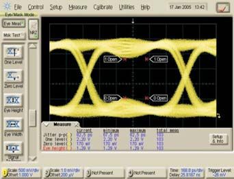
High Frequency Design
RESISTIVE TERMINATORS
(a) (b)
(c) (d)
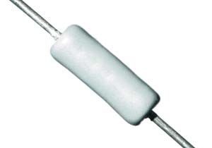
Figure 1 · Maximum physical lengths of unterminated Figure 2 · Tested terminators. (a) Axial leaded resistor.
transmission lines. (b) 0603 chip. (c) QSOP. (d) BGA.
electrical length (lelectrical) is less than 1/6 of the rise time culated from equation (4):
(Trise) of the digital signal [1, 3]. Thus, the line is short if:
0 .1 m
lelectrical = = 613 ps (6)
lelectrical
T
≤ rise (2) 163 × 106 m/s
6
in electrical length.
The speed at which signals propagate along a trans- In the case of a digital signal with a 100 ps rise time
mission line (vp) can be calculated by dividing the speed (Trise), equation (2) yields:
of light (c) by the square root of the effective dielectric
constant (εeff) of the dielectric material used in the trans-
lphysical
mission line [2]: lelectrical = (7)
vp
c
vp = (3) Since the electrical length of the line, (lelectrical) is
ε eff greater than 1/6 of the rise time of the signal, the line
should be terminated. Using the 1/6 rise time rule, Figure
Then, to calculate the electrical length of a transmis- 1 shows the maximum length microstrip transmission
sion line (lelectrical), divide the physical length of the trans- line that could remain unterminated for both FR-4 and
mission line (lphysical) by the propagation velocity (vp): high purity alumina substrates.
Back in the days of 10 ns rise times, digital designers
could generally ignore reflections on transmission lines of
lphysical
lelectrical = (4) up to 0.25 meters in physical length. Today’s 100 ps rise
vp times require more circuit board traces to be considered
for reflections according to the above rule of thumb. Using
Example: 1/6 of the electrical length of a 100 ps rise time requires
Consider a 10 cm long transmission line using that lines physically longer than about 3 mm be termi-
microstrip construction on 0.062" thick FR-4 board mate- nated in order to prevent reflections from inducing signal
rial. The 0.062" thick, FR-4, 50-ohm microstrip has an integrity problems [2]. Nearly all circuit board traces are
effective dielectric constant (εeff) of about 3.4. Calculating treated as terminated transmission lines in high speed
the propagation velocity (vp) from equation (3): design today.
Selection and Testing of Resistive Terminators
3 × 10⁸ m/s
vp = = 163 × 106 m/s (5) The selection of resistive terminations is crucial to the
3 .4 signal integrity of high speed digital design. A resistive
terminator is, often erroneously, considered to be a
The electrical length (lelectrical) of this line is then cal- lumped element with no reactive properties. But in real
20 High Frequency Electronics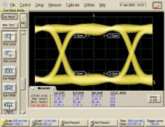
High Frequency Design
RESISTIVE TERMINATORS
(a) (b) (c)
(d) (e)
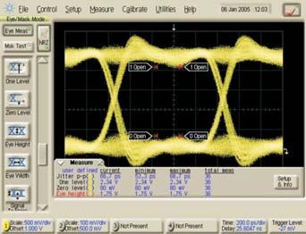
Figure 3 · 1 Gbit/s eye diagram displays of signals terminated by: (a) reference resistor; (b) axial leaded RN55;
(c) 0603 chip; (d) QSOP; (e) BGA.
designs, parasitic capacitance and inductance existing in Device Eye Closure (%) Overshoot (%)
terminators can kill an otherwise well thought out high
speed design. Reference 16 7
This note compares the performance of four different Axial Discrete 23 24
types of thin film resistors in high speed digital termina- 0603 Chip Discrete 23 9
tor applications: an axial leaded RN55 size discrete, an QSOP Array 36 10
0603 size discrete chip, a QSOP array, and a BGA array. BGA Array 20 4
Data is presented in the time domain since this is the pre-
ferred domain for most high speed digital design efforts Figure 4 · Eye diagram measurement summary.
[4]. All resistors are 50 ohms at DC nominal except for the
QSOP array which is 47 ohms DC nominal resistance.
The axial discrete is an IRC model BR5, the 0603 chip closure and slightly better than the reference in terms of
is IRC model PFC-W0603HF, the QSOP is IRC model overshoot. The axial discrete and the QSOP array show
GUS-QSCA, and the BGA is IRC model CHC-CC0910B. the worst performance with eye closure of 23% and 36%
The devices tested are shown in Figure 2 using an Agilent respectively and overshoot of 24% and 10% respectively.
Infiniium DCA 86100A oscilloscope with 54754A plug-in The impedance response of the reference resistor and
and Agilent 54701A 2.5 GHz probes in conjunction with a each of the DUTs to a 100 ps rise time pulse are shown in
Tektronix DG2040 differential data generator at 1 Gbit/s. Figures 5a through 5e using an Agilent Technologies 8753
Eye diagrams for each of the DUTs are shown in Figure vector network analyzer swept to 6 GHz and then con-
3. In addition, a thin film microwave calibration reference verting to time domain using Agilent Advanced Design
resistor was measured for comparison to the DUTs. System Software (ADS).
Eye diagrams at a signaling rate of 1 Gbit/s for the ref- Again, the BGA is the best performer with only 2 ohms
erence resistor and DUTs are shown in Figures 3a change in impedance due to the 100 ps rising edge and is
through 3e. A summary of the eye diagram measurements nearly as good as the reference resistor. The axial leaded
is shown in Figure 4. The BGA array shows the best per- resistor is the worst performer, changing from 50 ohms to
formance—nearly as good as the reference in terms of eye 135 ohms in impedance due to the 100 ps rise time pulse.
22 High Frequency Electronics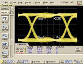
High Frequency Design
           RESISTIVE TERMINATORS

     (a)                                  (b)                                      (c)

                     (d)                                        (e)
Figure 5 · Impedance reponses of: (a) reference resistor; (b) axial leaded RN55; (c) 0603 chip; (d) QSOP; (e) BGA.

Using equation (8) the amount of reflection (Γ) present at
                                                              Device                Max. Impedance Reflection (%)
the terminator due to impedance mismatch with the
                                                                                    Change (ohms)
transmission line at the pulse edge can be found:
                                                              Reference                      1                 1
           Z − Z0                                             Axial Discrete                85                46
     Γ=                                                (8)    0603 Chip Discrete            11                10
           Z + Z0
                                                              QSOP Array                    19                16
                                                              BGA Array                      2                 2
where Z = the maximum impedance of the DUT and Z0
= the characteristic impedance of the transmission line.     Figure 6 · Time Domain Impedance Summary.
Figure 6 shows the impedance summary for the refer-
ence resistor and the 4 DUTs. The summary shows that
the axial discrete terminator reflects 46% of the signal     present reality at high frequencies and fast rise times.
back to the source during the pulse edge while the BGA          In the high frequency lumped element models for the
reflects less than 2% of the signal back to the source.      PFC-W0603HF-xx-50R0-x and the CHC-CC0910B-xx-
The larger the reflected energy, the more likely that the    50R0-x, shown in Figure 7, the reactive properties of the
forward travelling wave will be distorted by the relec-      terminators are evident in the small, but still present par-
tion.                                                        asitic capacitances and inductances in the components.
                                                             Both models are valid for rise times to 100 ps.
Conclusions and Recommendations                                 Eye diagram and impedance profile time domain data
   A well matched termination resistor at all frequencies    provide a good comparison of the performance of four
below the knee frequency (fknee) is essential for the pre-   types of resistive terminators commonly used to termi-
vention and suppression of bit error inducing signal dis-    nate transmission lines. A high frequency resistive refer-
tortion in high speed digital circuits. While it may be      ence provides a bench mark against which the four dif-
tempting to assume that resistive terminators are ideal      ferent terminators may be compared. In terms of the
lumped elements—they are not. They possess induc-            maintenance of signal integrity as defined by eye closure,
tances and capacitances which are an unintended but          overshoot, impedance change and percent reflection the

24    High Frequency Electronics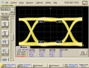
High Frequency Design
           RESISTIVE TERMINATORS

     (a)                                          (b)

Figure 7 · Lumped element models: (a) PFC-W0603HF-xx-50R0-x; (b) CHC-CC0910B-xx-50R0-x.

terminators are ranked from best to worst as follows:           4. G. Moretti, “Tight Squeeze: RF Design,” EDN,
                                                              November 27, 2003.
1. BGA packaged array
2. 0603 Chip                                                  Author Information
3. Wire bonded QSOP array                                        Jerry Seams is the Manager of New Business
4. Axial leaded discrete                                      Development for the IRC Advanced Film Division of TT
                                                              electronics, Corpus Christi, Texas. His current duties
   Intuitively, this makes sense. The axial discrete and      include new product development, technical marketing
the QSOP both possess unwanted inductance due to leads        and worldwide responsibility for thin film product train-
and bond wires which do not exist in the chip or the BGA.     ing and technical customer support. Prior to his current
Both unwanted capacitance and unwanted inductance             position, Jerry worked as Applications Manager, Process
are minimized in the BGA with its downward facing “flip       Engineering Manager, and Applications Engineer as well
chip” configuration and short conductor to resistor traces.   as Electronic Systems Designer for TRW, Inc. He received
This results in performance nearly as good as the high        his Bachelor of Science degree from Texas Tech
frequency reference resistor.                                 University, Lubbock, Texas and his Master of Science in
                                                              Electrical Engineering from Texas A&M University,
Notes                                                         Kingsville, Texas.
    1. The effective dielectric constant applies to quasi-
TEM mode transmission lines such as microstrip. The
effective dielectric constant of a quasi-TEM mode line can           Writing for High Frequency Electronics
be determined by formulae from electromagnetic texts or
from software calculators such as Agilent Technologies'         We have very simple guidelines for authors wishing
AppCad. In true TEM mode transmission lines such as             to submit an article for publication in High
coaxial cables the effective dielectric constant equals the     Frequency Electronics:
relative dielectric constant [2].
    2. Assumes microstrip design on FR-4 dielectric, εr =       1. Prepare a description of the article—this can be
4.6 and Z0 = 50 ohms, resulting in a velocity of propaga-       an abstract, outline, informal description, a draft
tion of 165 m/s.                                                manuscript or even the finished piece.

References                                                      2. Send the above description to Editorial Director
   1. H. Johnson and M. Graham, High-Speed Digital              Gary Breed—e-mail gary@highfrequencyelectron-
Design, Upper Saddle River, NJ: Prentice Hall, pp. 2, 166-      ics.com or post to: High Frequency Electronics, 403
167.                                                            Venture Ct. #7, Verona, WI 53593.
   2. K. Demarest, Engineering Electromagnetics, Upper
Saddle River, NJ: Prentice Hall, pp. 350, 645, 648.             We will review the proposed article and follow up
   3. B. Caldwell and D. Getty, “Coping with SCSI at            with an expected publishing schedule, suggestions
Gigahertz Speeds,” EDN, July 6, 2000, pp. 94, 96.               for improvement, or other feedback.

26    High Frequency Electronics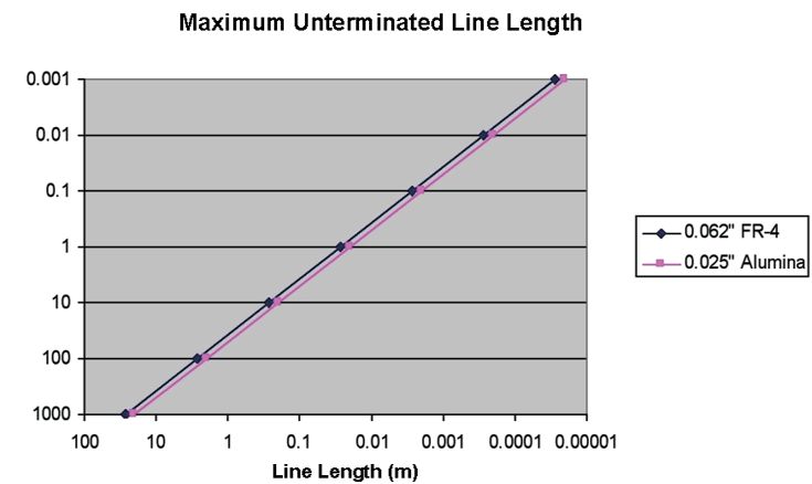
You can also read