What's New? - OPEN MIND ...
←
→
Page content transcription
If your browser does not render page correctly, please read the page content below
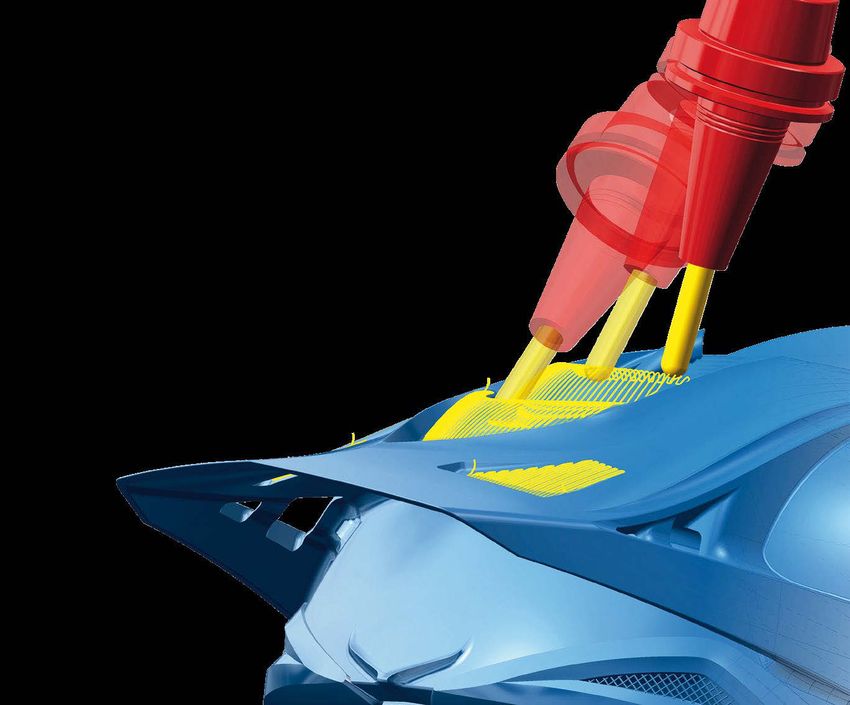
© The helmet was programmed and produced by DAISHIN.

What’s New?
What’s New in 2021.2?
                                                          Programming with hyperMILL 2021.2 is getting faster, and the software has
                                                                                                 ®

                                                          also become more user-friendly. One example of this is the convenient and
                                                          secure display of the referenced geometry data in the individual strategies.
                                                          Important enhancements, such as “High precision surface mode” and
                                                          “Smooth overlap,” ensure an even more versatile application of our 3-axis
                                                          and 5-axis strategies. Thanks to the BEST FIT highlight, hyperMILL enables
                                                                                                                                                  ®

                                                          component alignment at the touch of a button. A new method guarantees
                                                          highly efficient and safe movements for machining centers with a machine
                                                          tunnel, and hyperCAD -S also offers new functions for electrode production.
                                                                                       ®

Contents
General                                                                           CAM – ADDITIVE Manufacturing
Highlight Advanced visualization options                              3           Highlight Weave mode                                                  9
Advanced report output                                                3           Tilt strategy: Rigid guiding                                          9
Tool database: “Allow plunge”                                         4
Edit toolpath                                                         4           hyperMILL® BEST FIT
Macro database                                                        4           Highlight BEST FIT component alignment                               10

CAM – 2.5D Strategies                                                             CAD Integration: hyperCAD®-S
T-Slot Milling on 3D Model                                            5           Highlight New import formats                                         13
                                                                                  Data import with templates                                           13
CAM – 3D Strategies                                                               Mating                                                               13
3D Iso Machining                                                      5           Shapes – rotation                                                    13
3D Equidistant Finishing                                              5           Drafting with V-sketch                                               14
Highlight 3D Z-level Shape Finishing                                  6           Shape contour                                                        14
                                                                                  Average curve                                                        14
CAM – 5-axis Strategies
5-axis Equidistant Finishing                                          6           hyperCAD®-S Electrode
5-axis Tube Machining                                                 7           Create electrode                                                     15
                                                                                  Highlight hyperCAD®-S Electrode Converter                            15
CAM – VIRTUAL Machining
Individual origin output                                              8
 Highlight Optimizer: G1 movement optimization                        8                    QR codes are clickable
 Highlight Optimized tunnel logic                                     8

Review system compatibility: To ensure optimal performance and stability, we recommend regularly running our diagnostic program, Systemchecktool.exe.
Note: Windows 10 may reset the graphics driver or its settings when carrying out updates. System requirements: Windows 10 (64 bit) | CAD Integrations:
               ®                                                                                                          ®

hyperCAD -S, Autodesk Inventor , SOLIDWORKS, ThinkDesign 64 bit | Software languages: de, en, es, fr, it, nl, cs, pl, ru, sl, tr, pt-br, ja, ko, zh-cn, zh-tw
          ®            ®         ®
General

Highlight
Advanced visualization options
New functions in hyperMILL® ensure a better overview during
CAM programming.

n Automatic stock display
The stock can now be displayed automatically for any machin-
ing job. This means that, if required, the used stock can become
immediately visible when a job is selected. This visualization op-
tion can be activated or deactivated at any time in the shortcut
menu or by double-clicking the light bulb symbol.

n Preview of selected entities
The entities used in a job, such as curves, faces, or points, are
highlighted in hyperMILL® when this job is selected. The visual-
ization option can be activated or deactivated at any time using
the “Q” shortcut.
Info: The preview of selected entities is only available in hyperCAD®-S.

Benefit: Improved clarity.

Advanced report output
When creating reports, several report variants can now also be
generated in parallel. For example, a special tool report for tool
provision and a general job report for the machine operator can
be created at the same time.

In addition, reports for turning tools can now be created in the
hyperMILL® AUTOMATION Center.

Benefit: Improved user-friendliness.

                                                                               3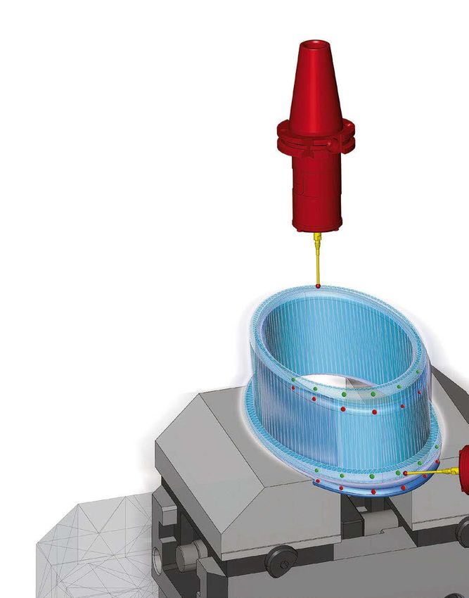
General

          Tool database: “Allow plunge”
          In the tool database, the “Allow plunge” checkbox can now be
          used for the Chamfer Cutter tool type to specify whether the tool
          is able to plunge into the material. The tool properties are taken
          into account during the collision check in the simulation. For ex-
          ample, a collision message would appear if the upstream drilling
          operation was not carried out correctly and the “Allow plunge”
          checkbox was deactivated.

          Benefit: Increased collision safety.

          Edit toolpath
          In the new version of hyperMILL®, the interactive toolpath editing
          method is now also available for 5-axis strategies. This allows
          the user to edit existing toolpaths very flexibly and adapt them
          optimally to the component conditions. The intuitive operation
          makes it easy to trim the toolpath, for example, at selected
          points and curves, in a specific area, or on a plane. Complete
          toolpath sequences between two G0 movements can also be se-
          lected and removed. Approach and retract macros allow clean
          machining of the trimmed areas. The modified toolpaths are
          checked for collisions.

          In addition, the “Edit toolpath” command can now be called di-
          rectly via the context menu of the toolpaths.

          Benefit: Flexible machining of toolpaths.

          Macro database
          Frames can now also be saved in a job macro in the macro data-
          base. To apply a macro later, the required frames must be created
          in hyperMILL® in advance.

          Benefit: Improved user-friendliness.

  4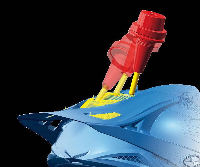
CAM – 2.5D Strategies

T-Slot Milling on 3D Model
The Woodruff cutter type can now also be used in the strategy.
The tool geometry is fully mapped in hyperMILL®, and is used for
both calculation and simulation.

Benefit: Additional cutter type.

                                       CAM – 3D Strategies

3D ISO Machining
Multiple bounding curves can now be used in the strategy to allow
different areas to be machined in one job. Several closed bound-
ing curves can be selected to precisely limit the machining.

Benefit: Improved user-friendliness.

3D Equidistant Finishing
The milling area can now additionally be defined by selecting
bounding curves. This allows targeted machining of individual
areas on a surface model.

The “Smooth overlap” option can be used to achieve clean tran-
sitions and a seamless appearance. This generates an overlap at
the bounding curves and enables a milling pattern without any
noticeable transitions.

Benefit: Improved user-friendliness and increased machining
quality.

                                                                    5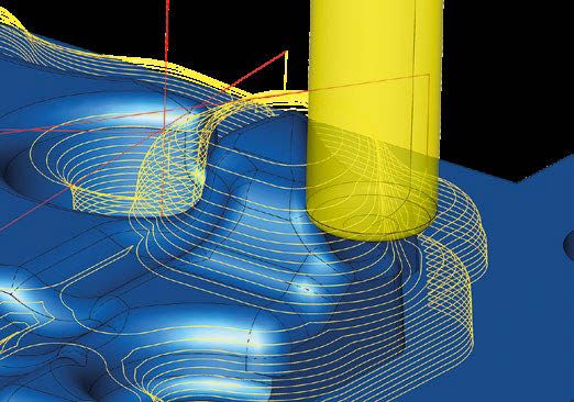
CAM – 3D Strategies

                                          Highlight
                                          3D Z-level Shape Finishing
                                          Several innovations help to improve machining.

                                          n Optimized sorting of toolpaths
                                           The reduced number of retractions ensures more homogeneous
                                           toolpaths

                                          n Smooth overlap at boundary
                                           The toolpaths overlap beyond the boundary, allowing transi-
                                           tion-free machining

                                          n Free tool geometry
                                           A free tool geometry can now be used for the calculation and
      Machining with free tool geometry    simulation of the toolpaths

                                          n Trim toolpath to stock
                                           This option allows toolpaths to now be trimmed to the stock,
                                           and unnecessary toolpaths are avoided

                                          Benefit: Increased machining quality.

CAM – 5-axis Strategies

                                          5-axis Equidistant Finishing
                                          As with 3-axis machining, the milling area can now additionally
                                          be defined for the 5-axis strategy by selecting bounding curves.
                                          This allows targeted machining of individual areas on a surface
                                          model.

                                          Benefit: Improved user-friendliness.

  6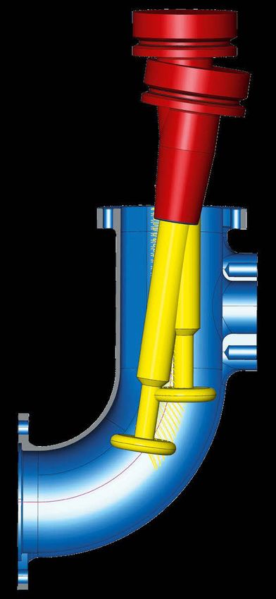
CAM – 5-axis Strategies

5-axis Tube Machining
The strategies for tube machining have been improved. To ensure
greater clarity, the 5-axis tab has been standardized and now of-
fers the same setting parameters for all strategies.

The fixed tool angle no longer needs to be activated via a checkbox,
as alternative options are now available:

n “Fixed 3D” creates toolpaths with the tool axis in the direction
  of the Z axis of the frame
n “5-axis-simultaneous” is possible in conjunction with a desired
  tilt angle and a maximum tilt angle

In 5-axis simultaneous machining, a desired tilt angle of zero de-
grees results in modified machining behavior. If collision avoid-
ance is deactivated, indexed machining is carried out exclusively
from the start point to the end point. If collision avoidance is acti-
vated, indexed machining starts and machining continues simul-
taneously when collision avoidance is necessary. When tubes are
initially vertical, unnecessary movements of the rotary axes are
avoided in this way.

When a ball mill is used with tool check switched off, the famil-
iar axial retract movement now no longer takes place. In order to
achieve a collision-free G1 movement of the tool tip (sphere) out
of the component, the retraction to the start plane is now similar
to that of a lollipop cutter.

Benefit: Optimized machining and improved setting options.

                                                                         7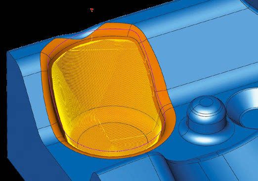
CAM – VIRTUAL Machining

                           Individual origin output
                           It is now possible to define a user-specific origin in the job list for
                           output in the NC program. For this purpose, when the “Origin ID”
                           checkbox is selected, an origin can be selected from a list or a
                           free origin parameter, such as G56, can be entered. This makes it
                           easier to work in parallel on multiple projects or also with several
                           programmers when using a virtual machine.

                           Benefit: Work more flexibly with origins.

                           Highlight

                           Optimizer: G1 movement optimization
                           The Optimizer detects violations of the axis limitations and then
                           optimizes the movement sequences. To do this, it can break G1
                           toolpaths, find a new solution within the axis limits, and con-
                           tinue machining. Here, the approach and retract movements are
                           smoothly linked to the toolpaths and are collision-checked. The
                           function automatically optimizes the NC programs, and ensures
                           that there is not an axis overtravel.

                           Benefit: Simplified programming through automatic solution
      Axis traverse path   generation and increased process reliability.

                           Highlight

                           Optimized tunnel logic
                           On machines where the tool can be retracted into a tunnel, there
                           is now the option of using a special approach and retract strate-
                           gy. In the job list, the “Optimized tunnel logic” option is selected
                           under NC safety. To join movements with safety logic, the tool is
                           retracted into the machine tunnel and the workpiece is reposi-
                           tioned over four axes.

                           Benefit: More efficient machining.

  8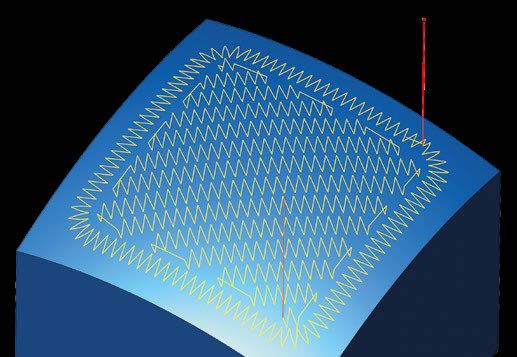
ADDITIVE Manufacturing

Highlight
Weave mode
To apply material to contours or fill areas, there is now the
“Weave” mode that can be used to generate a toolpath in a wave-
shaped or zigzag movement. This allows the application area to
be widened and the application thickness to be increased for the
individual application movement. The continuous application
also improves the metallurgical properties of the added mate-
rial. This option can be used for 2D, 3D, and 5-axis deposition.

Benefit: More efficient deposition and improved process and
material properties.

Tilt strategy: Rigid guiding
The “Rigid guiding” option can now be selected for the “Previ-
ous path” option under the tilt strategies in the 5-axis control.
The strategy thus forces an inclination with the tool vector of the
previous path, and smoothing of the tool vector is avoided for
components with sharp corners.

Benefit: Improved tool orientation and additive deposition.

                                                                      9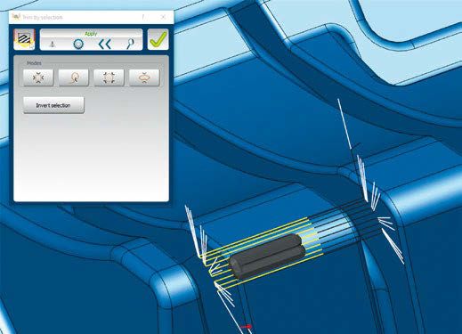
hyperMILL® BEST FIT

      Highlight

      hyperMILL® BEST FIT – Intelligent Component
      Alignment at the Touch of a Button

      Are you familiar with the problem? You spend a lot of time, effort, and patience aligning your stock or component on the
      machine, and, in the end, your finished component does not fit despite the care you have taken. We now have a simple
      and efficient solution for precisely this problem!

      Thanks to hyperMILL BEST FIT, the uncertainties relating to this critical interface are eliminated at the touch of a button.
                                ®

      You will have no more surprises, such as unmachined areas with small allowances, when you open the machine doors
      after machining. With hyperMILL BEST FIT, the process is safe, precise, and plannable.
                                            ®

      Real-time alignment in CAM
      The unaligned component is probed on the machine using 3D
      probing, and these probing points are sent back to the CAM in
      the form of a measuring report. hyperMILL® BEST FIT then adjusts
      the NC code exactly to the actual component position. So the
      virtual world (programming) is adapted to the real world (clamp-
      ing), and not the other way around!

      Features
      n Fast   and reliable component alignment in CAM in real time
      n Simulation   of the actual component position in the virtual machine
      n NC   output on actual component position
      n Real
            axis limitations and collisions are simulated
        and compensated for if necessary

 10
hyperMILL® BEST FIT
Cast components/welded components Imprecise stock Second mounting/repair
Additive components Forged components Second mounting/repair
Advantages
n Safe machining
n No more complex set-ups/special measuring equipment necessary
n Plannable setup times and processes
n Shorter processing times
n Set-up skills no longer required
n Reduced design effort ➜ No auxiliary geometry required
n No adjustment to the controller
n Easy to change machining to another device
11hyperMILL® VIRTUAL Machining – Safety first! Start the future now, and take your production to the next level! With hyperMILL® VIRTUAL Machining, OPEN MIND has realized its vision of a perfect synthesis of the virtual and real world: a new dimension of post- processors and a simulation technology for the production of tomorrow.
CAD Integration: hyperCAD -S ®
Highlight
New import formats
The new hyperCAD®-S version offers three additional formats for
file imports. SAT as standard ACIS text and OBJ and 3MF for im-
porting mesh data. These file types can therefore be imported
directly into hyperCAD®-S.
Benefit: More flexibility when importing data.
Mating
The new “Tangency” constraint allows cylindrical faces to now be
aligned tangentially to each other.
Benefit: Alignment of cylindrical faces for clamping.
Data import with templates
A template file can now be used for all non-native formats when
importing data. This gives the user the option to define particular
specifications for each format in a template (.hmct file).
Benefit: Customization of import standards and improved
user-friendliness.
Shapes – rotation
100 °
The “Rotational” command now includes the “Symmetric” option,
which ensures that the required angle range is applied equally
to both rotation axes. This can be used for the rotational face,
protrusion, and slot.
Benefit: Easily generate symmetric rotational shapes.
13CAD Integration: hyperCAD -S
®
Drafting with V-sketch
Two new constraints can be used when drafting with the V-sketch.
n Coincidence radius
n Coincidence length
This allows radii or line lengths to be controlled in a coincidental
way.
Benefit: Additional sketch constraints and simplified dimen-
sioning.
Shape contour
The new “Rotational” option also allows rotational contours to
be created. They can be generated as polylines or as precise
lines and arcs.
Benefit: Expanded range of functions for rotational geometries.
Average curve
The new “Average” curve command generates a new, mean curve
between two sets of curves. This is based on an isoparametric
curve, calculated from the ruled face between the two selected
curve sets. In this way, approximately average curves can be gen-
erated in the 2D and 3D space.
Benefit: Fast and easy creation of center curves between sections
or guide curves.
14CAD – hyperCAD -S Electrode
®
Create electrode
The creation of electrodes has been improved through the opti-
mized selection of the raw material, as the user can now select
three different options under properties when selecting the raw
material.
n Database height: A raw material that has the smallest speci-
fied height is chosen. This option is required for the fixed, pre-
defined Z values of raw materials.
n Database height optimized with offset: Corresponds to the
first option with additional offset so that only a defined value
has to be milled off
n Electrode height with offset: Here, the actual electrode height
with an additional offset value is used as the raw material
height for the stock model. This allows a bar stock to be used.
Benefit: Better stock management.
Highlight
hyperCAD®-S Electrode Converter
The hyperCAD®-S Electrode Converter can be used to create im-
port files for EDM machines. The converter generates a corre-
sponding import file for a specific EDM machine based on the
XML file newly implemented in the Electrode module. The gen-
erated file can be loaded directly into the machine, and all nec-
essary technology parameters, such as project data, reference
position, spark gap, orbit, material, and electrode type are in-
cluded. The converter supports single electrodes, as well as rota-
tional and virtual electrodes.
The intuitive and clear operation guarantees fast and safe process
transfer to EDM machines. The following manufacturers and soft-
ware products are supported with the delivery of version 2021.2:
n Exeron – Exoprog
n Zimmer & Kreim – Alphamoduli
n OPS-INGERSOLL – PowerSpark Editor and Multiprog
Benefit: Optimal process support for EDM machines.
15Headquarters OPEN MIND Technologies AG
Argelsrieder Feld 5 • 82234 Wessling • Germany
Phone: +49 8153 933-500
E-mail: Info.Europe@openmind-tech.com
Support.Europe@openmind-tech.com
UK OPEN MIND Technologies UK Ltd.
Units 3 • Bicester Business Centre
Telford Road • Bicester • Oxfordshire OX26 4LD • UK
Phone: +44 1869 290003
E-mail: Info.UK@openmind-tech.com
USA OPEN MIND Technologies USA, Inc.
1492 Highland Avenue, Unit 3 • Needham MA 02492 • USA
Phone: +1 888 516-1232
E-mail: Info.Americas@openmind-tech.com
Brazil OPEN MIND Tecnologia Brasil LTDA
Av. Andromeda, 885 SL2021
06473-000 • Alphaville Empresarial
Barueri • Sao Paulo • Brasil
Phone: +55 11 2424 8580
E-mail: Info.Brazil@openmind-tech.com
© All rights reserved, OPEN MIND Technologies AG, Wessling, Germany. Last updated May 2021. Subject to modifications. No reproduction allowed without the consent of the publisher.
Asia Pacific OPEN MIND Technologies Asia Pacific Pte. Ltd.
3791, Jalan Bukit Merah • #04-08
Singapore 159471 • Singapore
Phone: +65 6742 95-56
E-mail: Info.Asia@openmind-tech.com
China OPEN MIND Technologies China Co. Ltd.
Suite 1608 • Zhong Rong International Plaza
No. 1088 South Pudong Road
Shanghai 200120 • China
Phone: +86 21 588765-72
E-mail: Info.China@openmind-tech.com
India OPEN MIND CADCAM Technologies India Pvt. Ltd.
No. 610 and 611 · 6th Floor · ‘B’ Wing
No.6, Mittal Tower, M.G. Road
Bengaluru 560001 · Karnataka · India
Phone: +91 80 2676 6999
E-mail: Info.India@openmind-tech.com
Japan OPEN MIND Technologies Japan K.K.
Albergo Musashino B101, 3-2-1 Nishikubo
Musashino-shi • Tokyo 180-0013 • Japan
Telefone: +81-50-5370-1018
E-mail: info.jp@openmind-tech.co.jp
Taiwan OPEN MIND Technologies Taiwan Inc.
Rm. F, 4F., No.1, Yuandong Rd., Banqiao Dist.
New Taipei City 22063 • Taiwan
Phone: +886 2 2957-6898
E-mail: Info.Taiwan@openmind-tech.com
OPEN MIND Technologies AG is represented worldwide with own
subsidiaries and through competent partners and is a member of
the Mensch und Maschine technology group, www.mum.de
www.openmind-tech.comYou can also read