Wine Guardian - Quick Start Installation Guide Ducted and Ducted Vertical Wine Cellar Cooling System - Wine Guardian
←
→
Page content transcription
If your browser does not render page correctly, please read the page content below
Wine Guardian®
    Ducted and Ducted Vertical
    Wine Cellar Cooling System

Quick Start Installation Guide

              wineguardian.com

USA + 1 315-452-7400 | Europe + 41 52 224 0490
             info@wineguardian.com
                                    Part #15H0154-01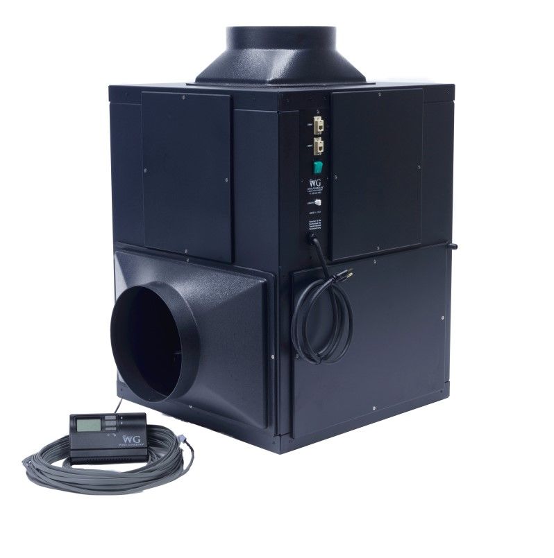
Wine Guardian Ducted and Vertical Ducted
                     Wine Cellar Cooling Systems

This document is a pictorial guide for installing the Wine Guardian Duct-
ed and Ducted Vertical system. It is not intended to replace the detailed
instructions found in the Installation, Operation and Maintenance (IOM)
manual, which includes important safety messages all installers and
owners should follow for safe and optimal performance of the system.
Complete IOM manuals can be found on the Resources and Manuals
page of wineguardian.com. If you have additional questions related to
your Wine Guardian Ducted or Vertical Ducted wine cellar cooling sys-
tem, please contact our authorized Wine Guardian distributor or your
local Wine Guardian office.

     English ............................................... page 3

     Deutsch ............................................... Seite 6

     Español ......................................... página 10

     Français ............................................. page 14

     Italiano .......................................... pagina 18

     Nederlands ..................................... pagina 22

     英語 ...................................................... 页 26

     Product overview .............................. page 30

                                           2
1.Pre-Install Start Up
A. Remove unit from box. Check for any signs of
   concealed damage, and that all optional equip-
   ment has been provided. Contact Wine Guardian
   immediately if components are missing or unit has
   been damaged in shipping.
B. Connect thermostat and cable to unit.
C. Plug unit into outlet and turn ON/OFF switch to
   “ON.” The system will turn on after a 5-minute time
   delay and the cold air section will start to deliver
   cold air. Contact Wine Guardian if the system fails
   to turn on.

 2. Installation Location

A. Wine Guardian system must be mounted hori-
   zontally on its base as shown and be level to
   +/- 1/4” (0.6 cm) end to end and 1/8” (0.3 cm)
   side to side.

B. Mount unit in a location that is easily accessible
   for service and allow at least 3 feet (1 meter) for
   clearance on either side of the system for mainte-
   nance.

C. Mount the system on the floor on an elevated plat-
   form at least 8” (20 cm) high. Unit can also be
   ceiling mounted or wall mounted by creating a
   platform to support the unit base.

3. Installing Thermostat (Wired)

A. Unit is supplied with 50 feet (15 meters) of cable
   with RJ-9 type connection along with the Re-
   mote User Interface Controller.
B. Locate the Remote User Interface within the
   room midpoint on a wall in an area with good
   airflow and away from any windows or heat
   sources.
C. Disconnect the wire from the back of the control-
   ler and route the cable to the desired mounting
   location within the room.
D. Provide a 3/4” (19 mm) diameter hole within the
   wall or racking structure to provide clearance for
   routing of the RJ-9 connection at the back of the
   controller.

                 3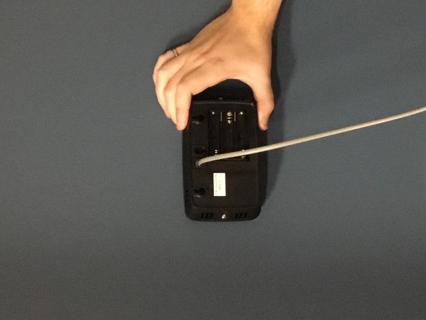
3. Installing Thermostat (Wired) — continued

               E. Remove the back plate of controller and mark
                  mounting points at the desired location.
               F. Drill two 1/8” (3 mm) holes and insert anchors within
                  mounting surface. Anchors may not be required if
                  securing to wall studs or racking. Insert screws into
                  the anchors and test fit the installation of the backing
                  plate. Tighten/loosen screws to create a snug fit.
               G. Re-attach the front cover plate to the back plate by
                  screwing it into place.
               H. Connect RJ-9 cable to the back of the remote user
                  interface and attach to the wall at the screw loca-
                  tions.
               I.        Reconnect RJ-9 cable to side of the Wine Guardian
                         unit at either COM1 or COM2.

               Note: For wireless installations or multiple remote
               interfaces, refer to the full version manual located
               at wineguardian.com/manuals

               4. Condensate Drain
               A.        Wine Guardian ducted systems are supplied with 7 feet
                         (2 meters) of ½” (13 mm) inside dimension clear tube.
               B.        Connect clear plastic tube to barbed fitting at unit and
                         route to nearest open floor drain, sink or condensate
                         pump.

NOTE: Wine Guardian unit has an internal trap. Do not double trap
piping. Failure to comply may lead to water leaks and possible wa-
ter damage to surrounding mounting area. Install drain line with a
¼ inch per linear foot (1.25 cm/linear meter) of pitch.

                    5. Installing Ductwork
                    A.    Wine Guardian unit is supplied with one (1) supply
                          duct collar and (1) return duct collar as standard
                          equipment. Install ductwork by folding back the insula-
                          tion to expose the wire reinforced vinyl duct.
                    B.    Slip the ductwork over the end of the duct collar and
                          fasten using two tie wraps supplied with the kit making
                          sure the ductwork is tight on the duct collar.

                                         4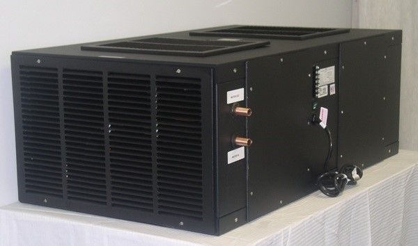
5. Installing Ductwork continued
                C. Fold the insulation back over the duct and duct collar and
                secure to collar using duct tape.

                 6. Water-Cooled Versions Only
                 A.    Connect cooling water inlet and outlet pipes to cooling
                       water source. Closed loop cooling tower, lake water, or
                       geo-thermal water source systems are recommended.

NOTE: Water-cooled WG systems have an integral water regulating
valve which may close when wine cellar temperatures are satisfied
and the unit turns off. A water bypass loop or pump control circuit
may be required for proper system operation.

                7. Turn Unit On
                A.    Turn the ON/OFF switch to the “ON” position. Switch
                      should turn green. The Remote User Interface is preset
                      to a wine cellar temperature of 55°F (13°C).
                B.    Upon start up the display will read “Hi Temp” fault.
                      Press the “Up” or “Down” button on the controller to go
                      to the main screen. The “Hi Temp” fault will remain
                      illuminated on the main screen until the temperature
                      within the wine cellar falls below 65°F (13°C).
                C.    The system will turn on after a 5-minute time delay and
                      the cold air section will start to deliver cold air. Contact
                      Wine Guardian if the system fails to turn on.

                  8. Optional Equipment
                  Humidification (Integral or Standalone) - Designed to
                  increase humidity levels in any size commercial or residential
                  wine cellar. The integrated version can only be mounted to a
                  WG system. The freestanding version can be used with WG
                  Through-the-Wall systems or any competitors’ wine cellar air
                  conditioning system.
                  Temperature/Humidity Remote Sensors - Sense and
                  control multiple locations (maximum of three) within your
                  wine cellar. Ideal for odd shaped rooms or multi-room appli-
                  cations.
                  Duct Collar Connections - Wine Guardian duct collars
                  and duct kits are specifically designed to attach directly to
                  the WG unit with no additional drilling or tapping required. Kit
                  includes duct collars, flexible duct, tie wraps and fasteners.

                                      5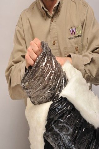
Deutsch         Wine Guardian Weinkeller Rohrkühlsystem und vertikales
                                  Rohrkühlsystem
 Dies ist eine bebilderte Installationsanleitung für das Wine Guardian Rohr- und vertikale
 Rohrkühlsystem. Die detaillierten Anweisungen der Installations-, Betriebs- und Wartung-
 sanleitung (IBW) sollten nicht ersetzt werden, da sie wichtige Sicherheitsinformationen
 beinhalten, die von Installateuren und Eigentümern für eine sichere und optimale Leis-
 tung des Geräts beachtet werden sollten.

 Lesen Sie die IBW-Anleitung für Anweisungen zur Installation von Rohrmanschetten,
 Rohrmanschetten-Sets, der Remote-Schnittstellensteuerung und Außensensoren. Voll-
 ständige IBW-Anleitungen finden Sie auf der Quellen- und HandbücherSeite der Wine
 Guardian Webseite: https://wineguardian.com/manuals.

 Wenn Sie weitere Fragen zu Ihrem Wine Guardian Weinkeller-Kühlsystem haben, kon-
 taktieren Sie bitte Ihren Wine Guardian Händler oder Ihre lokale Wine Guardian
 Geschäftsstelle.

                        1. Vor der Installation
                        A.   Nehmen Sie das Gerät aus dem Karton. Prüfen Sie das
                             Gerät auf Schäden und auf Vollständigkeit des op-
                             tionalen Zubehörs. Kontaktieren Sie Wine Guardian
                             sofort, wenn Bestandteile fehlen oder das Gerät beim
                             Transport beschädigt wurde.
                        B.   Schließen Sie das Thermostat und das Kabel an das
                             Gerät an.
                        C.   Stecken Sie es in die Steckdose und schalten Sie das
                             Gerät ein. Nach fünf Minuten schaltet sich das Gerät
                             ein und kalte Luft strömt langsam aus. Kontaktieren Sie
                             Wine Guardian, falls das Gerät nicht funktioniert.

                        2.Installationsort
                       A.    Wine Guardian-Rohrkühlsysteme müssen wie abge-
                             bildet horizontal aufgestellt werden und auf +/- 1/4
                             Zoll (0,6 cm) von einem Ende zum anderen und 1/8
                             Zoll (0,3 cm) von einer Seite zur anderen angegli-
                             chen werden.
                       B.    Montieren Sie das Gerät an einer Stelle, die einfach zu
                             erreichen ist und lassen Sie mindestens 3 Fuß (1 Me-
                             ter) Platz auf jeder Seite des Systems für Wartung-
                             sarbeiten.
                       C.    Stellen Sie das Gerät auf einer erhöhten Plattform mit
                             einem Bodenabstand von mindestens 8 Zoll (20 cm)
                             auf. Das Gerät kann auch an der Decke oder einer
                             Wand montiert werden, wenn Sie eine unterstützende
                             Plattform für das Gerät bauen—nur für Rohrsysteme.

                                             6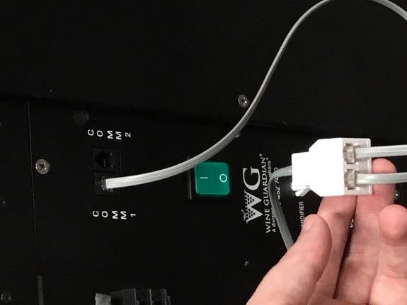
3. Thermostat verkabeln

A.   Das Gerät wird mit einem 15 Meter langen Kabel
     mit RJ-9- Anschluss für den Remote-
     Schnittstellen-Controller geliefert.
B.   Platzieren Sie die Remote-Schnittstelle im Raum
     mittig auf einer Wand in einem Bereich mit gutem
     Luftstrom und abseits von allen Fenstern oder
     Wärmequellen
C.   Trennen Sie das Kabel von der Rückseite des
     Controllers und verlegen Sie es zum gewün-
     schten Montageort im Raum.
D.   Bringen Sie ein Loch mit einem Durchmesser von
     19 mm in der Wand oder in der Regalstruktur an,
     um Platz für den RJ-9-Anschluss an der
     Rückseite des Controllers zu ermöglichen.
E.   Entfernen Sie die Rückplatte des Controllers und
     markieren Sie die Montagepunkte am gewün-
     schten Montageort.
F.   Bohren Sie zwei 3 mm (1/8“) große Löcher und
     führen Sie die Dübel in die Montageoberfläche
     ein. Dübel sind nicht erforderlich, wenn sie an
     einem Wand- oder Regalsystem befestigt
     werden. Setzen Sie die Schrauben in die Dübel
     ein und testen Sie die Installation der Rückplatte.
     Ziehen Sie die Schrauben an / lösen Sie sie, um
     einen festen Halt zu erzielen.
G. Bringen Sie die vordere Abdeckplatte wieder an,
   indem Sie sie an der hinteren Platte festschrau-
   ben.
H.   Verbinden Sie das RJ-9-Kabel an der Rückseite
     der Remote-Schnittstelle an und befestigen Sie
     es an den Schraubstellen an der Wand.
I.   Verbinden Sie erneut das RJ-9-Kabel mit der
     Seite der Wine Guardian-Einheit entweder mit
     COM1 oder COM2 .

Hinweis: Informationen zu drahtlosen Installationen
oder mehreren Remote-Schnittstellen finden Sie im
Vollversionshandbuch unter wineguardian.com/
manuals

                7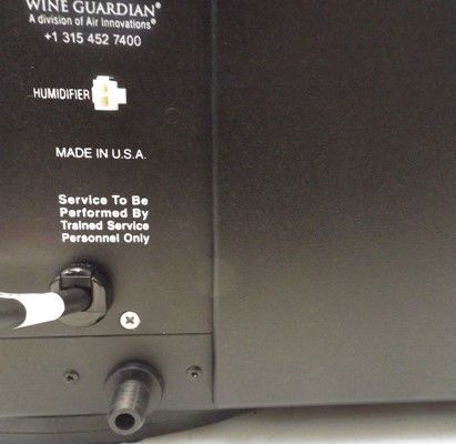
4.Kondensatableiter
                 A.    Wine Guardian-Rohrkühlsysteme und vertikale
                       Rohrkühlsysteme sind mit einem durchsichtigen Rohr
                       mit einem Innenmaß von 7 Fuß (2 m) x 0,5 Zoll (13 mm)
                       ausgestattet.
                 B.    Schließen Sie das durchsichtige Plastikrohr an die
                       Stecknippelverbindung des Geräts an und leiten Sie es
                       zum nächstgelegenen offenen Bodenablauf,
                       Waschbecken oder zur nächsten Kondensatpumpe.

HINWEIS: Das Wine Guardian-Gerät hat einen inneren Ableiter. Verd-
oppeln Sie nicht die Leitungen. Dies kann zu Leckstellen und Wasser-
schäden in der Montageumgebung führen. Installieren Sie die Ablasslei-
tung mit ¼ Zoll Abstand pro laufendem Meter (1,25 cm/lfm).

                  5.Installation der Luftführungsanlage
                  A.    Wine Guardian-Systeme sind standardmäßig mit (1)
                        Zuluftleitung und (1) Rückluftleitung ausgestattet.

                  B.    Installieren Sie die Luftführungsanlage, indem Sie die
                        Isolierung zurückschlagen und somit das
                        drahtverstärkte Vinylrohr freilegen. Setzen Sie die
                        Luftführungsanlage auf die Rohrmanschette auf und
                        befestigen Sie sie mit den zwei mitgelieferten
                        Kabelbindern und stellen Sie sicher, dass die Luftfüh-
                        rungsanlage fest an die Rohrmanschette anges-
                        chlossen ist.

                  C.    Schlagen Sie die Isolierung zurück über das Rohr und
                        befestigen Sie sie mit Klebeband an der Manschette.

                        6.Nur für wassergekühlte Versionen
                        A.     Verbinden Sie die Kühlwassereingangs- und Aus-
                             gangsrohre mit der Kühlwasserquelle. Es werden
                             Quellsysteme wie der geschlossene Kühlkreisturm,
                             Seewasser oder geothermisches Wasser empfohlen.

HINWEIS: Wine Guardian Wassergekühlte Systeme besitzen ein
eingebautes Wasserregelventil, das sich schließt, wenn die gewünschte
Weinkellertemperatur erreicht ist, und das Gerät schaltet sich aus. Eine
Wasserumleitung oder eine Pumpensteuerschaltung werden möglicher-
weise für einen ordnungsgemäßen Betrieb benötigt.

                                        8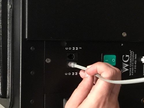
7.Einschalten des Geräts
A.   Stellen Sie den An-/Aus-Schalter auf „AN“. Der Schal-
     ter leuchtet nun grün. Die Remote-Bedienoberfläche ist
     auf eine Weinkeller-Temperatur von 55 °F (13 °C)
     voreingestellt.
B.   Am Anfang zeigt das Display den Fehler „Hohe Temp”
     an. Drücken Sie die „Auf“- oder „Ab“-Taste auf der
     Steuerung, um zum Hauptbildschirm zu gelangen. Die
     Fehlermeldung leuchtet auf dem Hauptbildschirm auf,
     bis die Temperatur im Weinkeller unter 65 °F (13 °C)
     fällt.
C.   Nach fünf Minuten schaltet sich das Gerät ein und
     kalte Luft strömt langsam aus. Kontaktieren Sie Wine
     Guardian, falls das Gerät nicht funktioniert.

8.Optionale Ausstattung
Befeuchtung (Integriert oder Freistehend) Erhöht
Feuchtigkeit in Weinkellern jeglicher Größe, ob privat oder
geschäftlich. Die integrierte Version kann nur mit einem
Wine Guardian-System genutzt werden. Die freistehende
Version kann mit Durch-die-Wand-Systemenvon Wine
Guardian oder jeglichen anderen Weinkeller-Kühlsystemen
kombiniert werden.

Temperatur-/Feuchtigkeits-Außensensoren
Kontrollieren mehrere Stellen (maximal drei) in Ihrem Wein-
keller. Ideal für ungewöhnlich geschnittene Räume und
Anwendungen für mehrere Räume.

Rohrmanschetten-Anschlüsse
Die Wine Guardian Rohrmanschetten und Rohr-Sets kön-
nen ohne zusätzliches Bohren an die WG Einheit anges-
chlossen werden. Ausstattung enthält Rohrmanschetten,
ein flexibles Rohr, Kabelbinder und Halter.

                   9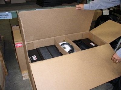
Español            Sistemas de Refrigeración Wine Guardian con
                  Conductos y conductos verticales Wine Guardian.
A continuación encontrará una guía ilustrada para la instalación del sistema de
conductos y conductos verticales Wine Guardian. No se pretende sustituir las
instrucciones detalladas que se encuentran en el manual de instalación,
operación y mantenimiento (IOM), el cual incluye mensajes de seguridad im-
portantes que todos los instaladores y propietarios deben seguir para un rendi-
miento seguro y óptimo del sistema.
Consulte en el manual de instalación, operación y mantenimiento (IOM) las
instrucciones de instalación relacionadas con los cuellos de los conductos,
conjuntos de cuellos de los conductos, controles de la interfaz remota o sen-
sores remotos. Los manuales IOM completos se pueden encontrar en la pági-
na Recursos y Manuales de la página web de Wine Guardian: https://
wineguardian.com/manuals.

Si tiene más preguntas relacionadas con el sistema de refrigeración de Wine
Guardian, por favor, póngase en contacto con su distribuidor autorizado o con
la oficina local de Wine Guardian.

                     1. Pre-Instalación para puesta en marcha
                     A.     Retire la unidad de la caja. Compruebe si hay algún da-
                            ño oculto y que todo el equipo opcional está dentro de la
                            caja. Contacte con Wine Guardian de inmediato en caso
                            de que falten componentes o de que la unidad haya sido
                            dañada durante el envío.
                     B.     Conecte el termostato y enchúfelo a la unidad.
                     C. Enchufe la unidad a la salida y coloque el interruptor ON/
                        OFF en "ON". El sistema se encenderá después de 5
                        minutos y la sección de aire frío empezará a propor-
                        cionar aire frío. Póngase en contacto con Wine Guardian
                        en caso de que el sistema no se encienda.

                    2. Ubicación de la instalación
                    A.      El sistema de vino de Wine Guardian debe ser mon-
                            tado horizontalmente en su base como se muestra y
                            estar nivelado a +/- 1/4" (0,6 cm) de extremo a fin y
                            1/8" (0,3 cm) de lado a lado.
                    B.      Monte la unidad en un lugar que sea fácilmente accesi-
                            ble para el servicio y deje por lo menos 3 pies (1 metro)
                            de espacio libre a los dos lados del sistema para su
                            mantenimiento.
                    C.      Monte el sistema en el suelo sobre una plataforma ele-
                            vada al menos 8" (20 cm) de altura. La unidad también
                            puede montarse en el techo o en la pared mediante la
                            creación de una plataforma para apoyar la base de la
                            unidad (en el sistema con conductos únicamente).

                                         10
3. Instalación del termostato (cableado)
A. La unidad viene con 50 pies (15 metros) de cable con
conexión de tipo RJ-9 junto con el controlador de
interfaz remota para usuario.
B. Posicione la interfaz remota para usuario en el medio
de una pared que se encuentre en un área con buen
flujo de aire y apartada de ventanas o fuentes de
calor.
C. Desconecte el cable de la parte posterior del
controlador y dirija el cable a la ubicación deseada
para el montaje dentro de la habitación.
D. Haga un orificio de 3/4” (19 mm) de diámetro en la
pared o estanterías para garantizar un espacio libre
para el enrutamiento de la conexión RJ-9 en la parte
posterior del controlador.
E. Retire la placa posterior del controlador y marque los
puntos de montaje en la ubicación deseada.
F. Taladre dos orificios de 1/8” (3 mm) e inserte los
anclajes dentro de la superficie de montaje. Es
posible que no se requieran anclajes si se aseguran a
montantes de pared o estanterías. Introduzca tornillos
en los anclajes y pruebe el ajuste del montaje de la
placa de apoyo. Apriete/afloje los tornillos hasta
alcanzar un ajuste óptimo.
G. Vuelva a colocar la cubierta frontal en la placa
posterior atornillándola en su lugar.
H. Conecte el cable RJ-9 a la parte posterior de la
interfaz remota para usuario y acóplela a la pared en
las posiciones de los tornillos.
I. Vuelva a conectar el cable RJ-9 en el lateral de la
unidad Wine Guardian ya sea a COM1 o COM2.
Nota: Para instalaciones inalámbricas o
múltiples interfaces remotas, consulte la versión
completa del manual que se encuentra en
wineguardian.com/manuals
114. Drenaje condensado
A. Los sistemas de conductos y conductos verticales Wine
Guardian se suministran con 7 pies (2 metros) de tubo
transparente con una apertura interior de ½" (13 mm).
B. Conecte el tubo transparente a la boquilla de la unidad
y diríjalo hacia el sumidero en el suelo más cercano,
fregadero o bomba de condensado.
NOTA: La unidad Wine Guardian tiene un sifón interno. No du-
plique las tuberías. Dicho incumplimiento puede dar lugar a fugas
de agua y posibles daños en el entorno del área de montaje. In-
stale la línea de drenaje con un ¼ de pulgada por pie lineal (1,25
cm/metro lineal) del terreno.
5. Instalación de los conductos
A. Los sistemas de conductos y conductos verticales Wine
Guardian se suministran con un (1) cuello para el con-
ducto de suministro y (1) cuello para el conducto de
retorno como equipo estándar.
B. Instale el conducto plegando el aislamiento para ex-
poner el conducto de vinilo reforzado con alambre. De-
slice el conducto sobre el extremo del cuello del conduc-
to y sujete usando las dos abrazaderas suministradas
con el conjunto, asegurándose de que el conducto está
apretado sobre el cuello.
C. Pliegue de nuevo el aislamiento sobre el conducto y el
cuello del conducto y asegúrelo al cuello con cinta adhe-
siva.
6. Sólo para las versiones refrigeradas por agua
A. Conecte las tuberías de entrada y salida para la
refrigeración por agua a la fuente de agua. Se
recomiendan torres de refrigeración de circuito
cerrado, agua de lago o sistemas de fuente de
agua geotérmica.
NOTA: Los sistemas Wine Guardian refrigerados por agua tienen una vál-
vula integral de regulación del agua que se puede cerrar cuando las tem-
peraturas de la bodega sean satisfactorias y entonces la unidad se apaga-
rá. Un circuito de derivación de agua o el circuito de control de bomba
pueden ser necesarios para el funcionamiento adecuado del sistema.
127. Encendido de la unidad
A. Coloque el interruptor ON/OFF en la posición "ON". El
interruptor deberá ponerse de color verde. La interfaz
de usuario remoto está programada para una tempera-
tura de bodega de 55 °F (13 °C).
B. Tras la puesta en marcha, la pantalla mostrará el men-
saje "Hi Temp" por defecto. Presione el botón "Up" o
"Down" en el controlador para ir a la pantalla principal.
El "Hi Temp" por defecto permanecerá iluminado en la
pantalla principal hasta que la temperatura dentro de la
bodega caiga por debajo de 65 °F (13 °C).
C. El sistema se encenderá después de 5 minutos y la
sección de aire frío empezará a proporcionar aire frío.
Póngase en contacto con Wine Guardian si el sistema
no se enciende.
8. Equipamiento opcional
Humidificación (integral o independiente) Diseñado
para aumentar los niveles de humedad en bodegas
comerciales o residenciales de cualquier tamaño. La
versión integrada sólo puede ser montada sobre un siste-
ma Wine Guardian. La versión independiente puede ser
utilizada con los sistemas de Wine Guardian o con
cualquier sistema de aire acondicionado para bodegas de
sus competidores.
Sensores remotos de temperatura/humedad
Vigile y controle múltiples ubicaciones (máximo de tres)
dentro de su bodega. Ideal para salas con formas irregula-
res o aplicaciones multisala.
Conexiones a los cuellos de los conductos
Los cuellos y conjuntos de cuellos de los conductos de
Wine Guardian están diseñados específicamente para
conectarse directamente a la unidad WG sin una perfo-
ración adicional requerida. El conjunto incluye cuellos de
los conductos, conductos flexibles, abrazaderas y fija-
dores.
13Système de refroidissement de cave à vin canalisé et à con-
Français duits verticaux Wine Guardian
Le présent document est un guide illustré pour l'installation de climatiseurs
verticaux canalisés et canalisés Wine Guardian. Il n'a pas pour objet de rem-
placer les instructions détaillées dans le manuel d’installation, de fonctionne-
ment et d’entretien qui comprend d'importantes consignes de sécurité que tout
installateur ou propriétaire se doit de respecter afin d'assurer un fonctionne-
ment optimal et sécurisé de l'appareil.
Reportez-vous au manuel d’installation, de fonctionnement et d’entretien pour
plus d'informations concernant les colliers pour conduits, les kits de colliers
pour conduits, les commandes à distance de l'interface ou les capteurs à dis-
tance. Vous pouvez trouver des manuels d'installation, de fonctionnement et
d'entretien complets sur la page "Resources & Manuals" (ressources et ma-
nuels) de notre site internet Wine Guardian: https://wineguardian.com/manuals.
Pour toute question concernant les climatiseurs de caves à vin Wine Guardian,
veuillez contacter votre revendeur agréé Wine Guardian ou la succursale Wine
Guardian la plus proche.
1. Commencement de la pré-installation
A. Retirez l'appareil de son emballage. Vérifiez qu'il n'est
pas endommagé et que tout le matériel en option est
fourni. Contactez immédiatement l'entreprise Wine
Guardian s'il manque des éléments ou si le climatiseur a
été endommagé lors du transport.
B. Branchez le thermostat et le câble au climatiseur.
C. Branchez le climatiseur à une prise électrique et activez
l'interrupteur ON/OFF en position "ON". Le climatiseur
s'activera après 5 minutes et le compartiment de re-
froidissement commencera à produire de l'air froid. Con-
tactez l'entreprise Wine Guardian si le climatiseur ne
s'allume pas.
2. Emplacement d'installation
A. Le climatiseur canalisé Wine Guardian doit être in-
stallé horizontalement sur son socle (comme montré
sur l'image) et être à niveau avec une différence de +/
- 0,6 cm dans le sens de la longueur et de 0,3 cm
dans le sens de la largeur.
B. Installez l'appareil dans un endroit facilement accessible
pour toute réparation et laissez au moins 1 mètre de
chaque côté du système de refroidissement pour faciliter
l'entretien du climatiseur.
C. Montez le climatiseur sur le sol sur une plate-forme d'une
hauteur minimale de 20 cm. Le climatiseur peut égale-
ment être installé au plafond ou encastré dans un mur à
l'aide d'une plate-forme capable de soutenir la base du
climatiseur (climatiseur canalisé uniquement).
143. Connexion du thermostat
A. L’unité est fournie avec un câble de 15 mètres
(50 pieds) muni d’un raccordement de type RJ-9 avec
une commande d’interface à distance.
B. Placer l’interface utilisateur à distance dans la pièce, au
milieu d'un mur, dans une zone dotée d'une bonne
aération et à l’écart de toute fenêtre ou source de cha-
leur.
C. Déconnecter le câble de l’arrière de la commande et
acheminer le câble jusqu’à l’endroit de la pièce prévu
pour l’installation.
D. Prévoir un trou de 19 mm (0,75 pouce) de diamètre
dans le mur ou la structure rack pour laisser un espace
suffisant pour le raccordement RJ-9 à l’arrière de la
commande.
E. Retirer la plaque arrière du dispositif de contrôle et
marquer les points de montage à l’endroit souhaité.
F. Percer deux trous de 3 mm (1/8 pouce) et insérer des
boulons de fixation dans la surface de montage. Il est
possible que les boulons de fixation ne soient pas né-
cessaires en cas de fixation à des poteaux muraux ou
à des rayons. Insérer des vis dans les boulons de fixa-
tion et vérifier que l’installation s’adapte à la plaque
arrière. Serrer/Desserrer les vis pour un bon ajuste-
ment.
G. Remettre en place la plaque de protection avant en la
vissant sur la plaque arrière.
H. Connecter le câble RJ-9 à l’arrière de l’interface utilisa-
teur à distance et l’attacher au mur à l’endroit prévu
pour le vissage.
I. Reconnecter le câble RJ-9 au côté de l’unité Wine
Guardian unit en utilisant la connexion COM1 ou
COM2.
Remarque: pour les installations sans fil ou
plusieurs interfaces à distance, reportez-vous au
manuel de la version complète disponible sur
wineguardian.com/manuals
154. Évacuation de la condensation
A. Les climatiseurs (verticaux) à conduits Wine Guardian
sont fournis avec 2 mètres de de tuyau transparent de 13
mm de diamètre.
B. Branchez le tuyau en plastique transparent au raccord
cannelé de l'appareil et connectez-le à une pompe à con-
densats, à un évier ou à un tuyau d'évacuation de la
pièce à plafond à solives apparentes la plus proche.
REMARQUE : l'appareil Wine Guardian possède un siphon intérieur. N'in-
stallez pas de double siphon. Le non-respect de cette consigne peut
provoquer des fuites d'eau et d'éventuels dégâts des eaux à proximité de
l'emplacement d'installation. Installez le tuyau d'évacuation avec une in-
clinaison de 1,25 cm par mètre.
5. Installation du système de gaines
A. Les climatiseurs Wine Guardian sont fournis avec un
(1) collier pour conduits d'entrée et un (1) collier pour
conduits de sortie comme matériel réglementaire.
B. Installez le système de gaines en repliant l'isolant pour
laisser apparaître le câble pour conduits en vinyle
renforcé. Glissez le système de gaines au-dessus de
l'embout du collier pour conduits et serrez-le à l'aide
de deux attaches autobloquantes fournies dans le kit
en vous assurant que le système de gaines est serré
sur le collier pour conduits.
C. Repliez l'isolant sur le conduit et le collier pour con-
duits et fixez-le au collier à l'aide de ruban adhésif.
6. Systèmes de refroidissement uniquement
A. Branchez les tuyaux d'entrée et de sortie de re-
froidissement à la source du climatiseur. Les ap-
pareils à source d'eau géothermale, d'eau de lac ou
d'eau de tours de refroidissement fermées sont
recommandés.
REMARQUE : les systèmes de refroidissement Wine Guardian possèdent
une valve de régulation d'eau intégrée pouvant se fermer lorsque les
températures de la cave à vin sont satisfaisantes et lorsque l'appareil est
éteint. Un circuit de contrôle d'eau dérivé par pompe ou en boucle peut
être nécessaire pour assurer un fonctionnement optimal de l'appareil.
167. Mise en marche de l'appareil
A. Mettez l'interrupteur ON/OFF en position "ON". La lu-
mière doit être verte. La commande à distance de l'inter-
face utilisateur est préconfigurée pour une température
de cave à vin de 13°C.
B. Lors de la mise en marche de l'appareil, l'écran affichera
un message d'erreur "Hi Temp" (haute température) .
Appuyez sur les flèches "haut" et "bas" de la commande
à distance pour accéder à l'écran principal. Le message
d'erreur "Hi temp" restera activé sur l'écran principal
jusqu'à ce que la température de la cave à vin devienne
inférieure à 13°C.
C. L'appareil s'allumera après 5 minutes et le compartiment
d'air froid commencera à produire de l'air froid. Con-
tactez l'entreprise Wine Guardian si l'appareil ne s'allume
pas.
8. Matériel en option
Humidification (intégrale ou autonome). Conçue pour
augmenter les taux d'humidité de toute cave à vin privée
ou d'entreprise de toute taille. La version intégrée ne
peut être montée qu'à un appareil Wine Guardian. La
version autostable peut être utilisée avec les climatiseurs
traversants Wine Guardian ou avec tout appareil concur-
rent à air conditionné pour cave à vins.
Capteurs à distance d'humidité/de température
Captent et contrôlent plusieurs endroits (trois au maxi-
mum) à l'intérieur de la cave à vin. Conviennent par-
faitement pour une utilisation dans plusieurs pièces ou
dans des pièces de forme irrégulière.
Branchements de colliers pour conduits
Les kits de conduits et les colliers pour conduits Wine
Guardian sont particulièrement conçus pour fixer di-
rectement l'appareil WG et ne nécessitent aucun autre
perçage ni saignée. Le kit inclut des colliers pour con-
duits, un conduit flexible, des attaches autobloquantes et
de fixations.
17Italiano
Sistema di raffreddamento cantine canalizzato e verticalmente cana-
lizzato Wine Guardian
Ciò che segue è una guida illustrata per l'installazione del sistema cana-
lizzato e verticalmente canalizzato Wine Guardian. Il presente documento
non sostituisce le dettagliate istruzioni in allegato al manuale di installazione,
funzionamento e manutenzione (IFM), che include importanti informazioni di
sicurezza a cui tutti gli installatori e i proprietari dovrebbero far riferimento
per garantire una prestazione sicura e ottimale del sistema.
Consultare il manuale IFM per le istruzioni sull’installazione relative ai collari
per il condotto, ai kit di collari per il condotto, ai comandi di interfaccia a dis-
tanza o ai sensori a distanza. I manuali IFM completi si possono trovare
attraverso la pagina web Resources & Manuals del sito Wine Guardian:
https://wineguardian.com/manuals.
Qualora ci siano ulteriori dubbi relativi al suo sistema di raffreddamento
Wine Guardian, la preghiamo di contattare il suo distributore Wine Guardian
autorizzato o il più vicino ufficio Wine Guardian.
1. Messa in funzione pre-installazione
A. Rimuovere l'unità dalla scatola. Controllare che non ci
sia alcun segno di danno nascosto e che tutta l'attrez-
zatura opzionale sia stata fornita. Contattare immedi-
atamente Wine Guardian, se vi sono componenti
mancanti o se l'unità è stata danneggiata durante il
trasporto.
B. Collegare il termostato e il cavo all'unità.
C. Collegare l'unità alla presa e posizionare l'interruttore
d'accensione ON/OFF su "ON". Il sistema si accend-
erà dopo 5 minuti di attesa e la sezione ad aria fredda
inizierà a rilasciare aria fredda. Contattare Wine
Guardian se il sistema non si accende.
2.Posizione dell'installazione
A. Il sistema canalizzato Wine Guardian dev'essere
montato in orizzontale sulla sua base, come
mostrato, e deve presentare una planarità di circa
0,6 cm da un'estremità all'altra e 0,3 cm da una
parte all'altra.
B. Montare l'unità in una posizione che sia facilmente
accessibile per i futuri controlli e che lasci almeno un
metro di spazio su entrambi i lati del sistema per la
manutenzione.
C. Montare il sistema sul pavimento al di sopra di una
pedana alta almeno 20 cm. L'unità può anche essere
montata sul soffitto o sulla parete creando una piatta-
forma di sostegno per la base dell'unità (solo per siste-
ma canalizzato).
183. Installazione del termostato (cablato)
A. L’unità è dotata di un cavo da 15 m (50 piedi) con tipo
di connessione RJ-9 oltre al comando di interfaccia
utente remoto.
B. Posizionare l’interfaccia utente remoto al centro della
stanza, su una parete in una zona con un buon flusso
d’aria e lontano da finestre o fonti di calore.
C. Scollegare il filo dal retro del comando e portare il
cavo verso il punto di montaggio desiderato all’interno
della stanza.
D. Praticare un foro dal diametro di 19 mm (3/4”) nella
parete o nella scaffalatura, per garantire abbastanza
spazio per il collegamento della connessione RJ-9 al
retro del comando.
E. Rimuovere la piastra posteriore del dispositivo e
segnare i punti di montaggio nella posizione
desiderata.
F. Praticare due fori da 3 mm (1/8”) e inserire i supporti
nella superficie di montaggio. I punti di supporto non
sono necessari se si fissa il dispositivo a travi o
scaffali. Inserire viti nei punti di supporto e
posizionare la piastra posteriore. Stringere/allentare le
viti per un perfetto posizionamento.
G. Ricollegare la piastra anteriore alla piastra posteriore
attraverso le viti.
H. Collegare il cavo RJ-9 al retro dell’interfaccia utente
remoto e fissarlo alla parete in prossimità della
posizione delle viti.
I. Ricollegare il cavo RJ-9 al lato dell’unità Wine
Guardian tramite COM1 o COM2.
Nota: per installazioni wireless o interfacce
remote multiple, fare riferimento al manuale della
versione completa disponibile su
wineguardian.com/manuals
194. Tubo di drenaggio condensa
A. I sistemi Wine Guardian canalizzati e verticalmente can-
alizzati sono dotati di un tubo trasparente lungo 2 m per
13 mm di diametro interno.
B. Collegare il tubo di plastica trasparente al raccordo rin-
forzato sull'unità e portarlo al più vicino tombino aperto,
rubinetto o pompa di condensa.
NOTA: l'unità Wine Guardian presenta un sifone interno. Non bloccare la
tubatura. La mancata osservanza di questo accorgimento potrebbe
provocare una perdita d'acqua e un possibile danno causato dall'acqua
alla zona di montaggio circostante. Installare la linea di drenaggio con
1,25 cm per metro lineare di campo.
5. Installazione della conduttura
A. I sistemi Wine Guardian sono dotati di un (1) collare
per il condotto di fornitura e un (1) collare per il con-
dotto di ritorno come dotazione standard.
B. Installare la conduttura ripiegando all'indietro il mate-
riale isolante per esporre il condotto in vinile rinforza-
to con filo metallico. Far scivolare la conduttura sopra
l'estremità del collare e fissarla usando le due fascette
fornite nel kit, assicurandosi che la conduttura sia
aderente al collare del condotto.
C. Ripiegare il materiale isolante all'indietro sopra il con-
dotto ed il collare del condotto, quindi fissarlo al col-
lare usando del nastro adesivo isolante.
6. Solo per versioni con raffreddamento ad acqua
A. Collegare i tubi di entrata e di uscita dell'acqua di
raffreddamento alla fonte dell'acqua di raffreddamen-
to. Sono raccomandati sistemi che utilizzano una torre
di raffreddamento a circuito chiuso, acqua lacustre o
acqua geotermica come fonte.
NOTA: i sistemi di raffreddamento ad acqua Wine Guardian presentano
una valvola integrata per la regolazione dell'acqua che può essere chiusa
al raggiungimento della temperatura ottimale nella cantina e al conse-
guente spegnimento dell'unità. Un circuito di controllo della pompa o di
bypass dell'acqua potrebbe essere necessario per un appropriato
funzionamento del sistema.
207. Accensione dell'unità
A. Posizionare l'interruttore di accensione ON/OFF su "ON".
L'interruttore dovrebbe diventare verde. L'Interfaccia
utente a distanza è preimpostata su una temperatura di
13°C all'interno della cantina.
B. Subito dopo l'avvio viene visualizzato il messaggio di
errore "Hi Temp" sul display. Premere il pulsante "Su" o
"Giù" sul comando per accedere alla schermata princi-
pale. Il messaggio di errore "Hi Temp" rimarrà illuminato
sulla schermata principale finché la temperatura all'inter-
no della cantina non sarà scesa al di sotto dei 13°C.
C. Il sistema si accenderà dopo 5 minuti di attesa e la
sezione ad aria fredda inizierà a rilasciare aria fredda.
Contattare Wine Guardian se il sistema non si accende.
8. Apparecchiatura opzionale
Umidificatore (integrale o a sé stante) Ideato per au-
mentare i livelli di umidità nelle cantine per vini commer-
ciali o residenziali di ogni dimensione. La versione integra-
ta può essere montata solo su un sistema Wine Guardian.
La versione indipendente può essere utilizzata con i sis-
temi ad incasso Wine Guardian o con qualsiasi altro siste-
ma di aria condizionata per cantine dei nostri concorrenti.
Sensori di temperatura/umidità a distanza
Consentono di rilevare misure e controllare più posizioni
(massimo tre) all'interno della cantina. Ideali per stanze
con perimetro particolare o applicazioni che interessano
più stanze.
Allacciamenti dei collari per il condotto
I collari per il condotto e i kit per condotti Wine Guardian
sono appositamente ideati per essere collegati diretta-
mente all'unità WG senza l'uso di ulteriore trapanatura o
spillatura. Il kit include collari per il condotto, condotto
flessibile, fascette e viti.
21Nederlands Wine Guardian met kanalen en verticaal met kanalen
Wijnkelder koelsystemen
Dit document is een illustratieve handleiding voor het installeren van het Wine
Guardian systeem met kanalen en verticaal systeem met kanalen. Het is niet
de bedoeling om de gedetailleerde instructies te vervangen die u vindt in de
installatie-, bedienings- en onderhoudshandleiding (IOM), welke ook bel-
angrijke veiligheidsinformatie bevat die alle installateurs en eigenaren moeten
opvolgen voor veilige en optimale prestaties van het systeem.
Raadpleeg de IOM handleiding voor installatie-instructies met betrekking tot
kanaalmoffen, mof kits, afstandsbedieningen of externe sensoren. De volledige
IOM handleidingen kunnen gevonden worden via de Resources & Manuals
pagina van de Wine Guardian website: https://wineguardian.com/manuals.
Als u nog vragen hebt over uw Wine Guardian wijnkelder koelsysteem, neem
dan contact op met uw erkende Wine Guardian distributeur of uw lokale Wine
Guardian kantoor.
1. Pre-installatie starten
A. Neem het apparaat uit de doos. Controleer op
tekenen van verborgen schade en of alle optionele
apparatuur geleverd is. Neem onmiddellijk contact op
met Wine Guardian als er onderdelen ontbreken of
als het apparaat tijdens het transport beschadigd is.
B. Sluit de thermostaat en de kabel aan op het appa-
raat.
C. Steek de stekker in het stopcontact en zet de AAN/
UIT-schakelaar op “AAN”. Het systeem schakelt na
een vertraging van 5 minuten in en het koude lucht
gedeelte begint met het geven van koude lucht.
Neem contact op met Wine Guardian als het systeem
niet inschakelt.
2. Plaats van de installatie
A. Het Wine Guardian systeem met kanalen dient als
getoond horizontaal op zijn basis gemonteerd te
worden en waterpas te staan binnen 0,6 cm over
de lange zijde en binnen 0,3 cm over de korte
zijde.
B. Monteer het apparaat op een makkelijk toegankelijke
locatie zodat u er goed bij kunt voor service en laat
tenminste 1 meter aan beide zijden vrij voor onder-
houd.
C. Monteer het systeem op de vloer op een verhoogd
platform van ten minste 20 cm hoog. Het apparaat
kan ook aan de muur of aan het plafond gemonteerd
worden door een platform te maken dat het apparaat
ondersteunt - alleen bij toepassing met kanalen.
223. Bedraden thermostaat
A. Unit wordt geleverd met 50 voet (15 meter) kabel met
RJ-9 type verbinding samen met de Remote User
Interface Controller.
B. Zoek de externe gebruikersinterface in het middelpunt
van de kamer op een muur in een gebied met een
goede luchtstroom en weg van ramen of warmteb-
ronnen.
C. Koppel de draad los van de achterkant van de con-
troller en leid de kabel naar de gewenste montagelo-
catie in de ruimte.
D. Zorg voor een gat met een diameter van 19 mm in de
wand of de rackstructuur om ruimte te bieden voor de
routering van de RJ-9-verbinding aan de achterkant
van de controller.
E. Verwijder de achterplaat van de controller en markeer
bevestigingspunten op de gewenste locatie.
F. Boor twee 3 mm gaten en steek ankers in het monta-
geoppervlak. Ankers zijn mogelijk niet nodig als ze
vastzetten aan wandnoppen of rekken. Steek
schroeven in de ankers en test passen de installatie
van de achterplaat. Draai/los schroeven om een
knusse pasvorm te creëren.
G. Bevestig de voorste afdekplaat op de achterplaat
door deze op zijn plaats te schroeven.
H. Sluit de RJ-9-kabel aan de achterkant van de externe
gebruikersinterface en bevestig op de schroeflocaties
aan de muur.
I. Sluit de RJ-9 kabel opnieuw aan op de zijkant van de
Wine Guardian-eenheid op COM1 of COM2.
Opmerking: Raadpleeg voor draadloze installat-
ies of meerdere externe interfaces de volledige
versiehandleiding op wineguardian.com/manuals
234. Condensafvoer
A. Wine Guardian systemen met kanalen en verticaal met
kanalen worden geleverd met 2 meter heldere buis met
13 mm binnendiameter.
B. Sluit de heldere kunststof buis aan op de geribbelde
aansluiting op het apparaat en leid deze naar de
dichtstbijzijnde vloerput, gootsteen of condensaatpomp.
LET OP: De Wine Guardian heeft een ingebouwde sifon. Monteer niet nog
een sifon in de afvoer. Wanneer dit niet wordt opgevolgd kan waterlek-
kage en waterschade aan de montageomgeving het gevolg zijn. Monteer
de afvoer met een afloop van 1,25 cm per meter.
5 Installeren van de kanalen.
A. De Wine Guardian systemen worden standaard gelev-
erd met één (1) voedingkanaalmof en (1) retourka-
naalmof.
B. Installeer de kanalen door de isolatie terug te vouwen
en zo het met draad versterkte vinyl kanaal bloot te
leggen. Schuif het kanaal over het einde van de ka-
naalmof en zet deze vast met twee meegeleverde tie-
raps en zorg dat het kanaal goed vast zit.
C. Vouw de isolatie terug over het kanaal en de ka-
naalmof en zet de isolatie vast met duct tape.
6. Alleen de watergekoelde versies
A. Sluit de koelwater ingangs- en uitgangsbuizen
aan op de koelwaterbron. Een koeltoren met
gesloten systeem, water van een meer of geo-
thermale waterbron systemen worden aanbevo-
len.
LET OP: Wine Guardian Watergekoelde systemen hebben een geïnte-
greerde waterregelklep die kan sluiten wanneer de temperatuur in de
wijnkelder is bereikt en het apparaat af slaat. Een wateromloopkanaal of
pompregelcircuit kan benodigd zijn voor correcte werking van het sys-
teem.
247. Zet het apparaat aan
A. Zet de AAN/UIT-schakelaar in de “AAN” stand. De
schakelaar dient groen te worden. De afstandsbe-
dieningseenheid is ingesteld op een wijnkelder tem-
peratuur van 13 °C.
B. Na starten zal het scherm “Hi Temp” fout aangeven.
Druk op de “Omhoog” of “Omlaag” knop op de een-
heid om naar het hoofdscherm te gaan. De “Hi Temp”
fout blijft op het scherm staan totdat de temperatuur
onder de 13°C komt.
C. Het systeem schakelt na 5-minuten vertraging in en
het koude lucht gedeelte zal koude lucht gaan lev-
eren. Neem contact op met Wine Guardian als het
systeem niet inschakelt.
8. Optionele apparatuur
Luchtbevochtiging (integraal of afzonderlijk)
Ontworpen om de vochtigheid in elke commerciële of
privé wijnkelder te verhogen. De geïntegreerde versie
kan alleen gemonteerd worden op een Wine Guardian
systeem. De vrijstaande versie kan gebruikt worden met
het Wine Guardian Door-de-muur systeem of een aircon-
ditioning systeem van een concurrent.
Temperatuur/Vochtigheidssensoren
Controleer en regel meerdere plaatsen (maximaal drie)
binnen uw wijnkelder. Ideaal voor vreemd gevormde
ruimtes of toepassingen met meerdere ruimtes.
Kanaalmoffen aansluitingen
De Wine Guardian kanaalmoffen en kanaal-kits zijn spec-
ifiek ontworpen om direct te monteren aan de WG een-
heid zonder dat boren of tappen nodig is. Een kit bevat
moffen, een flexibel kanaal, tie-raps en bevestigingsma-
teriaal.
25英語
葡萄酒守护者(Wine Guardian)管道和垂直管道
酒窖冷却系统
下面是安装葡萄酒守护者管道和垂直管道系统的指南。本指南不能替代安装、操
作和维护(IOM)手册中的说明,该手册包括所有安装者和所有者为实现该系统安
全和最优性能应遵循的重要安全信息。
请参考IOM手册,了解与管道接口套管、管道套管套件、远程界面控制或遥感器
有关的说明。可在葡萄酒守护者网站的资源和手册找到完整IOM手册: https://
wineguardian.com/manuals.
如有关于葡萄酒守护者酒窖冷却系统的其他问题,请联系葡萄酒守护者授权经销
商或本地的葡萄酒守护者办事处。
1.安装前启动
A. 将装置从箱子中取出。检查是否有隐蔽的损坏迹象,以
及是否提供了所有备用设备。如果运输中有组件丢失或
装置损坏,请立即联系葡萄酒守护者。
B. 将恒温器和电缆连接到装置。
C. 插入插座,并开关拧到“开”。系统将在延迟5分钟后启
动,冷空气装置部分将开始输送冷空气。如果系统未启
动,请联系葡萄酒守护者。
2. 安装位置
A. 如图所示葡萄酒守护者管道系统必须水平安装在其基座
上,并调整两端误差不超过+/-1/4英寸(0.6厘米),两侧
面不超过+/-1/8英寸(0.3厘米)。
B. 将装置安装在便于接近的位置,并为系统各侧留出至少3
英尺(1米)的空隙以便进行维护。
C. 将系统安装在至少比地板高出8英寸(20厘米)的平台
上。如果要安装在天花板或墙壁上,则要设计制作一个
可支撑装置底座的平台——仅可安装管道系统。
263. 恒温器接线
A. 设备随附 50 英尺(15 米)长的电缆,带有可连接至
远程接口控制器 RJ-9 型连接器。
B. 将远程用户终端放在室内通风良好,远离窗户或热源
的墙上中间点上。
C. 将控制器背面的电线拆下,重新将电缆布线到室内所
需的安装位置。
D. 在墙壁或机架结构上钻一个直径为 3/4” (19毫米)的
孔,以便为控制器背面的RJ-9连接器留出空间。
E. 卸下控制器的背板,并在所需位置标记安装点。
F. 钻两个1/8” (3毫米)的孔,将锚钉插入安装表面。如果固定在
墙柱或墙架上,可能不需要锚钉。将螺钉插入锚钉中,并测试背
面安装板的匹配情况。紧固/松开螺钉以调整匹配度。
G. 将前盖板拧入背板上的适当位置,重新安装前盖板。
H. 将RJ-9电缆连接到远程用户界面的背面,并使用螺钉固定在墙
上。
I. 将RJ-9电缆插入COM1或COM2,重新连接到Wine Guardian设备的侧
面。
注意:有关无线安装或多个远程接口的信息,请
参阅wineguardian.com/manuals上的完整版手
册
274. 冷凝水排放
A. 葡萄酒守护者管道和垂直管道系统提供7英尺(2
米)长的1/2英寸(13毫米)厚透明管。
B. 将透明塑料管连接到装置的倒钩设置上,并通往最
近的开放地板排水沟、水池或冷凝泵。
注意:葡萄酒守护者装置有个内部储罐。不要折叠储罐导管。否则会导
致漏水并可能对周围区域产生损害。排水管按照每英尺1/4英寸(1.25厘
米/米)的落差安装。
5. 安装管道系统
A. 葡萄酒守护者系统标准设备提供一个 (1) 供水管
道接口套管和 (1) 回水管道接口套管。
B. 安装时先折起绝缘层露出钢丝加固的乙烯基管
道。将管道系统套到接口套管的末端上,用套件
提供的两条系带缠绕固定,确保管道系统紧固在
接口套管上。
C. 将绝缘层折回管道和套管上并用管道胶带固定到
套管上。
6. 仅用于水冷型
A. 将冷却水入口和出口管连接到冷却水源。建议
使用闭环冷却水、湖水或地热水源系统。
注意:葡萄酒守护者水冷却系统有一个集成的调节水阀,当酒窖温度符合
要求时该阀门会关闭,从而关闭该装置。为使系统正常运行,可能需要一
个旁路回水循环或泵控制回路。
287. 开启装置
A. 将开关拧到“开”的位置。开关会变绿。远程用户界
面显示酒窖温度为55°F (13°C)。
B. 启动后显示器会出现“Hi Temp(高温)”错误。按
控制器上的“Up(向上)”或“Down(向下)”按
钮,回到主屏幕。高温错误将仍然在主屏幕上显
示,直到酒窖温度降至低于65°F (13°C)。
C. 该系统将在5分钟延迟后开启,冷空气部分将开始
输送冷空气。如果系统无法启动,请联系葡萄酒守
护者。
8. 可选设备
加湿器(集成或单独式)用来在不同规模的商业或住
宅酒窖中增加湿度。集成式加湿器仅可安装至葡萄酒
守护者系统。单独式加湿器可用于葡萄酒守护者穿墙
型系统或其它厂家的酒窖空调系统。
温度/湿度遥感器
感应和控制酒窖中多个位置(最多三个)。最适合用
于不规则房间或多房间。
管道套管连接
葡萄酒守护者管道接口套管和管道套件专门设计用于
直接连接至WG装置,无需另外钻孔或分接。套件包
括管道借口套管、柔性管、系带和紧固设置。
.
29Ducted and Ducted Vertical Overview
A. Power Switch G. Condenser inlet
B. Communication Ports (2) H. Humidifier connection
C. Remote Interface Controller I. Drain tube outlet
D. Evaporator outlet to wine cellar J. Power cord
E. Duct collars K. Optional evaporator outlet
F. Evaporator inlet from wine cellar L. Condenser outlet grille (ducted only)
Vertical Ducted System
D
E
F
B
H
A
E I
C
K
G J
Ducted System
C D
B
E
L
A
F
G
H I J K
30Deustch
A. An-/Aus-Schalter G. Eingang Kondensator
B. Kommunikationsanschlüsse (2) H. Anschluss Luftbefeuchter
C. Remote-Schnittstellensteuerung I. Ausgang Ablass
D. Verdampfer-Ausgang in den Weinkeller J. Netzkabel
E. Rohrmanschetten K. Ausgang optionaler Verdampfer
F. Verdampfer-Eingang aus dem Weinkel- L. Kondensator Ausblasgitter (nur Rohrsys-
ler tem)
Español
A. Interruptor de potencia G. Entrada del condensador
B. Puertos de comunicación (2) H. Conexión del humidificador
C. Controlador de interfaz remote I. Salida del tubo de drenaje
D. Salida del evaporador a la bodega J. Cable de alimentación
E. Cuellos de los conductos K. Salida opcional del evaporador
F. Entrada del evaporador a la bodega L. Rejilla de salida del condensador (sólo
para conductos
Français
A. Interrupteu G. Entrée du condenseur
B. Ports de communication (2)
H. Branchement de l'humidificateur
C. Commande à distance de l'interface
I. Sortie du tuyau d'évacuation
D. Sortie de l'évaporateur vers la cave à vin
J. Coordn d'alimentation
E. Colliers pour conduits
K. Sortie d'évaporateur en option
F. Entrée de l'évaporateur depuis la cave à
L. Grille de sortie de condenseur (appareil
vin
canalisé uniquement)
Italiano
A. Interruttore di alimentazione G. Entrata del condensatore
B. Porte di comunicazione (2) H. Allacciamento dell'umidificatore
C. Comando di interfaccia a distanza I. Uscita del tubo di drenaggio
D. Uscita dell'evaporatore verso la cantina J. Cavo di alimentazione
E. Collari per il condotto K. Uscita dell'evaporatore opzionale
F. Entrata dell'evaporatore dalla cantina L. Griglia di uscita del condensatore (solo
per sistema canalizzato)
Nederlands
A. Aan/uit schakelaar
G. Condensor ingang
H. Luchtbevochtigeraansluiting
B. Communicatiepoorten (2) I. Afvoerbuisuitgang
C. Bedieningseenheid J. Netsnoer
D. Verdamper uitgang naar wijnkelder K. Optionele verdamper uitgang
E. Kanaalmoffen L. Condensor uitgangsrooster (alleen met
F. Verdamper ingang vanaf wijnkelder kanalen)
英語
A. 电源开关
G. 冷凝器入口
B. 通信端口 (2) H. 加湿器连接
C. 远程界面控制器 I. 排水管出口
D. 蒸发器到酒窖出口 J. 电源线
E. 管道接口套管 K. 可选蒸发器出口
F. 酒窖到蒸发器入口 L. 冷凝器出口格栅(仅用于管道式)
31Wine is Your Passion
Preserving it is Ours
U. S. Headquarters
7000 Performance Drive
North Syracuse, New York
USA 13212
+1 315-452-7400
wineguardian.com
info@wineguardian.com
European Office
Wine Guardian GmbH
Pestalozzistrasse 2
CH 8201 Schaffhausen
Switzerland
+41 52 224 0490
Part No. 15H0154-01 REV. 1-2020
32You can also read