Wireless Attacks on Aircraft Instrument Landing Systems - Harshad Sathaye, Domien Schepers, Aanjhan Ranganathan, and Guevara Noubir, Northeastern ...
←
→
Page content transcription
If your browser does not render page correctly, please read the page content below
Wireless Attacks on Aircraft Instrument
           Landing Systems
 Harshad Sathaye, Domien Schepers, Aanjhan Ranganathan, and
            Guevara Noubir, Northeastern University
  https://www.usenix.org/conference/usenixsecurity19/presentation/sathaye

  This paper is included in the Proceedings of the
         28th USENIX Security Symposium.
             August 14–16, 2019 • Santa Clara, CA, USA
                            978-1-939133-06-9

                                      Open access to the Proceedings of the
                                       28th USENIX Security Symposium
                                            is sponsored by USENIX.
Wireless Attacks on Aircraft Instrument Landing Systems

                Harshad Sathaye, Domien Schepers, Aanjhan Ranganathan, and Guevara Noubir
                                   Khoury College of Computer Sciences
                                 Northeastern University, Boston, MA, USA

                           Abstract                                   and efficient operation. For instance, air traffic controllers
Modern aircraft heavily rely on several wireless technolo-            verbally communicate with the pilots over the VHF (30 to
gies for communications, control, and navigation. Researchers         300 MHz) radio frequency channels. The airplanes continu-
demonstrated vulnerabilities in many aviation systems. How-           ously broadcast their position, velocity, callsigns, altitude, etc.
ever, the resilience of the aircraft landing systems to adver-        using the automatic dependent surveillance-broadcast (ADS-
sarial wireless attacks have not yet been studied in the open         B) wireless communication protocol. Primary and secondary
literature, despite their criticality and the increasing availabil-   surveillance radars enable aircraft localization and provide
ity of low-cost software-defined radio (SDR) platforms. In            relevant target information to the air traffic controllers. Traffic
this paper, we investigate the vulnerability of aircraft instru-      Alert and Collision Avoidance System (TCAS), an airborne
ment landing systems (ILS) to wireless attacks. We show the           wireless system independent of the air traffic controller en-
feasibility of spoofing ILS radio signals using commercially-         ables the aircraft to detect potential collisions and alert the
available SDR, causing last-minute go around decisions, and           pilots. Air traffic information, flight information and other
even missing the landing zone in low-visibility scenarios. We         operational control messages between the aircraft and ground
demonstrate on aviation-grade ILS receivers that it is pos-           stations are transferred using the Aircraft Communications
sible to fully and in fine-grain control the course deviation         Addressing and Reporting System (ACARS) which uses the
indicator as displayed by the ILS receiver, in real-time. We          VHF and HF radio frequency channels for communication.
analyze the potential of both an overshadowing attack and             Similarly, many radio navigation aids such as GPS, VHF
a lower-power single-tone attack. In order to evaluate the            Omnidirectional Radio Range (VOR), Non-directional radio
complete attack, we develop a tightly-controlled closed-loop          beacons (NDB), Distance Measuring Equipment (DME), and
ILS spoofer that adjusts the adversary’s transmitted signals          Instrument Landing System (ILS) play crucial roles during
as a function of the aircraft GPS location, maintaining power         different phases of an airplane’s flight.
and deviation consistent with the adversary’s target position,           Many studies have already demonstrated that a number
causing an undetected off-runway landing. We systematically           of the above-mentioned aviation systems are vulnerable to
evaluate the performance of the attack against an FAA cer-            attacks. For example, researchers [22] injected non-existing
tified flight-simulator (X-Plane)’s AI-based autoland feature         aircraft in the sky by merely spoofing ADS-B messages. Some
and demonstrate systematic success rate with offset touch-            other attacks [37] modified the route of an airplane by jam-
downs of 18 meters to over 50 meters.                                 ming and replacing the ADS-B signals of specific victim
                                                                      aircraft. ACARS, the data link communications system be-
1   Introduction                                                      tween aircraft and ground stations was found to leak a signifi-
Today, the aviation industry is experiencing significant growth       cant amount of private data [50], e.g., passenger information,
in air traffic with more than 5000 flights [14] in the sky at any     medical data and sometimes even credit card details were
given time. It has become typical for air traffic control towers      transferred. GPS, one of the essential navigation aids is also
to handle more than a thousand takeoffs and landings every            vulnerable to signal spoofing attacks [32]. Furthermore, an
day. For example, Atlanta’s Hartsfield-Jackson International          attacker can spoof TCAS messages [42] creating false reso-
airport handles around 2500 takeoffs and landings every day.          lution advisories and forcing the pilot to initiate avoidance
Boston’s Logan airport which is not one of the busiest air-           maneuvers. Given the dependence on wireless technologies,
ports in the world managed an average of 1100 flights every           the threats described above are real and shows the impor-
day in August 2018. The modern aviation ecosystem heavily             tance of building secure aviation control, communication and
relies on a plethora of wireless technologies for their safe          navigation systems.

USENIX Association                                                                         28th USENIX Security Symposium           357
One of the most critical phases of an airplane’s flight plan                                            Glideslope
is the final approach or landing phase as the plane descends           Localizer
                                                                       Provides horizontal
                                                                                                           Provides vertical
                                                                                                           guidance to an
towards the ground actively maneuvered by the pilot. For ex-           guidance to an                      approaching aircraft.
                                                                       approaching aircraft.
ample, 59% of the fatal accidents documented by Boeing [16]                                                                                Glideslope Tx Antenna
occurred during descent, approach and landing. Several tech-
nologies and systems such as GPS, VOR, DME assist the pilot
in landing the aircraft safely. The Instrument Landing Sys-                                                                                       ke   r
                                                                                                                                            r Mar
                                                                                                                                        Inne 00m
tem (ILS) [17] is today the de-facto approach system used by                                                                             75-4
                                                                                                                                                er
                                                                                                                          m +
                                                                                                                            -
                                                                                                                             150m
                                                                                                                                      Mark
                                                                                                                                Inner
                                                                                                                     1050

planes at a majority of the airports as it is the most precise sys-                                                 arker
                                                                                                   11km        le M                                          Localizer Tx Antenna
                                                                                              m to
                                                                                                           Midd
tem capable of providing accurate horizontal and vertical guid-                           6.5k

                                                                                               arker
                                                                                                                                    +
                                                                                                                                    -

                                                                                         rM
ance. At Boston’s Logan International Airport, 405,822 [1]                          Oute

                                                                                                          Extended Runway Centerline
flight plans were filed in 2017. Out of these 405,822 flight
plans, 95% were instrument flight rule (IFR) plans. Instrument              Attacker

flight rules are a set of instructions established by the FAA
to govern flight under conditions in which flying by visual
reference is either unsafe or just not allowed. Also, several         Figure 1: Overview of ILS sub-systems. The ILS consists of three
European airports [9] prohibit aircraft from landing using            subsystems: i) Localizer, ii) glideslope, and (iii) marker beacons.
visual flight rules during the night. ILS incorporates radio
technology to provide all-weather guidance to pilots which
ensures safe travel and any interference can be catastrophic.                low-cost software-defined radio hardware platform and
   As recently as September 2018, the pilots of Air India flight             successfully induce aviation-grade ILS receivers, in real-
AI-101 reported an instrument landing system (ILS) malfunc-                  time, to lock and display arbitrary alignment to both hori-
tion and were forced to do an emergency landing. Even worse,                 zontal and vertical approach path. This demonstrates the
TCAS, ACARS, and a majority of other systems that aid a                      potential for an adversary to the least be able to trigger
smooth landing were unusable. Furthermore, NASA’s Avi-                       multiple aborted landings causing air traffic disruption,
ation Safety Reporting System [25] indicate over 300 ILS                     and in the worst case, cause the aircraft to overshoot the
related incidents where pilots reported the erratic behavior                 landing zone or miss the runway entirely.
of the localizer and glideslope–two critical components of
ILS. ILS also plays a significant role in autoland systems
that are capable of landing aircraft even in the most adverse           • In order to evaluate the complete attack, we develop a
conditions without manual interference. Autoland systems                  tightly-controlled closed-loop ILS spoofer. It adjusts the
have significantly advanced over the years since its first de-            the adversary’s transmitted signals as a function of the
ployment in De Havilland’s DH121 Trident, the first airliner              aircraft GPS location, maintaining power and deviation
to be fitted with an autoland system [15]. However, several               consistent with the adversary’s target position, causing
near-catastrophic events [4, 8, 12] have been reported due to             an undetected off-runway landing. We demonstrate the
the failure or erratic behavior of these autoland systems with            integrated attack on an FAA certified flight-simulator (X-
ILS interference as one of the principal causes. With increas-            Plane), incorporating a spoofing region detection mech-
ing reliance on auto-pilot systems and widespread availability            anism, that triggers the controlled spoofing on entering
of low-cost software-defined radio hardware platforms, adver-             the landing zone to reduce detectability.
sarial wireless interference to critical infrastructure systems
such as the ILS cannot be ruled out.                                    • We systematically evaluate the performance of the attack
   In this work, we investigate the security of aircraft instru-          against X-Plane’s AI-based autoland feature, and demon-
ment landing system against wireless attacks. To the best of              strate the systematic success rate with offset touchdowns
our knowledge, there has been no prior study on the security              of 18 meters to over 50 meters.
guarantees of the instrument landing system. Specifically, our
contributions are as follows.                                           • We discuss potential countermeasures including failsafe
  • We analyze the ILS localizer and glideslope waveforms,                systems such as GPS and show that these systems also do
    the transmitters and receivers, and show that ILS is vul-             not provide sufficient security guarantees. We highlight
    nerable to signal spoofing attacks. We devise two types               that implementing cryptographic authentication on ILS
    of wireless attacks i) overshadow, and ii) single-tone                signals is not enough as the the system would still be vul-
    attacks.                                                              nerable to record and replay attacks. Therefore, through
                                                                          this research, we highlight an open research challenge
  • For both the attacks, we generate specially crafted ra-               of building secure, scalable and efficient aircraft landing
    dio signals similar to the legitimate ILS signals using               systems.

358    28th USENIX Security Symposium                                                                                                                      USENIX Association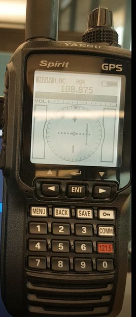
RF Carrier                                                                                                                                         DDM = V90 - V150
    Source                                    fc-90   fc+90
                 20% Modulation Depth                                                                                                    V90
                                                               f (Hz)
     RF Power                        fc-150              fc+150
                                                  Fc                   Antenna Array #1                                                                       DDM < 0
     Amplifier                                                                                                                  90 Hz      Bridge
                       90 Hz                                                                                                    Filter     Rectifier
                                                 CSB
                       Mod 20%                                                                                 AM
                                                                                                  Amplifier                                            Flag
                                                                                                               Demod                                          DDM = 0
                                                                                                                               150 Hz      Bridge
                       150 Hz                                                                                                  Filter      Rectifier
                       Mod 20%                   SBO
                                                                                                                                         V150
                 20% Modulation Depth fc-90             fc+90          Antenna Array #2                                                                       DDM > 0
                                                                                                                                                              Instrument
                                                                  f (Hz)                                                                                      Mechanics

                                                                                                                                                        CDI Needle Positions
                                   fc-150                     fc+150

                    ILS Transmitter                                                                                         ILS Receiver

Figure 2: Block diagram of ILS transmitter and receiver describing the process of generation and reception of ILS signal along with waveforms
at each stage.

2      Background                                                                         2.1     Instrument Landing System (ILS)
                                                                                          The first fully operational ILS was deployed in 1932 at the
Approach systems enable pilots to land airplanes even in ex-                              Berlin Tempelhof Central Airport, Germany. ILS enables the
treme weather conditions and are classified into non-precision                            pilot to align the aircraft with the centerline of the runway
and precision approach systems based on the accuracy and                                  and maintain a safe descent rate. ITU defines ILS [28] as “a
type of approach guidance provided to an aircraft. Non-                                   radio navigation system which provides aircraft with hori-
precision approach systems provide only horizontal or lateral                             zontal and vertical guidance just before and during landing
guidance (heading/bearing). Examples of non-precision ap-                                 and at certain fixed points, indicates the distance to the refer-
proach systems are VHF Omnidirectional Range (VOR) [58],                                  ence point of landing”. Autopilot systems on some modern
Non-Directional Beacon (NDB) [57], and satellite systems                                  aircraft [49] use ILS signals to execute a fully autonomous
such as GPS. With the development of precision approach                                   approach and landing, especially in low visibility settings.
systems, the use of non-precision approach systems such as                                ILS (Figure 1) comprises of three independent subsystems:
VOR and NDB has significantly decreased today. Precision                                  i) localizer, (ii) glideslope and iii) marker beacons. The lo-
approach systems provide both horizontal (heading/bearing)                                calizer and the glideslope guide the aircraft in the horizontal
as well as vertical (glide path) guidance to an approaching                               and vertical plane respectively. The marker beacons act as
aircraft. The Instrument Landing System (ILS) is the most                                 checkpoints that enable the pilot to determine the aircraft’s
commonly deployed precision approach system in use to-                                    distance to the runway. ILS has three operational categories:
day. Other examples of precision approach systems include                                 i) CAT I, ii) CAT II and, iii) CAT III. CAT III further has three
Microwave Landing System (MLS), Transponder Landing                                       sub-standards IIIa, IIIb and, IIIc. These operational categories
System (TLS), Ground Based Augmentation Landing System                                    are decided based on ILS installations at the airport 1 and is
(GLS), and Joint Precision Approach and Landing System                                    independent of the receiver on the aircraft. With the advent of
(JPALS). It is important to note that these alternate landing                             GPS and other localization technologies, the marker beacons
systems fundamentally still use existing ILS concepts and                                 are less important today and increasingly obsolete. However,
equipment mostly in scenarios where ILS is unavailable. For                               the localizer and the glideslope play a major role in an air-
example, TLS enables precision landing guidance in places                                 craft’s safe landing today and is expected to remain so for
where the terrain is uneven, and the ILS signal reflections off                           many years.
the ground cause undesirable needle deflections by emulating                              2.1.1    ILS Signal Generation
the ILS signals using only one base tower (in contrast to two
for ILS) whose placement allows more flexibility. However,                                ILS signals are generated and transmitted such that the waves
TLS still leverages the same fundamental concepts of ILS. In                              form a specific radio frequency signal pattern in space to cre-
short, ILS plays a key, de-facto role in providing precision                              ate guidance information related to the horizontal and vertical
landing guidance at the majority of airports today and it is,                                1 Procedures for the Evaluation and Approval of Facilities for Special
therefore, essential to evaluate its resilience to modern-day                             Authorization Category I Operations and All Category II and III Operations
cyber-physical attacks.                                                                   http://fsims.faa.gov/wdocs/Orders/8400_13.htm

USENIX Association                                                                                               28th USENIX Security Symposium                                359
positioning. ILS signal generators leverage space modulation at specific heights defined by the glide-path angle suitable for
i.e., use multiple antennas to transmit an amplitude modulated that particular airport’s runway. In contrast to the localizer, the
radio frequency signals with various powers and phases. The glideslope produces the signal pattern in the airspace based on
transmitted signals combine in the airspace to form signals the sum of the signals received from each antenna via the di-
with different depths of modulation (DDM) at various points rect line-of-sight path and the reflected path. The mixing of the
within the 3D airspace. Each DDM value directly indicates a CSB and SBO signals results in a pattern in which the 90 Hz
specific deviation of the aircraft from the correct touchdown component of the signal predominates in the region above
position. For example, the signals combine in space to pro- the glide-path while the 150 Hz prevails below the glide-path.
duce a signal with zero difference in the depth of modulation The glideslope uses carrier frequencies between 329.15 MHz
(DDM) along the center-line of the runway. It is important to and 335.0 MHz, and the antenna tower is located near the
note that unlike traditional modulation techniques where the touchdown zone of the runway. Typically, the center of the
modulation occurs within the modulating hardware, in space glide-slope defines a glide path angle of approximately 3◦ .
modulation, the signals mix within the airspace. For every localizer frequency, the corresponding glideslope
The process of generating the localizer and glideslope sig- frequency is hardcoded i.e., the localizer-glideslope frequen-
nals ( Figure 2 ) are similar with differences mainly in the cies occur in pairs and the instrument automatically tunes
carrier frequency used and how they are combined in space to the right glideslope frequency when the pilot tunes to a
to provide the relevant guidance information. The carrier sig- specific runway’s localizer frequency.
nal is amplitude modulated with 90 Hz and 150 Hz tones
2.1.2 ILS Receiver
to a certain depth of modulation. The depth of modulation
or modulation index is the measure of the extent of ampli- The combined signals received at the aircraft are amplified,
tude variation about an un-modulated carrier. The depth of demodulated, and filtered to recover the 90 Hz and 150 Hz
modulation is set at 20% and 40% respectively for localizer components. A bridge rectifier is used to convert the ampli-
and glideslope signals. The output of both the 90 Hz and 150 tude of the recovered tones to DC voltage levels. The DC
Hz modulator is then combined to yield two radio frequency voltage output is directly proportional to the depth of the
signals: a carrier-plus-sidebands (CSB) and a sidebands-only modulation of the 90 Hz and 150 Hz tones–a direct measure
(SBO) signal. The names of the signal directly reflect their of the dominating frequency signal. The DC voltage causes
spectral energy configuration with the CSB containing both the course deviation indicator needle to deflect based on the
the sideband energy and the assigned carrier frequency while difference in the depth of the modulation of the two tones
in the SBO signal the carrier frequency component is sup- thereby precisely indicating the aircraft’s lateral and vertical
pressed. The CSB and SBO signals are subjected to specific deviation from approach path.
phase shifts before being transmitted. The phase shifts are For example, an aircraft that is on-course will receive both
carefully chosen such that when the CSB and SBO signals 90 and 150 Hz signals with the same amplitude, i.e., equal
combine in space, the resulting signal enables the aircraft depth of modulation and will result in zero difference in the
to determine its horizontal and vertical alignment with the depth of modulation and therefore cause no needle deflections.
approach path. However, an aircraft that is off-course and not aligned with the
approach path will receive signals with a non-zero difference
Localizer. The localizer subsystem consists of an array of in the depth of modulation resulting in a corresponding de-
multiple antennas that emit the CSB and SBO signals such flection of the needle. The instruments are calibrated to show
that the 150 Hz modulation predominates to the right of the full scale deflection if DDM > 0.155 or DDM < −0.155
runway centerline and the 90 Hz signal prevails to the left. for localizer and if DDM > 0.175 or DDM < −0.175 for
In other words, if the flight is aligned to the right of the run- glideslope [20]. These values correspond to 2.5◦ offset on
way during the approach, the 150 Hz dominant signal will the left side of the runway, 2.5◦ offset on the right side of the
indicate the pilot to steer left and vice versa. The antenna runway, 0.7◦ offset above the glide path angle and 0.7◦ below
array of the localizer is located at the opposite end (from the the glide path angle respectively.
approach side) of the runway. Each runway operates its lo-
calizer at a specific carrier frequency (between 108.1 MHz to 2.2 Typical Approach Sequence
111.95 MHz) and the ILS receiver automatically tunes to this
frequency as soon as pilot inputs the runway identifier in the Pilots use aeronautical charts containing vital information
cockpit receiver module. Additionally, the runway identifier about the terrain, available facilities and their usage guidelines
is transmitted using a 1020 Hz morse code signal over the throughout a flight. Approach plates are a type of navigation
localizer’s carrier frequency. chart used for flying based on instrument readings. Every
pilot is required to abide by the routes and rules defined in
Glideslope. The glideslope subsystem uses two antennas an approach plate unless ordered otherwise by the air traffic
to create a signal pattern similar to that of the localizer except controller. The approach plate contains information like ac-
on a vertical plane. The two antennas are mounted on a tower tive localizer frequency of the runway, the runway identifier
360 28th USENIX Security Symposium USENIX AssociationILS Receiver DDM = VAT90 -VAT150
VAT90
SAT90
Bridge VAT90
SLOC Filter 90Hz Rectifier
+ Demod
Filter 150Hz Bridge
Rectifier VAT150
VAT150 OffsetAT = 0.5
SLOC+AT
SAT150 OffsetLOC = 0
SAT
Figure 3: Schematic of the overshadow attack. The attacker’s signal has a preset DDM corresponding to 0.5◦ to the right of the runway.
Attacker’s signal overshadows the legitimate signal. The blue line represents the needle position without attack.
in Morse code, glideslope interception altitude, ATC tower single-tone attack is a special attack where it is sufficient for
frequencies, and other information crucial for a safe landing. the attacker to transmit a single frequency tone signal at a
Once the pilot receives the clearance to land at an assigned specific signal strength (lower than the legitimate ILS signal
runway, the pilot enters the localizer frequency associated strength) to interfere and control the deflections of the course
with the designated runway and enters the course of the run- deviation indicator needle.
way into the auto-pilot. Note that the localizer and glides- Attacker model. We make the following assumptions re-
lope frequencies occur in pairs and therefore the pilot does garding the attacker. Given that the technical details of ILS
not have to manually enter the corresponding glideslope fre- are in the public domain, we assume that the attacker has
quency. When the pilot intercepts the localizer, the course complete knowledge of the physical characteristics of ILS
deviation indicator needle is displayed on the cockpit. The signals e.g., frequencies, modulation index etc. We also as-
pilot then verifies whether the receiver is tuned to the right sume that the attacker is capable of transmitting these radio
localizer by confirming the runway identifier which is trans- frequency signals over the air. The widespread availability of
mitted as morse code on the localizer frequency. For example, low-cost (less than a few hundred dollars) software-defined
for landing on runway 4R (Runway Ident - IBOS) at Logan radio platforms has put radio transmitters and receivers in the
International Airport, Boston, the pilot will tune to 110.3 MHz hands of the masses. Although not a necessary condition, in
and will verify this by confirming the Morse code: .. / --... / the case of single-tone, the knowledge of the flight’s approach
--- / ... Based on the deviation of the aircraft from the runway path, the airplane’s manufacturer and model will allow the
and the approach angle, the indicator will guide the pilot to attacker to significantly optimize their attack signal. We do
appropriately maneuver the aircraft. Modern autopilot sys- not restrict the location of the attacker and discuss pros and
tems are capable of receiving inputs from ILS receivers and cons of both an on-board attacker as well as a attacker on the
autonomously land the aircraft without human intervention. ground.
In fact, pilots are trained and instructed to trust the instru-
ments more than their intuition. If the instruments ask them to 3.1 Overshadow attack
fly right, the pilots will fly right. This is true specifically when The overshadow attack is an attack where the attacker trans-
flying in weather conditions that force the pilots to follow the mits specially crafted ILS signals at a power level such that
instruments. Detecting and recovering from any instrument the legitimate signals get overpowered by the attacker’s signal
failures during crucial landing procedures is one of the tough- at the receiver. The main reason why such an attack works
est challenges in modern aviation. Given the heavy reliance is that the receivers “lock” and process only the strongest
on ILS and instruments in general, malfunctions and adversar- received signal. Figure 3 shows how the attacker’s fake ILS
ial interference can be catastrophic especially in autonomous signal completely overshadows the legitimate ILS signal re-
approaches and flights. In this paper, we demonstrate vul- sulting in the deflection of the CDI needle. We note that the
nerabilities of ILS and further raise awareness towards the attacker signal can be specially crafted to force the CDI nee-
challenges of building secure aircraft landing systems. dle to indicate a specific offset as demonstrated in Section 4.2.
3 Wireless Attacks on ILS
Attack Signal Generation. Recall that the ILS receiver on-
We demonstrate two types of wireless attacks: i) Overshadow board receives a mix of the transmitted CSB and SBO signals
attack and ii) Single-tone attack. In the overshadow attack, that contain the 90 and 150 Hz tones (Figure 2). The ampli-
the attacker transmits pre-crafted ILS signals of higher signal tude of received 90 and 150 Hz tones depends on the position
strength; thus overpowering the legitimate ILS signals. The of the aircraft relative to the runway and its approach path
USENIX Association 28th USENIX Security Symposium 361fc-150 fc+150
RF Source
fc-90 fc+90 90 Hz
f (Hz)
Amplitude
fc-90 fc+90 Fc
On the right side
+ Modulator
RF Source fc-90 fc+90
fc-150 Fc fc+150 150 Hz
CSB Signal f (Hz) fc-90 fc+90 f (Hz)
RF Source
fc-150 Fc fc+150
+ Carrier
fc-150 Fc fc+150 108.1-111.95MHz
fc-90 fc+90
On the center-line
fc-150 fc+150 fc-90 fc+90
f (Hz)
SBO Signal
Figure 5: Signal generator used for generating the required attack
Localizer Tx
fc-150Fc fc+150 signal with specific amplitudes of the 90 Hz and 150 Hz components
On the left side
3.2 Single-tone attack
Figure 4: Frequency domain representation of the received signal Single-tone attack is an attack where the attacker transmits
showing the amplitudes of the sidebands as observed at various
only one of the sideband tones (either the 90 Hz or the 150 Hz)
lateral offsets
to cause deflections in the course deviation indicator needle.
In contrast to the overshadow attack, single-tone attack does
not require high powered spoofing signals. Recall that the
aircraft’s horizontal and vertical offset is estimated based on
angle. For example, as shown in Figure 4, the 90 Hz tone will the difference in the depth of the modulation of the 90 Hz and
dominate if the aircraft is offset to the left of the runway and the 150 Hz tones. As indicated in Figure 4, depending on the
the 150 Hz dominates to the right. Similarly, for glideslope, offset either of the frequency tones dominates. In the case of
the 90 Hz tone dominates glide angles steeper than the rec- an overshadow attack, the spoofing signal was constructed
ommended angle, and the 150 Hz tone dominates otherwise. with all the necessary frequency components. However, in
Both 90 and 150 Hz will have equal amplitudes for a perfectly the single-tone attack, the attacker aims to interfere with only
aligned approach. Therefore, to execute an overshadow at- one of the two sideband frequencies directly affecting the
tack, it is sufficient to generate signals similar to the received estimated offset.
legitimate ILS signals and transmit at a much higher power
as compared to legitimate ILS signals. In other words, the Attack Signal Generation. The working of the single-tone
attacker need not generate CSB and SBO signals separately; attack is shown in Figure 6. The legitimate localizer signal’s
instead can directly transmit the combined signal with appro- spectrum contains the carrier and both the sideband tones of
priate amplitude differences between the 90 and 150 Hz tones. 90 Hz and 150 Hz. As described previously, the amplitudes
The amplitude differences are calculated based on the offset of the sideband tones depend on the true offset of the aircraft.
the attacker intends to introduce at the aircraft. The attacker’s In a single-tone attack, the attacker generates only one of the
signal (Figure 5) is generated as follows. There are two tone two sideband tones i.e., fc ± 90 or fc ± 150 with appropri-
generators for generating the 90 and the 150 Hz signals. It is ate amplitude levels depending on the spoofing offset (e.g.,
important to enable configuration of each individual tone’s left or right off the runway) introduced at the aircraft. For
amplitude to construct signals with a preset difference in the example, consider the scenario where the attacker intends to
depth of modulation corresponding to the required deviation force the aircraft to land on the left of the runway with an
to spoof. The tones are then added and amplitude modu- offset of 0.5◦ . The legitimate difference in depth of modula-
lated using the runway’s specific localizer or glideslope fre- tion will be zero as the aircraft is centered over the runway.
quency. Recall that the amplitude differences i.e., difference To cause the aircraft to go left, the attacker must transmit
in depth of modulation (DDM) between the two tones directly signals that will spoof the current offset to be at the right side
corresponds to the required offset to spoof. In the absence of the runway. As shown in Figure 4, the 150 Hz component
of the adversarial signals the estimated DDM = VLOC90 − dominates in the right side of the runway approach and there-
VLOC150 . In the presence of the attacker’s spoofing signals, fore the attacker needs to transmit the fc ± 150 signal with an
the estimated DDM = [VLOC90 +VAT 90 ] − [VLOC150 +VAT 150 ]. appropriate amplitude to force the aircraft to turn left. For the
Since VAT 90 >> VLOC90 and VAT 150 >> VLOC150 , the resulting specific example of 0.5◦ offset, the amplitude of the fc ± 150
DDM = VAT 90 −VAT 150 . Thus by manipulating the amplitude component should be such that the difference in the depth of
differences between the transmitted 90 Hz and 150 Hz tones, modulation equals 0.03 [20].
the attacker can acquire precise control of the aircraft’s course Notice that the single-tone attack signal is similar to
deviation indicator and the aircraft’s approach path itself. a double-sideband suppressed-carrier signal which is well-
362 28th USENIX Security Symposium USENIX Associationf (Hz) ILS Receiver DDM = VLOC90 -VAT150
fc-90 fc+90 VLOC90
SAT90
fc-150 Fc fc+150 Bridge VAT90
SLOC Filter 90Hz Rectifier
+ Demod
Filter 150Hz Bridge
Rectifier VAT150
VAT150 DDMAT > -0.155
f (Hz) SLOC+AT
t SAT150 DDMLOC = 0
SAT fc-150 fc+150
Figure 6: Schematic of the single-tone attack. Attacker constructs a DSB-SC signal without the 90 Hz component and the carrier. The blue
line represents the needle position without the attack
Attacker control unit
RF Source DSB-SC Location Data
Spoofing Legitimate LOC
90 Hz or 150 Hz Modulator
zone signal GS USRP 1
90 Hz 90 Hz detector generator
RF Source Offset Attacker
f (Hz) LOCAT
Carrier correction signal
fc-90/150 fc+90/150 GSAT USRP 2 Handheld
108.1-111.95MHz algorithm generator
Instrument Aviation
values Receiver
Figure 7: Single-tone attack signal generator with a DSB-SC mod-
ulator
Figure 8: Schematic of the experiment setup used for evaluating the
attacks on ILS. The attacker control unit interfaces with the simula-
tor and USRP B210s. A flight yoke and throttle system is connected
known to be spectrally efficient than the normal amplitude to the machine running X-Plane flight simulator software. Attacker
modulation signal. Specifically, it is possible for the attacker control unit interfaces with the flight simulator over a UDP/IP net-
to reduce the required power to almost 50% of the overshadow work.
attack as there is no need to transmit the carrier signal and one
of the sideband signals. One of the important limitations of
the single-tone is the effect of the attacker’s synchronization 4.1 Experimental Setup
with the legitimate signal. To precisely control the spoofing
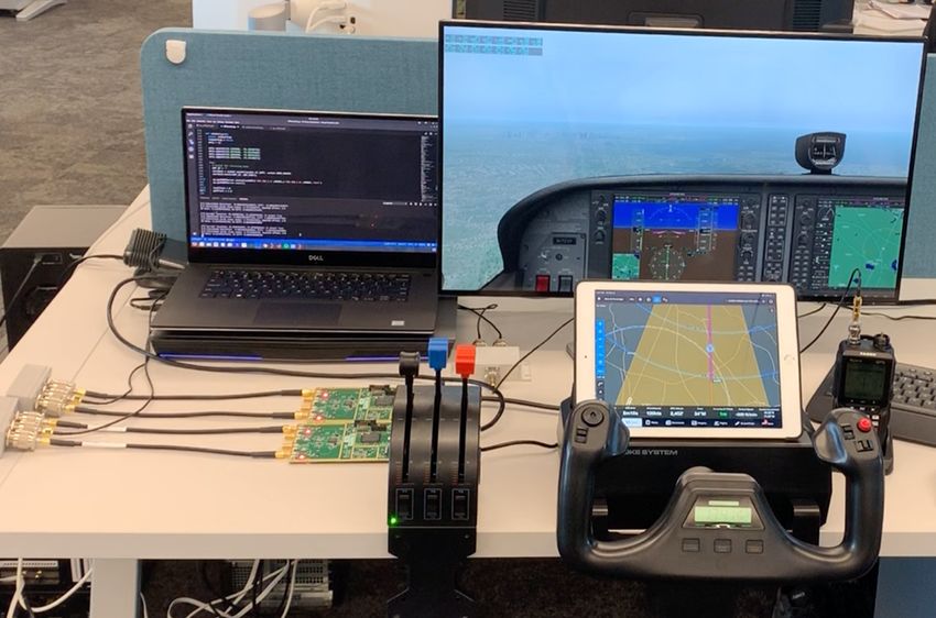
Our experimental setup is shown in Figure 8 and Figure 9.
offset, the attacker needs to coarsely control the spoofing sig-
The setup consists of four main components: i) X-Plane 11
nal such that the phase difference between the attacker and
flight simulator, ii) attacker control unit, iii) software-defined
the legitimate signals remain constant throughout the attack.
radio hardware platforms (USRP B210s) and iv) commercial
We evaluate and show in Section 4.3.1 the effect of phase
aviation grade handheld navigation receiver. We use X-Plane
synchronization on this attack. Additionally, the spectral effi-
11 flight simulator to test the effects of spoofing attack on
ciency of the single-tone attack can be exploited to execute
the ILS. X-Plane is a professional flight simulator capable
a low-power last-minute denial of service on the ILS system.
of simulating several commercial, military, and other aircraft.
This is specifically dangerous while an aircraft is executing
X-Plane can also simulate various visibility conditions and
an auto-pilot assisted approach. The block diagram of the
implements advanced aerodynamic models to predict an air-
single-tone attack signal generator is shown in Figure 7.
craft’s performance in abnormal conditions. It is important to
note that X-Plane qualifies for FAA-certified flight training
4 Implementation and Evaluation of Attacks hours when used with computer systems that meet the FAA’s
minimum frame rate requirements. The certified versions of
In this section, we demonstrate the feasibility and evaluate the the software are used in numerous pilot training schools. X-
effectiveness of the attack with the help of both simulations Plane allows interaction with the simulator and instruments
and actual experiments conducted using commercial aviation- through a variety of mobile apps and UDP/IP networks. This
grade receivers and an advanced flight simulator qualified for feature allowed us to manipulate the instrument readings for
FAA certification. evaluating our ILS attacks. Additionally, X-Plane has autopi-
USENIX Association 28th USENIX Security Symposium 363D
Attacker control unit X-Plane flight Simulator
22km
B
9.45km 9.45km 9.45km
Handheld MILTT NABBO WINNI
Rx
F
A 37km
C
USRP 1
USRP 2
E
Figure 10: The spoofing zone is defined by points B, C, D, and
E. WINNI, NABBO, and MILTT are the waypoints for the final
approach as published for a mid-sized airport. The spoofing zone has
Figure 9: Photo of the experiment setup. a wide aperture as the air-traffic controller can vector in the aircraft
onto the final approach in multiple ways.
lot and AI-based autoland features which we leverage in our
experiments. In other words, X-Plane contains all the features 4.1.1 Spoofing Zone Detection
and flexibility to evaluate our proposed attacks in a close to
the real-world setting. The second component of our setup is The spoofing zone detection algorithm enables automated
the attacker control unit module which takes the location of and timely triggering of the spoofing signal. One of the key
the aircraft as input from X-Plane and generates signals for requirements of the zone detector is to trigger the spoofing
the attack. The module is also responsible for manipulating signals without causing any abrupt changes to the instrument
X-Plane’s instrument panel based on the effect of the spoof- readings; thereby avoiding detection by the pilots. The spoof-
ing signal on the receiver. The attacker control unit module ing region is shaped like a triangle following the coverage of
is a laptop running Ubuntu and contains four submodules: the localizer and glideslope signals. For example, the localizer
spoofing zone detector, offset correction algorithm, legitimate covers 17.5◦ on either side of the extended runway centerline
signal generator, and attacker signal generator. The spoofing and extends for about 35 km beyond the touchdown zone. Fig-
zone detector identifies whether an aircraft is entering its first ure 10 shows the zone measurements. The attacker signals
waypoint of the final approach and triggers the start of spoof- are triggered when the aircraft approaches the shaded region.
ing. The spoofing zone detector plays an important role in The shaded region is decided based on the final approach pat-
timely starting of the spoofing attack so as to prevent any terns for a specific runway. We used even-odd algorithm [27]
abrupt changes in the instrument panel and therefore avoid for detecting the presence of the aircraft within this spoofing
suspicion. The offset correction algorithm uses the current zone. Absolute locations cannot be used as aircraft enter the
location of the aircraft to continuously correct its spoofing final approach path in many different ways based on their
signals taking into consideration aircraft’s corrective actions. arrival direction and air traffic controller instructions. The
Note that the location data received from X-Plane can be even-odd algorithm is extensively used in graphics software
analogous to receiving the location data through ADS-B sig- for region detection and has low computational overhead. The
nals [29] in the real world. The output of the offset correction attacker automatically starts transmitting the signals as soon
algorithm is used to generate fake ILS signals. We also gener- as the aircraft enters the spoofing region from the sides and
ate legitimate signals to evaluate the effect of overshadow and the needle is yet to be centered. This prevents any sudden
single-tone attacks. We use two USRP B210s [2], one each noticeable jumps thus allowing a seamless takeover.
for transmitting legitimate ILS signals and attacker signals.
4.1.2 Offset correction algorithm
We conducted the experiments in both wired and wireless set-
tings. For the experiments conducted in wireless settings, the The attacker’s signals are pre-crafted to cause the aircraft
receiver was placed at a distance of 2 meters from the trans- to land with a specific offset without being detected. The
mitter. Northeastern University has access to a Department of pilot or the autopilot system will perform course correction
Homeland Security laboratory which provides RF shielding maneuvers to align with the runway centerline based on the
thus preventing signal leakage. This is necessary as it is ille- instrument readings. At this point, the instruments will contin-
gal to transmit ILS signals over the air. We use two different uously indicate the spoofed offset irrespective of the aircraft’s
ILS receivers, a Yaesu FTA-750L [10] and a Sporty’s SP-400 location and maneuvers raising suspicion of an instrument
Handheld NAV/COM Aviation [3] to evaluate the attacks. failure. To prevent this, we developed a real-time offset correc-
364 28th USENIX Security Symposium USENIX AssociationAlgorithm 1 Offset correction algorithm.
1: procedure G ETA NGLE D IFFERENCE
2: ∠DAC ← TargetedLocalizerO f f set
B
3: ∠BAC ← GetAngle(location)
4: di f f erence ← ∠DAC − ∠BAC
5: return di f f erence
A 6: procedure C ALCULATE DDM
C
7: di f f erence ← GetAngleDi f f erence
8: ddm ← (0.155 ∗ di f f erence)/2.5
D
9: AT 90 ← 0.2 + (ddm)/2
10: AT 150 ← 0.2 − (ddm)/2
11: ChangeAmplitude(AT 90, AT 150)
Figure 11: Offset correction algorithm takes into account aircraft’s
current position to calculate the difference in the spoofed offset and
the current offset.
4.1.3 Setup Validation
We verified the working of our experimental setup as fol-
lows. First, we ensure consistency between the CDI needle
displayed on the flight simulator and the handheld receiver.
tion and signal generation algorithm that crafts the spoofing
To this extent, we disabled the attacker signal and output only
signals based on the aircraft’s current location in real-time.
the legitimate signal to the handheld receiver based on the
The attacker can use the GPS coordinates if present inside the
aircraft’s location obtained from X-Plane. We manually val-
aircraft or leverage the ADS-B packets containing location
idated that the alignment shown on the handheld receiver
information on the ground. We explain the offset correction
is the same as that of the flight simulator throughout the fi-
algorithm using Figure 11. Consider an aircraft at point B,
nal approach. The uploaded attack demonstration video 2
cleared to land and entering the spoofing zone. The air-traffic
also contains this validation for reference. We conducted the
controller instructs the aircraft to intercept point C on the ex-
same experiment over the air in a controlled environment and
tended runway centerline. Assuming that the attacker’s spoof-
verified consistency between the handheld receiver and the
ing signal contains a pre-crafted offset to the left of the run-
flight simulator cockpit. Second, we test our offset correction
way forcing the aircraft to follow path DA instead of CA. The
algorithm by maneuvering (swaying) the aircraft during its
offset correction module computes the current offset of the
final approach. During this experiment, the offset correction
aircraft with respect to the centerline and subtracts the current
algorithm should account for the maneuvers and generate cor-
offset from the spoofed offset to estimate the desired change
responding ILS signals to the handheld receiver. We ensure
in the course. Thus, the correction ∆ required to be introduced
the correctness of the algorithm by validating the consistency
is the difference between required offset angle ∠DAC and
between the handheld receiver’s CDI needle and the flight
the current offset angle ∠BAC. Note that offsets to the left of
simulator cockpit. Note that we do not update the flight simula-
centerline are considered negative offsets and offsets to the
tor’s instrument readings for this experiment and the readings
right are considered positive offsets. The current offset θ can
displayed in the simulator cockpit are only because of the sim-
be estimated using θ = tan− 1[(mCA −mBA )/(1+mBA ∗mCA )],
ulator software engine. Finally, we validate the spoofing zone
where m is the slope. mCA is typically hardcoded and is spe-
detector algorithm by entering the final approach from various
cific for each runway. mBA can be estimated using the lon-
directions and checking the trigger for beginning the spoofing
gitude and latitudes of the touchdown point and the current
attack. We are now ready to perform our attack evaluations.
location of the aircraft. Now, the correction ∆ is converted to
the respective difference in depth of modulation value using 4.2 Evaluation of Overshadow Attack
the formula DDM = (DDM f ullscale ∗ ∆)/2.5, where 2.5 is the We evaluate the effectiveness of overshadow attack as follows.
angle that results in full-scale deviation and DDM f ullscale is We leverage the autopilot and autoland feature of X-Plane to
the difference in depth of modulation that causes full-scale analyze the attack’s effects avoiding any inconsistency that
deviation. The amplitude of the individual 90 and 150 Hz might arise due to human error. We configured X-Plane to
components is estimated using the formula 0.2 + (DDM/2) land on the runway of a midsized airport in the US. This
and sent to the signal generator module which then trans- configuration is analogous to the pilot following approach
mits the required signal. Note that the value 0.2 comes from instructions from the air-traffic controller. As soon as the
the legitimate signal’s depth of modulation. The algorithm aircraft entered the spoofing zone, the spoofing signals were
was implemented on a laptop running Ubuntu and took less transmitted along with the legitimate signals. The spoofing
than 5 ms on average to compute the offsets. The complete
algorithm is shown in Algorithm 1. 2 Video demonstration of the attack https://youtu.be/Wp4CpyxYJq4
USENIX Association 28th USENIX Security Symposium 365Touchdown offset (meters)
1.5
52.1 400 200 0 200 400 600 800 1000
Spoofed localizer offset (degrees)
1.0 Touchdown zone
35.2
0.5
17.3
3.3 3.2 3.1 3.0 2.9 2.8
0.0 0
0.0
Spoofed glide path angle (degrees)
-17.9
4
0.5
-33.9
1.0
R
-51.7
Figure 13: Results of glideslope spoofing. 5 automated landings per
1.5 spoofed glideslope angle offset were executed and the touchdown
40 20 0 20 40 offset in meters beyond the touchdown zone was recorded.
Touchdown offset (meters)
ceiver. We observed that the spoofing signal caused the needle
Figure 12: Results of localizer spoofing. 5 automated landings per to deflect to the configured offset. However, the needle was
spoofed localizer offset were executed and the touchdown offset in
not as stable as in the overshadow attack and displayed minor
meters from the runway centerline was recorded.
oscillations. This is because the specific attack is sensitive to
carrier phase oscillations and therefore must be accounted for
signals were generated to fake various vertical and horizon- to avoid detection. A significant advantage of this attack is
tal offsets. Note that the spoofing signals were generated in the power required to cause needle deflections as the attacker
real-time based on the current position of the aircraft. For the only transmits one of the sideband components without the
localizer (horizontal offset), spoofing signals corresponding carrier. This gives an almost 50% increase in power efficiency
to 0.5, 1.0, and 1.5◦ offset on both sides of the runway were and therefore can act as a low-power last-minute denial of
generated. The spoofing glideslope angles were between 2.8◦ service attack in case the attacker is unable to establish full
and 3.3◦ . For each spoofing angle and offset, we performed synchronization with the legitimate signal. In the following
five automated landings and the results are shown in Fig- sections, we evaluate the effect of phase synchronization on
ure 12 and Figure 13. Throughout the attack, we continuously the single-tone attack and develop a real-time amplitude scal-
monitored the path of the aircraft using Foreflight 3 , a pop- ing algorithm that can counter the phase oscillations.
ular app used both by aviation enthusiasts and commercial 4.3.1 Effect of Phase Synchronization
pilots as well as X-Plane’s own interfaces. We did not observe
any abrupt changes in the readings and observed a smooth Recall that the single-tone attack signal is similar to a conven-
takeover. The aircraft landed with an 18 m offset from the run- tional double-sideband suppressed-carrier (DSB-SC) signal.
way centerline for a spoofing offset of just 0.5◦ . Note that this It is well known that one of the drawbacks of a DSB-SC com-
is already close to the edge of the runway and potentially go munication system is the complexity of recovering the carrier
undetected by both the air-traffic controllers as well as pilots signal during demodulation. If the carrier signal used at the
onboard, especially in low visibility conditions. In the case receiver is not synchronized with the carrier wave used in
of glideslope, a shift in the glide path angle by 0.1◦ i.e., 2.9◦ the generation of the DSB-SC signal, the demodulated signal
glide path angle instead of the recommended 3◦ , caused the will be distorted. In the scenario of the single-tone attack, this
aircraft to land almost 800 m beyond the safe touchdown zone distortion can potentially result in changes in the difference
of the runway. We have uploaded a video demonstration of in the depth of modulation estimates causing the needle to
the attack for reference ( https://youtu.be/Wp4CpyxYJq4 oscillate. We simulated the effect of phase synchronization
). on the single-tone attack effectiveness and present our results
in Figure 14 and Figure 15. We generated the single-tone
4.3 Evaluation of Single-tone Attack attack signal to cause full-scale deviation i.e., & 2.5◦ for lo-
We evaluate the effectiveness and feasibility of the proposed calizer and & 2.5◦ for the glideslope while perfectly in sync
single-tone attack using the experimental setup described with the legitimate carrier signal. We observe that the phase
in Section 4.1. Recall that in the single-tone attack, the at- difference causes the resultant offset to change. We also noted
tacker transmits only one of the sideband tones (either the an uncertainty region around the 90◦ and 270◦ phase differ-
fc ± 90 or the fc ± 150 Hz) to cause deflections in the course ence region. This is due to the dependency in a DSB-SC
deviation indicator needle. We implemented the attack by con- system [26] between the carrier phase difference φ and the
figuring one of the USRPs (attacker) to transmit the sideband resulting distortion at the output which is directly proportional
signals and observed its effect on the handheld navigation re- to the cosφ. Therefore, at angles around 90◦ and 270◦ , there
is an uncertainty region for the resulting offset. However, in
3 Advanced Flight Planner https://www.foreflight.com our experiments on the handheld receiver, we noticed that
366 28th USENIX Security Symposium USENIX Association3.8
3
3.6
2
Resultant glide path angle
3.4
Resultant offset
1
3.2
Localizer 150 Hz tone Glideslope 150 Hz tone
0 3.0
Localizer 90 Hz tone Glideslope 90 Hz tone
2.8
1
2.6
2
2.4
3
2.2
0 50 100 150 200 250 300 350 0 50 100 150 200 250 300 350
Phase difference in degrees Phase difference (degrees)
Figure 14: Comparison of calculated offset and the phase Figure 15: Comparison of calculated offset and the phase
difference for localizer difference for glideslope
although the needle oscillated, it was not as pronounced as
the simulation results indicate. One of the reasons is the rate
at which the sensor measurements are being calculated and in Figure 16 and Figure 17.
displayed on the screen. Additionally, the aircraft is in motion,
therefore, causing the phase differences to cycle more rapidly
than the display’s refresh rate. A knowledgeable attacker can 4.4 Comparison of Power Requirements
potentially leverage these properties to generate controlled
spoofing signals and succeed with an optimized transmission
power. One of the major advantages of the single-tone attack is the im-
provement over the power required to execute the attack, given
4.3.2 Real-time Amplitude Scaling sufficient knowledge and environmental conditions. In this
In the following, we propose and evaluate a strategy to counter section, we evaluate and compare the power requirements of
the effect of phase synchronization on the single-tone attack. the overshadow and the single-tone attacks. We note that the
It is clear that the phase differences cause the output to be absolute power profiles are specific for the handheld receivers
distorted. Besides the uncertainty region around the 90◦ and used in the experiments. The goal of the power comparison is
270◦ , it is possible to predict the phase given sufficient knowl- to verify whether there is indeed an improvement in terms of
edge such as aircraft speed, current location, and antenna attacker’s required transmission power. We present our results
positions. We assume such a motivated attacker for the single- in Figure 18 and Figure 19. Our evaluations show the required
tone attack evaluation in this section. It is also well known signal strength to successfully cause 0.5◦ and 0.1◦ deviation
that tightly controlling the phase of a signal is not trivial and in localizer and glideslope respectively. The received signal
therefore our algorithm proposes to manipulate the amplitude strength profile is shown in blue acts as a reference for the
of the attacker signal instead of the phase. Changing the am- attacker based on which the attacker can compute its required
plitude of the attacker signal will compensate for the effect power to transmit the spoofing signals. We performed the ex-
of phase on the signal at the receiver and we call this “real- periment by transmitting the signals to the handheld receiver
time amplitude scaling” algorithm. The algorithm itself is and observing the success of the attack (needle indicating
inspired from prior works on amplitude scaling for DSB-SC the intended offset). The values are a result of over 400 trials
systems [26]. We use the distance between the transmitter with 95% confidence interval and we find that on an average
and the receiver to estimate the received phase of the signal the difference in power required reaches close to 20.53 dB
by measuring complete and incomplete wave-cycles. In the and 27.47 dB for the localizer and the glideslope respectively.
simulation, we then create an ILS signal with the necessary Thus, given sufficient knowledge of the scenario, a motivated
phase shift. We also create the attacker’s signal and add it attacker can execute the single-tone attack successfully and
to the legitimate signal to estimate the DDM. This allows with less power than the overshadow attack. We acknowledge
us to assess the impact of phase on the transmitted signal that the single-tone attack has its drawbacks as described
and use this information to calculate the amplitude that will previously, however, we note that given the low power re-
be required to counter the effects of phase. For example, if quirements, an attacker can exploit the single-tone attack to
the predicted phase offset is zero, then to spoof a certain off- cause a low-power denial of service attack. Such an attack,
set, the attacker needs to reduce the amplitude of its signal. especially in an aircraft’s final moments before landing can
We present the results of our amplitude scaling experiment be disastrous.
USENIX Association 28th USENIX Security Symposium 3671.0
0 Req Tx Power: Overshadow
Received Signal Strength
0.8 5 Req Tx Power: Single-tone Attack
Corrected 90 Hz amplitude
Signal Strength (dBm)
10
0.6
15
0.4
20
Offset 0.5
Offset 1.0
0.2 Offset 1.5 25
Offset 2.0
Offset 2.5 30
0.0
0 50 100 150 200 250 300 350 35
Phase difference (degrees)
0 1 2 3 4 5 6 7 8 9 10
Distance from Touchdown (Km)
Figure 16: Amplitude scaling algorithm evaluation localizer.
Amplitude required to compensate for the effect of phase
Figure 18: Comparison of required received signal strength
1.0 for attack methodologies for the localizer
Corrected 90 Hz amplitude
0.8
Req Tx Power: Overshadow
0 Received Signal Strength
0.6
Req Tx Power: Single-tone Attack
Offset 0.1
Signal Strength (dBm)
10
0.4 Offset 0.2
Offset 0.3
Offset 0.4 20
0.2 Offset 0.5
Offset 0.6
Offset 0.7 30
0.0
0 50 100 150 200 250 300 350
Phase difference (degrees) 40
Figure 17: Amplitude scaling algorithm evaluation glideslope. 50
0 1 2 3 4 5 6 7 8 9
Amplitude required to compensate for the effect of phase Distance from Touchdown (Km)
5 Discussion
Figure 19: Comparison of required received signal strength
Receiving antenna characteristics and location of the at- for attack methodologies for glideslope
tacker. The receiver hardware and its characteristics4 vary
depending on the type of aircraft it is mounted on. For ex-
ample, Cessna aircraft have their ILS antennas on the tail-fin that falls within the receiving lobe of the onboard antennas.
or the vertical stabilizer. We note that the same antenna is Attackers inside the plane will have to deal with signal atten-
typically used for a number of systems such as VOR, ILS, uation caused by the body of the aircraft itself and position
and DME; each signal arriving from a different direction. For the spoofing signal transmitter accordingly. A thorough inves-
commercial aircraft, the antennas are typically located on the tigation is required to fully understand the implications and
nose of the plane with a forward-looking single broad lobe feasibility of an on-board attacker and we intend to pursue
receiving beam pattern. Certain large aircraft, specifically the experiments as future work. The location of the attacker
those capable of landing with high nose attitude, the antennas plays a more significant role in the scenario of the single-tone
are located either on the underside or on the landing gear of attacker since the attacker has to carefully predict the phase
the aircraft itself 5 . The antenna equipment onboard plays an and accordingly manipulate the amplitude of the spoofing
important role in determining the optimum location of the signal. The problem of identifying optimum locations for the
attacker to execute the attack. The ideal location of an on- attack is an open problem very similar to the group spoofing
ground attacker is at a point along the centerline of the runway problem [56] proposed as a countermeasure for GPS spoofing
4 https://www.easa.europa.eu/certification-specifications/
attacks. In our context, the attacker has to identify locations
cs-23-normal-utility-aerobatic-and-commuter-aeroplanes
on the ground such that the phase difference between the legit-
5 https://www.casa.gov.au/sites/g/files/net351/f/_assets/ imate signal and the spoofing signal remains a constant along
main/pilots/download/ils.pdf the line of approach. Recall that in the single-tone attack, the
368 28th USENIX Security Symposium USENIX AssociationYou can also read