X-Band 4 x QTRM Plank Product Capability
←
→
Page content transcription
If your browser does not render page correctly, please read the page content below
X-Band 4 x QTRM Plank Product Capability
MA-100002
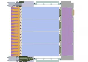
Description
The X-band Plank described below contains four Quad Transmit Receive Modules providing sixteen ports
which can be connected to individual antenna elements to form a 1-D phased array active antenna unit.
Three M2 threaded holes in the end of each QTRM facilitates the attachment of a quad antenna module.
Alternatively, equal length, low loss microwave cables can be used to connect to individual antenna
elements in which case the holes could be used to attach a plate fitted with four cables.
Provision for liquid cooling allows continuous transmission of long pulse widths at high duty cycles
through all sixteen elements simultaneously, thus creating a high power transmitter pulse at X-band.
A closed loop cooling system comprising of a fluid reservoir, pump and heat exchanger can be used to
pump the coolant through the Plank.
QTRM
• Common module ‘Building Block’
• 4-Channel integrated assembly comprising of DC, Logic CTRL/Interface & T/R Module
• Designed for high volume manufacture
• Minimal alignment, custom ATE for factory ‘calibration’Description The Plank is supplied from a single 28 volt DC supply and contains the necessary supply conditioning to power the four QTRM’s. A power-up sequence ensures that the input current surge is managed both within the individual QTRM’s and within the Plank so as to avoid overloading the primary 28 volt supply on switch-on. In addition, a half-duplex, asynchronous, RS485 bus allows communication to and from an external Beam Steering Computer (BSC) that provides control and monitoring of the Plank and its QTRM’s. The serial data takes the form of a number of messages assigned to either control the individual T-R elements or to retrieve information about their settings or health status. RF2M have developed a Graphical User Interface (GUI) to control and monitor the behaviour of the Plank and can be run from a laptop or desktop computer. Timing is provided by either an internal or external 100MHz clock and is selected via the micro-D connector. A transmitter power amplifier gating pulse must be provided to activate the PA power supplies just before the RF pulse arrives at the common RF I/O port. This is to ensure that any amplitude and phase transients caused by the PA’s turning on do not interfere with the integrity of the RF pulse. All subsequent timing within the plank is derived from this TX PA gating pulse leading edge. The plank may be driven with a CW signal for test purposes as internal modulation is provided. A scheduler mode can be selected which rapidly stores a maximum of sixteen, pre-determined beam steering coordinates. An external Beam Steer pulse must be provided by the BSC to step through the schedule to allow very fast beam switching. The QTRM’s are factory calibrated to minimise amplitude and phase variations over temperature and frequency, making them line-replaceable units. Additional calibration constants that are User system related can be uploaded to the QTRM’s via the RS485 serial data link. This product offering from RF2M Microwave provides the means to experiment with X-band phased array radar and to further develop a 2-D radar by stacking Planks up to eight deep. This product significantly reduces development time allowing customers to focus their valuable resources on radar signal processing and beam control. RF2M Microwave would welcome the opportunity to work with customers during their product development by providing technical support to customise an active antenna array solution.
Electrical Performance
Over TOP Unless Otherwise stated. Limits & Conditions are indicated values. Indicated
values given per channel unless otherwise stated.
                Parameter                Min.         Typ.       Max.       Units                       Conditions
                                                   Parameters: Transmit
 Centre Frequency                                     9.5                   GHz         See Note 1
 Operating BW                                          1                    GHz         See Note 1
 Input Return Loss                                    10                     dB         Common RF In/Out port
 Output Return Loss                                   10                     dB         Individual Antenna ports
 Pulse Width                               3                      100        μS         80μS at 30% Duty max.
 Duty Cycle                                5                      30          %         80μS at 30% Duty max.
 RS485 Serial Data bus                            Differential                          Asynchronous UART, half-duplex
 Data Control Rate                                    5.0                   Mbps
                                                                                        Gate TX PA on 2.6 μS before RF pulse,
 TX PA Gating Pulse                               Differential
                                                                                        target 1 μS
 Beam Steering Pulse                              Differential                          Triggers Beam Direction change
 No. of Stored Beam Settings                                      16                    Scheduler Mode
                                                                                        Time taken to re-load the Scheduler
 Beam Steer Data Transfer Time                                    350        μS
                                                                                        register
 Plank Input Voltage Range                26          +28         30        Volts
 Plank Input Current                                  8.5                   Amps        Average current @ 28v, 30% duty
 DC Input Consumption                                 238                   Watts       Average power @ 28v, 30% duty
 Beam former Insertion Loss                           13                     dB         To be confirmed
 Selectable Int. or Ext. Clock                        100                   MHz         ±20ppm LVDS
                                                   Parameters: Transmit
 TX Psat                                              8.5                 Watts(pk) 8.5Watts output per antenna port at Fo
 TX Input Power Level                                 +20         +23       dBm         For Psat Out.
 Spurious                                             -60                    dBc
 TX Phase Variation across pulse                      4.0                    deg        Across 80μS Pulse at 30% Duty
 TX Amplitude Variation across pulse                  0.5                    dB         Across 80μS Pulse at 30% Duty
 Harmonics                                            -20                    dBc
 TX Insertion Phase Balance                           ±15                    deg        Between any two channels. Target ±10
 TX Power Balance                                    ±2.0                    dB         Between any two channels. Target ±1
                                                    Parameters: Receive
 RX Output P1dB                                        -4                   dBm
 RX Gain                                              14                     dB         See Note (2) & (3)
 RX Input IP3                                          -8                   dBm
 RX Noise Figure                                                   4         dB         See Note (4). Target
Product Features
• RS485 Half-Duplex, 5.0 Mbps serial data bus for control and monitoring.
• Plank operating current and power supply health monitored and reported on request along
with health status of each QTRM
• Automatic shut-down of individual QTRM’s if their internal temperature reaches a critical limit
where damage could occur. Hysteresis applies.
• Positive supplies inhibited (with the exception of the digital control circuits) if negative supply
is lost
• Direction cosines used for beam steering
• QTRM’s respond to individual address or broadcast messages.
• Module position assignment
• Sequenced QTRM power-up timing based on module position address
• Ability to schedule up to 16 phase & amplitude settings for rapid beam switching
• Ability to disable internal modulation and apply externally
• Array CAL allows end-user to add additional TRU phase & amplitude calibration.
• Read-back of CAL phase & amplitude values for each TRU.
• Selection of internal/external Clock source to allow synchronisation of multiple QTRM’s.
• European Manufacture.
Mechanical
Approximate Size: 203mm(L) x 270mm(W) x 20mm(D) excluding connectors. See Note (5)
Approximate Mass: 1.2 Kg
RF Connectors: Male SMP shroud
DC Connector : 37-way Micro-D plug
Hydraulic Connectors : Staubli CGO 03 type, non-spill
Cooling Fluid : Glycol mix
Inlet Temperature : +48°C max.
Fluid Flow Rate : 1Litre/min
Outlet Temperature : approximately +58°C for an inlet temperature of +48°C
Pressure Drop : < 0.2 bar with a fluid flow rate of 1L/min
Environmental
Operating Ambient: -30 to +70°C.
Assumes Plank Fluid Inlet Temperature is in the range +10 °C to +48 °C
Storage: -40 to +85°C
MTBF : TBD
NOTES
(1) Limited by circulator specification and physical dimensions of the QTRM
(2) Up to 3dB reduction in useable attenuation range due to Calibration.
(3) Figure given for Ref Attenuator state, Ref Phase State and includes Beam former losses.
(4) N.F. given for Ref Attenuator state, Ref Phase State and includes Beam former losses.
(5) Dimension “D” is for Demo Unit only. Potential to reduce to 14.1mm for a practical AESA
configuration. See outline diagram in section 8 below.Functional Block Diagram
+v
e Bus to
Tx PA Gate -ve
QTRM's
+v
e Bus to Antenna Port 1
Beam Steer -ve
QTRM's
Antenna Port 2
+v
e Bus to QTRM A
RS485 ASYNC Antenna Port 3
-ve
Bus QTRM's
Antenna Port 4
Antenna Port 5
Antenna Port 6
QTRM B
Antenna Port 7
+28v Antenna Port 8
RF +6.0v
In/Out +28v Converters
+3.3v
Input & LDO's
+5.0v
Antenna Port 9
-6.0v
Converter Sync Antenna Port 10
Switch QTRM C
Logic Antenna Port 11
DRVR
Antenna Port 12
Monostable Antenna Port 13
100MHz Antenna Port 14
Div 100
Clock QTRM D
Antenna Port 15
Antenna Port 16
- Bus to
Int Clk Enable + QTRM's
-
Ext. 100MHz Clock
+
DC Pin-Out Connection’s (37-way Mirco-D)
Pin No. Description Pin No. Description Pin No. Description Pin No. Description
1 +28V 11(1) Ext_CLK +ve 21 +28V 31 Spare
2 +28V 12 Signal GND 22 PSU GND 32 Spare
3 PSU GND 13 Spare 23 PSU GND 33 -6V Flag
4 PSU GND 14 +28V Flag 24 ADDR_1 34 Pmon Flag
5 ADDR_0 15 +6V1 Flag 25 Tx PA Gate +ve 35 ICC_Mon
6 ADDR_2 16 +6V2 Flag 26 Signal GND 36 Spare
7 Tx PA Gate -ve 17 +5V Flag 27 RS485 -ve 37 Spare
8 RS485 +ve 18 Spare 28 Beam Steer +ve
9 Signal Gnd 19 Int_CLK Enable 29 Signal GND
10 Beam Steer -ve 20 +28V 30 Ext_CLK -ve
Notes
(1) External Clock (if used) 100MHz LVDS ±20ppm max.Preliminary Outline Diagram
Whilst every effort is made to ensure the accuracy of the information contained in this brochure, no responsibility can be accepted for any errors and/or omissions.
Descriptions and specifications of products are subject to change without notice.
+44 (0) 1908.574.200
info.rf2m@apitech.com +1 855.294.3800
micro.apitech.com www.apitech.comYou can also read