2019 General Rules and Specifications - DIRTcar Late Models - I-96 Speedway
←
→
Page content transcription
If your browser does not render page correctly, please read the page content below
2019 General Rules
 and Specifications
    DIRTcar Late Models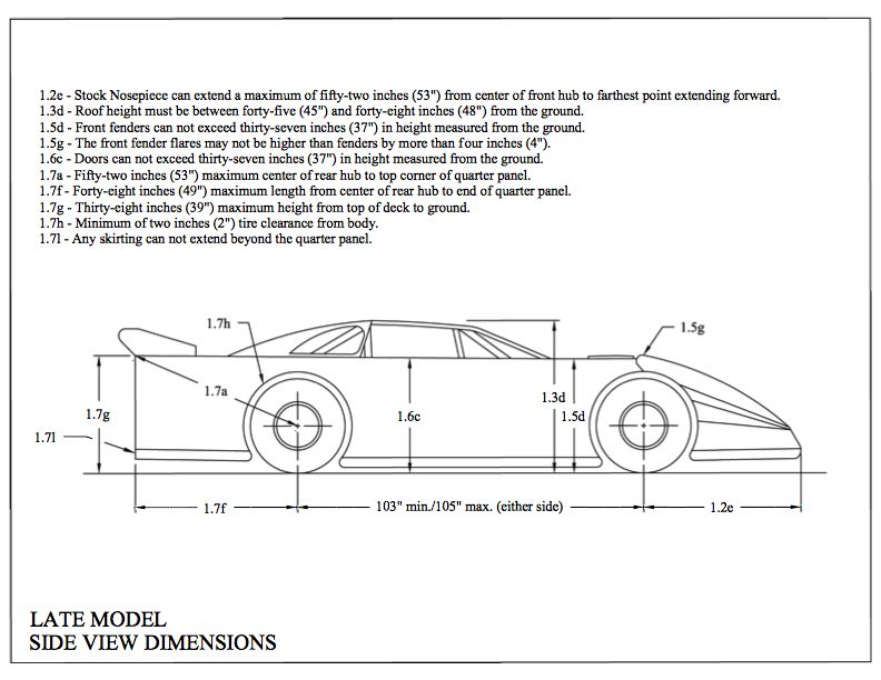
Section 16.0 – World of Outlaws Late Model Series & DIRTcar Late Model Rules
            ANY CAR, TEAM AND/OR DRIVER THAT DOES NOT MEET THESE SPECIFICATIONS AND/OR EQUIPMENT
            REQUIREMENTS WILL BE SUBJECT TO PENALTIES AS DETERMINED BY THE WORLD OF OUTLAW LATE MODEL
            SERIES OFFICIALS.

❖    The specifications published shall be considered a section of the “Official Rules and Specifications” for all events, series
     and sanctions by World Racing Group. All sections should be considered when determining specifications and
     governance.

    16.1 – Engines
       A.    Only conventional type V-8 engines with the cam in the block will be permitted. Cubic inch displacement is optional.
       B.    All engines must be based on a manufactured, factory design.
       C.    Aluminum or steel blocks will be permitted.
       D.    All engines must be normally aspirated with a single conventional-type four (4) barrel carburetor.
       E.    The engine must have an operating self-starting mechanism.
       F.    Only one distributor or magneto will be permitted. Cylinder designated individual coil systems will not be permitted.
       G. A maximum of 25 ½”-inches from the center of the ball joint to the front of the motor plate/engine bell housing flange will be
          permitted.
       H.    Only two (2) valves and one (1) spark plug will be permitted per cylinder.
       I.    In the event that there are new engine components and/or a new engine configuration they must be submitted per the World
             Racing Group submission requests prior to being introduced into competition.
     16.1.2 – Transmission/Driveline and Driveline Components
       A.    A functional clutch must be used. Direct drives systems of any-type will not be permitted.
       B.    The transmission must be bolted to the engine and it must have forward and working reverse gear(s) and must be able to shift
             to forward or reverse with engine running.
     16.1.3 – Driveshaft
       A.    The driveshaft must be a minimum of 2”-inches in diameter. All drive shafts must be painted white.
       B.    Only one (1) drive shaft connected from the transmission to the center section of the rear end will be permitted.
       C.    A minimum of one (1) driveshaft hoop / sling must be fastened securely to the frame. It is recommended that two (2)
             driveshaft hoops / slings be used.
     16.1.4 – Rear End
       A.    Any type of rear end differential / center section will be permitted.
       B.    Independent rear suspensions will not be permitted.
       C.    Full floating aluminum hubs with “wide 5” wheel bolt pattern must be used.
       D.    The axle housing must be of the “closed tube” design utilizing “full floating” magnetic steel axle tubes.
       E.    The center section of the axle housing must be manufactured of either aluminum or magnesium.
       F.    Axle tubes must be one (1) piece. Axle tubes must be manufactured of aluminum or magnetic mild steel. Axle tubes
             manufactured of exotic, heavy materials will not be permitted. The outside diameter of the axle tubes must not exceed three
             (3) inches. Axle tube internal inserts or external sleeves will not be permitted. The addition of any ballast weight to the axle
             housing will not be permitted.

    16.2 – Fuel, Fuel Cells and Fuel System
       A.    All cars must have fuel cells that meet and/or exceed FIA/FT3 or SFI 28.3 specifications. The fuel cell must have a maximum
             capacity of 35 gallons.
       B.    The fuel cell must be enclosed completely in a container that is a minimum thickness of 20-guage magnetic steel and/or
             .060”-inch aluminum.
       C.    Fuel cell cap must be a threaded cap and/or ATL Part # TF751 1/4 Turn Bullet Cap.
       D.    The entire container must be visible for ease of inspection.
E. The fuel cell must be mounted behind the rear axle between the rear tires, a minimum of 4”-inches ahead of the rear
bumper. The bottom of the fuel cell must not be any lower than the bottom of the rear end/quick change housing.
F. The fuel cell must be mounted with a minimum of two (2) .125”-inch thick steel straps. The straps must cover the entire cell.
Fuel cells that are mounted in a square tubing frame will be permitted. A minimum of 7/6”-inch ASTM Grade 8 bolts must be
used to mount the fuel cell to the frame.
G. The fuel pick-ups must be positioned on the top of the fuel cell and be constructed of steel. The fuel pick up must have a
check valve. Pick-ups on vertical sides prohibited.
H. Only racing gasoline or alcohol will be permitted for competition. Nitrous oxide, nitro-methane and/or propylene oxide will not
be permitted.
I. Competitors must be prepared to drain fuel from fuel cell for inspection.
J. Mechanical fuel pumps must be used. Fuel pumps must be engine mounted. Fuel pumps may be camshaft actuated or belt
driven. Electric pumps, primary and/or secondary, pressure systems, and additional reservoirs will not be permitted.
16.3 – Electrical Systems, Batteries, Electrical Accessories:
A. The battery must be securely mounted with positive fasteners and brackets. All battery supports and/or mounts must be
secure and braced in two (2) horizontal positions and one (1) vertical position.
B. The battery terminals must be insulated, and the battery enclosed with a non-conductive material that will prevent contact with
any part of the race car should the battery become dislodged from the battery mount.
C. One (1) mandatory battery disconnect switch must be installed on the rear deck, behind the driver seat, in a location that is
easily accessible from outside the race car. The switch must be clearly labeled with off/on direction. The switch must be
directly in-line with the NEGATIVE battery cable and be capable of completely disconnecting the NEGATIVE terminal of the
battery from the race car. Negative or “ground” wiring connections must not be made anywhere from the battery negative
terminal to the input side of the disconnect switch.
16.4 – Exhaust - Muffler and Sound Reduction Devices
A. The exhaust flow must be parallel to the ground. Exhaust systems that direct the flow toward the ground will not be permitted.
B. All exhaust systems/headers must end with a collector.
C. Several tracks have a locally enforced decibel rule, which preempt any particular muffler rule. Some tracks may have a
maximum sound level rule of 95 decibels at 100 feet. This rule will be enforced by local government agencies.
D. If a decibel rule is in place, then the decibel rule must be met, regardless of the specified muffler application.
16.5 – Traction Control / Radio / Transmission Devices
A. All electronic and/or computerized wheel spin and/or ignition retardation and/or acceleration limiting and/or traction control
devices of any type will not be permitted.
B. Adjustable ping control devices, dial a chip controls, timing controls and/or automated throttle controls will not be permitted.
C. Adjustable restrictor plates will not be permitted.
D. Remote control components of any-type will not be permitted.
E. Radios and/or devices for transmitting voice and/or data will not be permitted.
F. Data acquisition systems will not be permitted.
16.6 – Chassis/Frame
A. The minimum wheel base will be 103”-inches with a maximum wheel base of 105”-inches.
B. Frames fabricated using square tubing must be a minimum of 2”-inches x 2”-inches or approved rectangular magnetic steel
with a minimum material thickness of .083”-inches.
C. Frames fabricated using round tubing must be a minimum of 1.75” Outside Diameter magnetic steel tubing, 4130 Chrome
Moly or DOM with a minimum material thickness of .083”-inches.
D. Rear bumpers that are stubbed may only extend a maximum of 8”-inches beyond the frame. Any stubbed rear bumper that
extends further than the maximum of 8”-inches must be formed and directed 8”-inches toward the front of the car.
E. External rub rails will not be permitted.F. All cars must be equipped with a tow hook and/or strap for the purpose of towing.
G. All battery supports and/or mounts must be secure and braced in two (2) horizontal positions and one (1) vertical position.
H. Any frame built on or after January 1st, 2006, must have the builder’s unique serial number plate prominently attached to the
left side roll cage upright. The plate must be welded in place. All characters on the plate must be a minimum of ½”-inch in
height and the serial number must not exceed 8 characters.
16.7 – Roll Cage
A. All cars must have a roll cage fabricated from a minimum of 1-1/2” outside diameter with .065”-inch thick seamless magnetic
steel tubing.
B. The side roll bars and/or door bars must extend into the door panels.
C. A minimum of three (3) 1-1/2” outside diameter bars .065”-inch in thickness must be utilized on the left side of the
car in the door area.
D. Any of the bars that are utilized for the top portion of the roll cage, including, but not limited to the front and rear hoops, the
top hoop and the uprights, must extend a minimum of 1”-inch above the driver’s helmet.
E. All new frames and/or roll cages built on or after January 1st, 2006 an additional vertical side brace is required on the left side
in vertical alignment with the steering wheel.
16.7.1 – Driver side Intrusion plates
A. A minimum 1/8" (.125”) thick magnetic steel intrusion plate on the driver’s side door bars is mandatory.
B. Approved installations:
a. Welded plates- Individual plates between door bars are permitted but must be weld around the perimeter of each
opening. Minimum area covered is 16inches by 26 inches.
b. A minimum of 16” x 26” plate bolted to fabricated 1/8” (.125”) magnetic steel tabs, welded securely to the chassis, using a
minimum of eight (8) x 3/8” Allen button head bolts. A minimum of three (3) fabricated 1/8” (.125”) magnetic steel tabs
and 3/8” Allen button head bolts required across top of the intrusion plate, a minimum of three (3) fabricated 1/8” (.125”)
magnetic steel tabs and 3/8” Allen button head bolts required across the bottom of the plate, and one (1) fabricated 1/8”
(.125”) magnetic steel tabs and 3/8” Allen button head bolt in each in the middle front and middle rear of intrusion plate.
c. A minimum of 16” x 26” plate bolted to a minimum of six (6) approved-design door bar clamps using the included 12 x
1/2” Allen button head bolts per the manufacturer’s specification. A minimum of three (3) approved-design door bar
clamps and the included six (6) x 1/2” Allen button head bolts required across top of the intrusion plate and three (3)
approved-design door bar clamps and included six (6) x 1/2” Allen button head bolts required across bottom of intrusion
plate. Vendor and part number must be clearly labeled on part.
d. Current approved-design door bar clamps (as of December 1, 2018) – in order of submission:
i. Bicknell Racing Products – Part Number: BRP 954
ii. Wehrs Machine & Racing Products – Part Number: WM397
iii. Allstar Performance – Part Number: ALL4198
(no other manufacturer has submitted a design for approval at this time)
16.8 – Weight / Ballast (refer to 5.3 E-J for additional weight specifications)
A. The total weight of the car with the driver will be:
a. A minimum of 2,350 lbs. as weighed on the track scales for a car with an aluminum engine block.
b. For any car using the Chevrolet Performance 602 or 604, A minimum of 2,250 lbs. as weighed on the track scales.
c. At specified events a minimum of 2,300 lbs.as weighed on the track scales for a car with a Steel Block engine.
d. The overall weight for any car using a seat displaying a current valid SFT 39.2 seat certification may be reduced to 25
lbs. to compensate for the weight of the SFI 39.2 seat.
B. Additional added weight(s) up to 50 lbs. must be positively fastened by two 2½-inch, minimum grade 5 bolts with a minimum of
two (2) weight clamps. Threaded rods will not be permitted. All weights must be painted white and clearly labeled with the car
number on it.
C. Additional added weight(s) must be securely attached to the frame below the body decking.
D. Frame is defined as the steel welded structure only.
E. Any part that moves or is not a fixed component to the steel frame structure may not be used for any additional weight
attachments.
F. Additional added weight(s) attached to the rear bumper and/or outside the frame will not be permitted.
G. Any car that loses any weight/ballast during an event may be subject to a penalty.
H. Pellet-type and/or liquid-type weight/ballast will not be permitted.I. Driver operated weight adjustment, ‘weight jacking’ devices will not be permitted.
J. The scale(s) used for the event, provided by the series or the track will be considered the official scales for the event.
K. Scale(s) will be available for all teams to verify its car weight and determine the scale weight.
L. In the event of a car not meeting the required overall weight, Officials may allow a car to re-weigh up to (2) two additional times
by removing the car from the scale(s) and repeating the weighing procedure. If a car is allowed to re-weigh the overall weight
of the car recorded during the final weighing procedure will be the "official" weight of the car.
16.9 – Body (Refer to diagrams 1 - 4 attached)
16.9.1 – Overall Appearance
A. The car must be neat in appearance and must display the car number on the front nose and the rear fuel cell. The minimum
height for the number will be 6”-inches.
B. The car must have legible numbers on each side and on the roof a minimum of 18”-inches high,
16.9.2 – General Body
A. The nosepiece must match the body style of the make and manufacturer of the car and be the same as the make and
manufacturer of the motor (GM, Ford, Mopar).
B. All cars must have a minimum half-inch (1/2”) and a maximum of one (1) -inch radius at the top of fenders, doors and quarter
panels. Sharp edge(s) will not be permitted.
C. The floorboards and firewall must completely cover the driver’s area with no openings.
D. Fins and/or lips of any-type will not be permitted anywhere along the entire length of the car.
E. The bodyline must be a smooth even line from front to rear.
F. Wedge shape cars and/or body styles will not be permitted.
G. “Belly pans” or any type of enclosure on the bottom of the car will not be permitted. A skid plate to protect the oil pan is permitted.
A maximum 1/8” skid plate will be permitted.
H. Wings and/or tunnels and/or any type of air deflection device will not be permitted underneath the body and/or chassis of the
car.
I. A maximum of one (1) stone deflector, for rear mounted oil pumps, oil filters, and for the main oil tank will be permitted. The
deflector may be made of steel, aluminum, or heavy gauge wire. The cover may only be mounted near the unit it is designed to
protect with a maximum size of 18” x18” and only mounted from the upper right frame rail to the lower right frame rail.
J. Panels of any type under the rear deck running from the front to the rear of the car will not be permitted.
K. Bodies that are non-approved will be assessed a weight penalty. The minimum weight penalty will be as follows; 25 lbs.per
inch of the infraction.
L. Any style air cleaner scoop used must be positioned in front of/or around the air cleaner and must not exceed 1”-inch in height
above any part of the air cleaner. Any type of flange and/or air deflection device and/or fin that is designed to direct airflow will
not be permitted.
M. The top edge, measured from the ground, of the rear quarter, door and front fender to the point where the fender flare attaches
must be a straight line, within one inch on both sides of the car
16.9.3 – Nosepiece
A. Only approved nosepieces will be permitted. A list of approved manufactures and part numbers for competition in World of
Outlaw Late Model and DIRTcar UMP competition follows:
a. Dominator
b. MD3 – Performance Bodies
c. ARP Air Speed nose
d. Five-Star MD3 type
e. Performance Bodies/Five Star MD3 2015
f. Performance Bodies / Five Star 2016 Evolution
g. Performance Bodies / Five Star 2019 Evolution 2
B. Approved nose assemblies must be installed per the manufactures instructions. All nose assemblies must meet the
maximum/minimum dimensions, shall maintain manufacture appearance and not be altered.
C. Front nose assemblies, not meeting the maximum/minimum dimensions, at the series discretion, may be permitted to
compete as a “non-conforming” nose with a minimum of 50 additional pounds mounted in front of the motor plate. At series
discretion, degree on non-compliance may require additional weight and/or placement of penalty weight in front of radiator.
D. All nosepieces must be made of molded type material.
E. Nose filler panel shall be flat across to entire surface, dishing or raising prohibitedF. Two-piece noses must be positively fastened together in the center. Spacers added to gain width will not be permitted.
G. The nosepiece must be mounted in a manner that does not alter its original shape.
H. Alteration and/or additions may not be made to this area other than cooling holes as follows. A maximum of three two-inch
holes may be drilled into the nose for the sole purpose of air flow for engine cooling purposes. No ducts of any type will be
allowed.
I. The nosepiece can extend a maximum of fifty-three inches (53”) from the center of the front hub to the farthest point extending
forward.
J. The nosepiece must display a headlight decal package. A one-race grace period, running contrasting color tape in the shape
of a headlight will be permitted.
K. Right Side Nose Height Rule – The maximum height from the ground to the top of the nose splitter shall be 15 inches.
L. Front nose must be mounted in the center of the car.
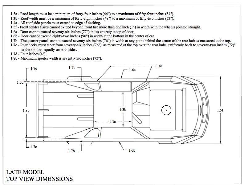
16.9.4 – Roof
A. The roof length from front-to-back must be a minimum of 44”-inches with a maximum of 54” inches.
B. The roof width from side-to-side must be a minimum of 48”-inches to a maximum of 52”-inches.
C. The roof must be stock appearing and be mounted level to the body.
D. The minimum height of the roof will be 45”-inches with a maximum height of 48”-inches.
E. The roof must be mounted parallel to the body and near the center of the car as viewed from the front of the car.
F. A maximum 1-1/2” roll, turned downward will be permitted along the front edge of the roof. A maximum 1”-inch roll, turned
downward, will be permitted along the rear edge of the roof. These modifications will be permitted to improve the strength of
the roof. Any other modifications to the roof will not be permitted.
G. Flat and/or odd shaped roofs will not be permitted. Bellied and hollowed roofs will not be permitted.
H. Sun/antiglare shields may not be used.
I. A maximum of two (2) roof edge bead rolls of a maximum height of ½”-inch the length of the roof will be permitted.
J. The roof posts and spoiler support(s) must not overlap.
K. The maximum thickness of the roof at any point will be ½”-inch.
L. The roll cage and associated frame members above the interior panels (decking) must remain open. Enclosures will not be
permitted.
16.9.5 – Roof Supports and Window Side Panels
A. All roof side panels must extend to the edge of the body.
B. The roof side panel window size must be a minimum of 10”-inches x 15”-inches and must match drawing number -2- side view.
A maximum crown of two (2) inches will be permitted, measured from the center of a common tangent point on either side of
the crown.
C. The left and right-side window panels must match.
D. A maximum bow of two (2”)-inches outward on the window side panels as viewed from behind will be permitted.
E. The front roof supports must extend forward to the rear of the hood. The front roof supports may be a maximum of
4”-inches wide. The left and right front roof supports must match.
16.9.6 – Front Fenders, Fender Flares and Hood
A. The hood must be level and flat from the left to the right side of the car.
B. The front fenders can be a maximum of 2 inches from left to right.
C. The outside edges of the hood and/or the fender must remain inside the overall bodyline.
D. The front fender may be a maximum of 37”-inches in height, measured vertically from the ground to the top of the fender behind
the front tires and at the right front fender and door “T-bar” location.
E. The front fender flares must be made of plastic and must not alter the original shape of the nose piece.
F. The front fender flares must not extend beyond the front tires more than 1”-inch per side to a maximum width, edge-to-edge, of
90”-inches in width with the wheels pointed straight.
G. The front fender flares must be flat across the entire width of the car. Front fender flairs must not extend, bubble or rise more
than four inches (4”) at any point of the front fenders and/or hood.
H. The front fender flares must have collapsible supports.I. All cars must have FULL FENDER TOPS.
16.9.7 – Doors
A. The door-to-door measurement must not exceed 76”-inches in width at the top of the doors.
B. The door-to-door measurement must not exceed 90”-inches in width when measured at the bottom of the doors in the
center of the car.
C. The doors must not exceed 37”-inches in height when measured from the ground to the top of the door. The measurement
from the rear of the top deck to the highest point of the right front fender must be a straight line that must be within 1
inch when a straight edge or string is installed on the racecar the entire surface of the body must be within 1 inch of
the plane
D. The door sides may not break inward from the top 76”-inches and bottom 90”-inch measurements. Hollow and/or belled doors
will not be permitted.
E. The minimum ground clearance will be 3”-inches.
16.9.8 – Quarter Panels
A. The maximum distance from the center of the rear hub to the top quarter of the panel is 53”-inches.
B. The quarter panels must not exceed 76”-inches in width at any point as measured at the top of the panels.
C. The rear deck must taper in a symmetrical manner from the center of the rear hub to the rear spoiler with a minimum width of
72”-inches and a maximum width of 76”-inches.
D. The maximum width for the quarter panels measured from outside-to-outside measured 19”-inches from the ground and/or at
the bottom of the quarter panel will be 82”-inches.
E. Any breaks and/or bends formed in the sides of the quarter panel that move the panel toward the center of the car will not be
permitted. Hollow and/or bellied panels will not be permitted.
F. The maximum distance from the center of the rear hub to the rear trailing edge of the quarter panel will be 49”-inches.
G. A minimum of 2”-inches of tire clearance between the tire and the body will be required.
H. Skirting that extends behind the rear quarter panel will not be permitted.
I. Left rear quarter panels must extend downward from the deck a minimum of 33”-inches and maximum of 36”-inches
including plastic when measured at the front and rear of quarter panel. Right rear quarter panel must extend downward
from the deck 27”-inches without plastic or 31”-inches with plastic when measured front to rear.
J. Deck height will be measured at the nose piece splitter at a max height of 15”-inches from the ground to the top. Deck
height will be measured at 39”-inches from top of rear deck to the ground.
16.9.9 – Spoilers and Spoiler Braces/Supports
A. Only aluminum and/or Lexan and/or Lexan-type rear spoilers will be permitted.
B. The maximum overall height of the rear spoiler will be 8”-inches. The maximum width of the rear spoiler, including braces and/or
supports is 72”-inches.
C. The rear spoiler must begin at the deck and extend 8”-inches from that point. Suspending the spoiler to create a wing-type
device will not be permitted.
D. The rear spoiler must begin at the rear most point of the quarter panels.
E. Only three spoiler braces/supports will be permitted. The front edge of the spoiler brace/support must be in line with the spoiler.
F. The outside spoiler supports must not be mounted any wider than the top of the quarter panel(s) and must be centered on the
rear deck.
G. In the event that aluminum angle is used to brace the upper edge of the spoiler, the angle must not add to the height and/or
length of the spoiler in any way.
16.9.10 – Interior
A. The interior of the cockpit must be a minimum of 11”-inches below the top of the roof and/or roll cage, measured perpendicular
to the ground from the bottom of the roof to the cockpit deck. Roof rolls are not part of the measurement.
B. The side window opening(s) must be 15”-inches from the top of the door to the bottom of the roof.
C. Support bars that block the right window from the driver exiting the cockpit will not be permitted.
D. A rock guard (Lexan screen) can be no higher than 4 inches and no farther back than the front edge of the right-side
head rest.
E. If the interior deck drops, the drop must begin at the rear of the engine plate with a maximum of 4 inches and must not drop
below 4 inches at the rear of the hood. The start of the dropped interior must remain closed as a part of the fire wall. The entirewidth must be closed off with sheet metal.
F. The interior must gradually taper up to the quarter panel height and must be level for a minimum of 20 inches from the rear of
the quarter panel and deck.
16.9.11 – Driver Compartment
A. A full metal firewall fabricated from magnetic steel and/or aluminum must encompass the driver’s compartment from front-to-
rear, on both sides and floor boards.
B. All cars must be equipped with a quick-release type steering wheel that is a full circle.
C. Mirrors of any-type will not be permitted.
D. Radios and/or electronic and/or data communication devices will not be permitted.
E. Any edge and/or sheet metal end in and around the driver compartment must be protected with trim and/or beading and
rounded. Sharp and protruding edges will not be permitted.
F. A substantial rock guard with a minimum of three (3) additional roll bars must be mounted in front of the driver. The rock guard
must be made from wire screen. Windshield screens must be a minimum of .090-inches and must be securely fastened.
G. Cockpit adjustable components with the exception of brake bias adjusters will not be permitted. Adjusters of any-type, including
but not limited to adjustable shocks, hydraulic or pneumatic weight jacks, trackers, ignition boxes or similar adjustable
components will not be permitted inside the cockpit of the car or within reach of the seated driver.
16.10 – Brakes, Brake Components, Wheel Hub:
A. Brake calipers must be manufactured of aluminum.
B. The brake caliper including brake caliper pistons must be used as produced by the brake caliper manufacturer.
C. Brake rotors must be manufactured of magnetic or stainless steel.
D. Brake rotors must be used as produced by the brake rotor manufacturer.
E. Wheel hubs must be manufactured of aluminum or magnesium.
F. Wheel hubs must be used as produced by the wheel hub manufacturer.
G. The combined weight of the wheel hub, wheel bearings and seal, spindle nut and washers, brake rotor and attaching
hardware, the axle cap, and the wheel spacer must not exceed 27 pounds.
16.11 – Rear Suspension & Suspension Components
A. General
a. Rear suspension designs and applications are constantly evolving. Although the intent of the rear suspension rules are
an attempt to accommodate the majority of suspension and suspension component designs and applications currently
being used in competition, the rules cannot be absolute. Any and all new designs or modifications to an existing
suspension and/or suspension component must be communicated to and approved by the Series Director before being
used in competition.
b. Rear suspension must utilize either coil or leaf springs.
c. Rear suspension configuration used on current and new chassis(s) must be the design commonly known as four (4) link.
Older cars currently competing with other rear suspension designs will be allowed to compete until further notification at
the discretion of the Series Director.
d. In regard to swing arm and/or Z-Link suspension, these suspension types are permitted. The shock on a swing arm or z-
link rear suspension may mount to the bird cage or bottom radius rod. Top and bottom solid links must be mounted on
hiems and run in the opposite direction of bird cage.
e. Bump sticks are not allowed anywhere on the car.
B. Axle Housing, Rear Differential
a. The axle housing must be of the “closed tube” design utilizing “full floating” magnetic steel axle shafts.
b. The center section of the axle housing must be manufactured of either aluminum or magnesium.
c. Axle tubes must be one (1) piece. Axle tubes must be manufactured of aluminum or magnetic mild steel. Axle tubes
manufactured of exotic, heavy materials will not be permitted. The outside diameter of the axle tubes must not exceed
three (3) inches. Axle tube internal inserts or external sleeves will not be permitted. The addition of any ballast weight to
the axle housing will not be permitted.
d. Axle tube, including axle tube sleeves, donuts, or added parts may not exceed (3) three inches O.D. (outside diameter) at
any point from center section to hub.C. Rear Suspension Frame Mounts
a. The frame/roll cage structure must have integral welded mounting brackets for the attachment of rear suspension
components. Frame suspension mounts may be welded or bolted securely (without any movement) to the frame/roll cage
structure.
b. The only materials used to fabricate frame suspension mounts that will be permitted are magnetic steel or aluminum.
c. Frame suspension mounts may be either a single or double shear configuration for mounting suspension components.
d. Single shear frame suspension mounts must be a minimum of 1/4 inch in thickness. Double shear frame suspension
mounts must be a minimum of 3/16-inch thickness on both sides of the mount.
e. All frame suspension mount component mounting holes must be round and sized correctly for the fastener being used.
Clearance between the fastener and the mounting hole must not exceed the next fractional drill size. Example: 1/2-inch
fastener, 33/64-inch mounting hole.
D. Axle Housing Mounts
a. Only one (1) axle-housing mount per side will be permitted.
b. The only materials used to fabricate axle housing mounts (birdcages) that will be permitted is aluminum or magnetic mild
steel. Axle housing mounts fabricated of exotic, heavy materials will not be permitted.
c. When fabricating axle housing mounts detail must be paid to functionality. The completed axle housing mounts, when
comparing the right and the left side, must be as similar in design as possible.
d. Axle housing mounts may be a solid (welded) type or a floating type (birdcage) design.
e. The final assembled axle-housing mount must be a one (1)-piece mount. When a floating type mount (birdcage) is
fabricated using two (2) pieces, the two (2) pieces must create a common one (1)-piece pivot (barrel). The two (2) pieces
must be fastened or welded together to prevent independent movement of the two (2) pieces. The axle-housing mount
must attach directly to the axle tube with clearance only to permit rotation of the entire mount. Fore, aft or vertical
movement of the mount or the axle housing within the mount will not be permitted.
f. Mounts for suspension attaching (radius) rods must be an integral part of the axle-housing mount. The mounts may be
either a single or double shear configuration. When using a single shear configuration, a minimum thickness of 1/4 inch
for magnetic steel or 1/2 inch for aluminum is required. When using a double shear configuration, a minimum thickness
of 3/16 inch for magnetic steel or 1/4 inch for aluminum is required. Dynamic movement of any mount other than a
rotational and pivoting movement as a result of suspension travel will not be permitted.
g. Unless otherwise authorized by the Series Director, the mounting of any component(s) other than suspension attaching
(radius) rods or shocks will not be permitted on the axle housing mounts.
E. Rear Suspension Attaching (Radius) Rods
a. A maximum of two (2) attaching (radius) rods per side will be permitted.
b. The only materials used to fabricate attaching (radius) rods that will be permitted are magnetic steel or aluminum
c. Attaching (radius) rods may be solid or tubular material. The material may be round or hexagon in shape.
d. Spherical rod ends, or steel clevises must be used at the end of each rod for pivoting, static length adjustment, and
mounting. Bushings of any type will not be permitted.
e. The final assembled attaching (radius) rod must not have the capability to change length dynamically by any means or
devices.
f. Spherical rod end sizes may be a minimum of a 5/8-inch rod end body with a 1/2-inch bearing to a maximum of a 3/4-
inch rod end body with a 3/4-inch bearing.
g. In all applications, the correct size fastener must be used when mounting the spherical rod end to a bracket (example:
1/2-inch fastener must be used with a 1/2-inch bearing and mounting hole). Metal step spacers will be permitted to
reduce the hole size of the spherical rod end bearing.
h. Attaching (radius) rods must mount directly to the frame suspension mount at the forward end and to the axle-housing
mount at the rearward end.
i. All rear suspension fasteners must be magnetic steel with a minimum diameter of 1/2 inch. The use of grade 8 fasteners
is highly recommended. All fasteners must be correctly sized for the component and application of use.
j. When rear suspension assembly is completed, the attaching (radius) rods must have a minimum of eight (8) inches
between the pivots at both the frame suspension mount and the rear axle-housing mount.
F. Rear Droop Limiter
a. One (1) droop-limited chain per side will be permitted.
b. The droop limiting chain may incorporate bump stops and/or springs.c. The droop limiting chain must attach to a collar or bearing type mount on the rear axle tube and to the frame assembly
directly above the lower mount. Chains to the rear axle mount (birdcage) will not be permitted.
d. Droop limiting chains must be mounted so that when taunt they are as close to vertical as possible.
G. Torque Control Devices
a. Lift arm assemblies and pull bars will be permitted.
b. Only one (1) torque control device may be used.
c. Lift arms must attach to the axle housing using a mounting configuration that prevents any movement between the lift
arm and the rear axle housing. A gusset or brace bar to prohibit side-to-side flex will be permitted.
d. The forward end of the lift arm may use a spring over shock assembly (5 th coil), a spring or bushing, and a limiting chain.
e. Pull bars may be adjustable on both ends; however, the adjustments must remain fixed during competition. Adjustors
within reach of the driver will not be permitted.
H. Rear Springs
a. Coil springs or leaf springs will be permitted.
b. Coil springs must be manufactured from magnetic steel. Leaf springs must be manufactured from either magnetic steel
or approved composite material.
c. Spring preload adjustments for coil springs must be made using mechanical adjusting nuts on the shock body.
d. Spring preload adjustments for leaf springs must be made using a mechanical adjusting device such as an adjustable
shackle or threaded rod type mount.
e. Other than spring dampening by the shock absorber, hydraulic, pneumatic, or electrically controlled adjusting devices,
(static or dynamic) that affect spring preload or race car heights will not be permitted.
16.11.1 – Shock Absorbers
A. Shocks are intended to dampen and help control spring frequencies in both the compression and rebound motions. The
amount of force applied to move the shock piston and shaft assembly may be varied with the option of shock “builds” however
the piston and shaft assembly must have the ability to move in both directions.
B. Mono-tube, single piston, nitrogen gas charged shocks will be permitted. All shocks must utilize mechanical oil controls, such
as: spring shim(s), drum and disc(s), check ball and spring, needle and seat for internal and external shock adjustments.
Magnetic and/or electro-magnetic controls are not permitted. Remote nitrogen gas reservoirs will be permitted. The remote
reservoirs may contain a compression adjustor. Adjustments described above are the only shock adjustments that will be
permitted.
C. Shock adjustments while the vehicle is in motion will not be permitted.
D. Shocks and shock components may only be manufactured from steel or aluminum.
E. Rotating parts will not be permitted inside or mounted to the shock absorber. Inertia/gyro style shocks are not permitted.
F. Thru-rod shocks will not be permitted.
G. Unless otherwise authorized, all shocks must be mounted as close to vertical as possible.
H. Approved shock locations are as follows:
I. One (1) shock will be permitted at each front wheel
J. One (1) shock will be permitted at the right rear wheel
K. Two (2) shocks will be permitted at the left rear wheel. When using only one (1) shock at the left rear wheel, the shock must
be mounted behind the rear axle tube. When two (2) shocks are used at the left rear wheel, one (1) shock must be mounted
behind the rear axle tube and the second shock must be mounted on top of or forward of the rear axle tube.
L. One (1) shock will be permitted mid-ship at the front of the lift arm assembly.
M. One (1) braking shock will be permitted. The shock must be mounted within three (3) inches of the center line of the rear axle
center section. This shock must be mounted horizontally.
N. Prior to introduction into competition a new design shock absorber must be submitted to World Racing Group / World of
Outlaws Craftsman Officials for approval. Shock absorber manufacturers may be required to provide a board of components
for inspection and display.
O. Air shocks are permitted.16.11.2 – Steering Components
A. Only one power steering pump allowed. Electronic steering or electronic steering components will not be permitted.
16.12 – Wheels
A. Only aluminum wheels will be permitted for competition.
B. The wheels must be mounted to the hubs utilizing lug nuts. “Knock off” and/or single type wheel mounting systems will not be
permitted.
C. The maximum wheel width that will be permitted is 14”-inches.
D. The combined weight of the wheel, wheel hardware, wheel disc and fasteners, and tire must not exceed 40 pounds*. *The
maximum combined weight in this rule is based upon current tire rules and may need to be adjusted in the event of an
alternate tire.
E. The maximum front track width will be 90”-inches and the maximum rear track width will be 88”-inches, measured from the
outside edge of the tire to the outside edge of the tire.
F. Only approved wheel discs will be permitted. Approved wheel discs are wheel discs that are fastened to the wheel using a
minimum of three (3), 1/4 or 5/16-inch diameter magnetic steel hex head bolts. The use of wheel discs with any other type of
fastener will not be permitted.
G. Only aluminum wheel spacers will be permitted.
H. Wheel/Air Bleeders are not allowed anywhere on the car.
16.13 – Tires
16.13.1 – World of Outlaws Late Model Series Tire Rules
A. For the 2019 World of Outlaws Late Model Series racing season, an open tire rule is in effect, provided, the tires meet the 2019
World of Outlaws Late Model Series Tire Specifications.
B. The maximum size for any tire in competition is 11”-inches x 29”-inches x 15”-inches, unless otherwise specified and made
known to all competitors.
C. The maximum outside circumference of the tire will be 93”-inches, unless otherwise specified and made known to all
competitors.
D. The maximum width of the tires measured from the outside edge(s) of the sidewalls across the face of the tire will be 16 ¾”-
inches. There will be a tire hoop used for inspection and the tire must pass through the tire hoop freely, without any manipulation
or outside contact.
E. The tire rule for any event may be amended from time to time and will be made known to all competitors.
F. Tires changes will not be permitted once a car has been presented to the starting grid/lineup area for the feature race. Any
cars making a tire change will forfeit their assigned starting position for that particular race and start from the rear of the field.
G. Chemical alterations, vulcanizing, tire softening, defacing and/or altering the face of the tire lettering and/or tire stamping will
not be permitted. Chemicals or tire softening is not permitted at any time. Tires may be inspected at any time. Any violation
with any tire presented for competition may result in immediate disqualification from the events and/or other penalties including
but not limited to; loss of money, fine, loss of points and/or suspension.
16.13.2 – DIRTcar Weekly Racing & Special Event Tire Rules
A. Only the Hoosier LM20, LM30S and LM40 tires will be permitted for competition. The weekly sanctioned track has the option of
all 20s; all 30s; or all 40s. There is a right rear option of 20/30/40 (track may limit option to one, two or all three). Siping and
grooving is allowed. Events at Eldora Speedway and others as announced prohibit grooving and siping on any tire. Refer to
specific event bulletin for details.
B. Only approved tires will be permitted for use in competition.
C. The maximum size for any tire in competition is 11”-inches x 29”-inches x 15”-inches, unless otherwise specified and made
known to all competitors.
D. The maximum outside circumference of the tire will be 93”-inches, unless otherwise specified and made known to all
competitors.
E. The maximum width of the tires measured from the outside edge(s) of the sidewalls across the face of the tire will be 16 ¾”-
inches. There will be a tire hoop used for inspection and the tire must pass through the tire hoop freely, without any manipulation
or outside contact.
F. The tire rule for any event may be amended from time to time and will be made known to all competitors.G. Tires changes will not be permitted once a car has been presented to the starting grid/lineup area for any race. Any cars making
a tire change will forfeit their assigned starting position for that particular race and start from the rear of the field.
H. Chemical alterations, vulcanizing, tire softening, defacing and/or altering the face of the tire lettering and/or tire stamping will
not be permitted. Chemicals or tire softening is not permitted at any time. Tires may be inspected at any time. Any violation
with any tire presented for competition may result in immediate disqualification from the events and/or other penalties including
but not limited to; loss of money, fine, loss of points and/or suspension.
16.14 – Personal Safety Equipment – see section 3.0
16.15 – Other
A. Cars will not be permitted to make a qualifying attempt without passing technical inspection. All cars must be
available for inspection prior to the time of the driver’s meeting. Following the driver’s meeting, covers of any-type
on the racecar will not be permitted.
B. All cars may be subject to technical inspection at any time.
C. Full or partial car covers will be permitted only when there is inclement weather.
D. It is recommended that all teams have a fire extinguisher in the rear of their transporter. The fire extinguisher is recommended
to be a minimum 0f 2.5 gallons FFF type chemical and/or equivalent.
E. All drivers are required to have a one-way radio. The one-way radio must be working and active prior to any ‘on-track’ activity.
Two-way radios, crew-member to driver and/or any other means of electronic communication, other than the one-way radio,
will not be permitted.
F. Seven (7) days prior to any scheduled and/or sanctioned one (1) day World of Outlaws Late Model Series Series event
paying less than $20,000-to-win race teams will not be permitted to rent, test and or attend any practice session(s) at the
scheduled track. Any race team and/or driver in violation will be given one (1) lap of qualifying and the best the qualifying
position that will be earned is 50% + 1 of the entered cars for that event.
G. No cameras and/or video recorders and/or photographic recording equipment may mounted below the deck.
16.16 – Series Decal and Patches
A. All participants will be required to display decals as provided on the decal verification sheet prior to entering into competition. If
any required decal is not displayed loss of any awarded money will be the penalty.
B. The World of Outlaws Late Model Series decal is required on both sides of the car for all cars participating in the event. The
decal shall be visible from both sides of the car. Preferred location is at the base of the front a-post on the door panel.
Alternative location or a secondary location is the outer spoiler vertical blade.
C. The World of Outlaws Late Model Series logo must be placed as high as possible on either the right or left front of the upper
chest area of the driver’s uniform. The World of Outlaws Craftsman brand logo must be placed as high as possible on both
sleeves of the driver’s uniform. Driver must display the series patch on their uniform to receive point fund awards.
D. Contingency and sponsorship awards, any team participating must meet the requirements of the award(s) such as decals,
patches, product use and verification. There will be a written deadline presented to the teams prior to the start of each season
for each element to be in place for the award requirements. If it is an existing program it will roll over from the prior season
and the program will begin at the first race of the season.
E. The World of Outlaws Late Model Series Officials may refuse to allow a participant to compete in an event if it is determined
at their discretion that any advertising and/or sponsorship or similar agreement is detrimental to the sport, the World of
Outlaws Late Model Series, the event promoter, the World Racing Group for any reason, including the image of the sport.
F. Unless instructed to do otherwise the top three (3) finishers from the Feature, after being weighted, must proceed directly to
victory lane and participate in all victory lane activities, including, but not limited to, top 3 photos, media interviews, victory
lane photos, etc. Failure to comply will result in a minimum $500 fine. Any extenuating circumstances will be considered.
G. Team Transports and/or Souvenir Transport/Trailers if commercial vehicles, will be required to display the World of Outlaws
Late Model Series logos in three locations (driver side, passenger side and tailgate). The display size will be as follows; 24”-
wide x 27”-tall – Team Transports 18”-wide x 24”-wide Souvenir Trailers.
H. Failure to comply with any of the above rules may result in a loss of Point Fund monies, purse monies and/or any other
penalty as deemed necessary by World Racing Group and/or World of Outlaws Late Model Series Officials.16.17 – Drawings
1.7d
You can also read