4th Slide Set Operating Systems - Prof. Dr. Christian Baun
←
→
Page content transcription
If your browser does not render page correctly, please read the page content below
Hard Disk Drives (HDD)                               Solid State Drives (SSD)                              RAID

                                            4th Slide Set
                                          Operating Systems

                                          Prof. Dr. Christian Baun

                                  Frankfurt University of Applied Sciences
                              (1971–2014: Fachhochschule Frankfurt am Main)
                                Faculty of Computer Science and Engineering
                                      christianbaun@fb2.fra-uas.de

Prof. Dr. Christian Baun – 4th Slide Set Operating Systems – Frankfurt University of Applied Sciences – WS2021    1/32
Hard Disk Drives (HDD)                               Solid State Drives (SSD)                              RAID

Learning Objectives of this Slide Set

       At the end of this slide set You know/understand. . .
               the structure, functioning and characteristics of Hard Disk Drives
               the structure, functioning and characteristics of Solid State Drives
               the functioning and the most commonly implemented variants of
               Redundant Array of Independent Disks (RAID)

Exercise sheet 4 repeats the contents of this slide set which are relevant for these learning
objectives

Prof. Dr. Christian Baun – 4th Slide Set Operating Systems – Frankfurt University of Applied Sciences – WS2021    2/32
Hard Disk Drives (HDD)                               Solid State Drives (SSD)                              RAID

Hard Disk Drives

       HDDs are approx. 100 times less expensive per bit versus main memory
       and they offer approx. 100 times more capacity
               Drawback: Accessing data on HDDs is approx. 1000 times slower
       Reason for the poorer access time:
               HDDs are mechanical devices
                       They contain one or more discs, rotating with 4200, 5400, 7200, 10800,
                       or 15000 revolutions per minute (RPM)
       For each side of each disk, an arm exists with a read-and-write head
               The read-and-write head is used to detect and modify the magnetization
               of the material
               The distance between disk and head is approx. 20 nanometers
       Also, HDDs have a cache (usually ≤ 32 MB)
               This cache buffers read and write operations

Prof. Dr. Christian Baun – 4th Slide Set Operating Systems – Frankfurt University of Applied Sciences – WS2021    3/32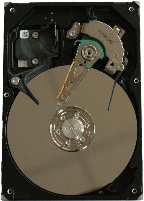
Hard Disk Drives (HDD)                                 Solid State Drives (SSD)                           RAID

 Logical Structure of Hard Disk Drives (1/2)
       The surfaces of the platters (discs)
       are magnetized in circular tracks by
       the heads
       All tracks on all disks at a specific
       arm position are part of a cylinder
       The tracks are divided into logical
       units (segments of a circle), which
       are called blocks or sectors
               Typically, a sector contains
               512 bytes payload
               Sectors are the smallest addressable
               units of HDDs
Image source (structure): Henry Mühlpfordt. Wikimedia
(CC-BY-SA-1.0)
Image source (HDD): purepng.com (CC0)

Prof. Dr. Christian Baun – 4th Slide Set Operating Systems – Frankfurt University of Applied Sciences – WS2021    4/32
Hard Disk Drives (HDD)                               Solid State Drives (SSD)                             RAID

 Logical Structure of Hard Disk Drives (2/2)
       If data need be modified, the entire
       sector must be read and rewritten
       Today, clusters are addressed by the
       software (see slide set 6)
               Clusters are groups of sectors with
               a fixed size, e.g. 4 or 8 kB
               In file systems of modern operating
               systems, clusters are the smallest
               addressable unit of HDDs

Image source (structure): Henry Mühlpfordt. Wikimedia
(CC-BY-SA-1.0)
Image source (platter): Tim Bielawa. The Linux Sysadmins Guide to
Virtual Disks (CC-BY-SA-4.0)

Prof. Dr. Christian Baun – 4th Slide Set Operating Systems – Frankfurt University of Applied Sciences – WS2021    5/32
Hard Disk Drives (HDD)                               Solid State Drives (SSD)                              RAID

Addressing Data on Hard Disk Drives
       HDDs with a capacity ≤ 8 GB use the Cylinder-Head-Sector addressing
       CHS faces several limitations:
               The Parallel ATA interface and the BIOS offer just. . .
                       16 bits for the cylinders (up to 65,536)
                       8 bits for the heads (up to 255. Head number 0 is not used)
                       8 bits for the sectors/track (up to 255. Sector number 0 is not used)
       ≤ 7.844 GB can be addressed this way

       1024 cylinders * 255 heads * 63 sectors/track * 512 bytes/sector = 8,422,686,720 bytes
       8,422,686,720 bytes / 1024 / 1024 / 1024 = 7.844 GB

       No 2.5” or 3.5” HDD contains > 16 heads!!!
               Logical heads were used
       HDDs with a capacity > 7.844 GB use Logical Block Addressing
       (LBA)
               All sectors are numbered consecutively beginning with 0
Prof. Dr. Christian Baun – 4th Slide Set Operating Systems – Frankfurt University of Applied Sciences – WS2021    6/32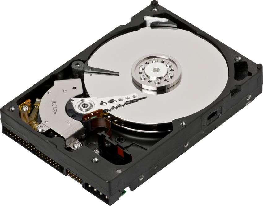
Hard Disk Drives (HDD)                               Solid State Drives (SSD)                                 RAID

Logical Block Addressing (LBA)

                                                                                               Image source

                                                                                               IT-Handbuch für
                                                                                               Fachinformatiker.
                                                                                               Sascha Kersken.
                                                                                               6th edition.
                                                                                               Rheinwerk Verlag

       When CHS addressing is used, all tracks contain the same number of
       sectors
               Each sector stores stores 512 bytes of payload
       Drawback: Storage capacity is wasted, because the data density
       decreases from the inner tracks to the outer tracks
       When LBA is implemented, this drawback does not exist
Prof. Dr. Christian Baun – 4th Slide Set Operating Systems – Frankfurt University of Applied Sciences – WS2021       7/32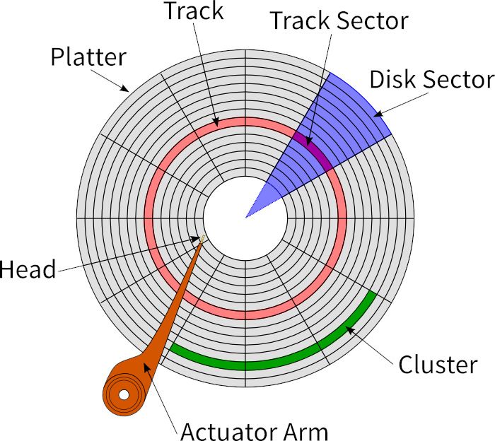
Hard Disk Drives (HDD)                                 Solid State Drives (SSD)                                RAID

 Required Time to access Data on HDDs
        The access time is an important performance factor
        2 factors influence the access time of HDDs
            1   Average Seek Time
                        The time that it takes for the arm to reach a desired track
                        Is for modern HDDs between 5 and 15 ms
            2   Average Rotational Latency Time
                        Delay of the rotational speed, until the required disk sector is located
                        under the head
                        Depends entirely on the rotational speed of the disks
                        Is for modern HDDs between 2 and 7.1 ms

                                                                 [ms]       [sec]                 [ms]
                                                        1000           × 60       × 0.5   30,000
                                                                 [sec]      [min]                [min]
 Average Rot. Lat. Time [ms] =                                                          =
                                                                    revolutions            revolutions
                                                                       [min]                  [min]
Why does the equation contain 0.5 ?

Once the head has reached the right track, on average a half rotation of the disk must be waited for the correct sector to be under
the head =⇒ Average Rotational Latency Time = half Rotational Latency Time

Prof. Dr. Christian Baun – 4th Slide Set Operating Systems – Frankfurt University of Applied Sciences – WS2021                 8/32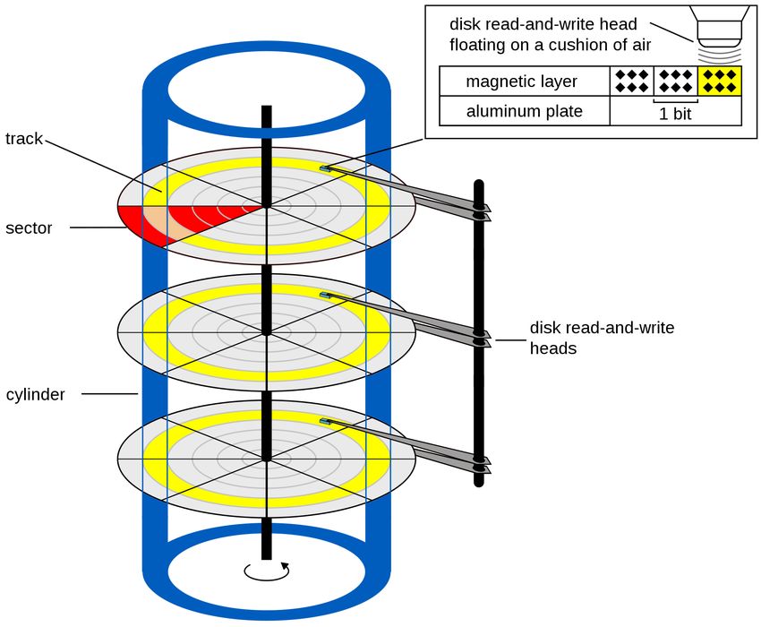
Hard Disk Drives (HDD)                               Solid State Drives (SSD)                              RAID

Solid State Drives (SSD)
       Are sometimes falsely called Solid State Disks

      Do not contain moving parts
      Benefits:
              Fast access time
              Low power consumption
              No noise generation
              Mechanical robustness
              Low weight
              The location of data does not
              matter =⇒ defragmenting
                                                                Image (SSD): Thomas             Image (HDD): Erwan Velu.
              makes no sense                                    Springer. Wikimedia (CC0)       Wikimedia (CC-BY-SA-1.0)

       Drawbacks:
               Higher price compared with HDDs of the same capacity
               Secure delete or overwrite is hard to implement
               Limited number of program/erase cycles
Prof. Dr. Christian Baun – 4th Slide Set Operating Systems – Frankfurt University of Applied Sciences – WS2021        9/32
Hard Disk Drives (HDD) Solid State Drives (SSD) RAID
Functioning of Flash Memory
Data is stored as electrical
charges
In contrast to main memory, no
electricity is required to keep the
data
Each flash memory cell is a transistor and has 3 connectors
Gate = control electrode
Drain = electrode
Source = electrode
The floating gate stores electrons (data)
Completely surrounded by an insulator
Electrical charge remains stable for years
Well written explanation about the functioning of flash memory
Benjamin Benz. Die Technik der Flash-Speicherkarten. c’t 23/2006
Prof. Dr. Christian Baun – 4th Slide Set Operating Systems – Frankfurt University of Applied Sciences – WS2021 10/32Hard Disk Drives (HDD) Solid State Drives (SSD) RAID
Reading Data from Flash Memory Cells
A positively doped (p)
semiconductor separates the 2
negatively doped (n) electrodes
drain and source
Equal to a npn transistor, the
npn passage is not conductive
without a base current
Above a certain positive voltage (5V) at the gate (threshold) a n-type
channel is created in the p-area
Current can flow between source and drain through this channel
If the floating gate contains electrons, the threshold is different
A higher positive voltage at the gate is required, so that current can flow
between source and drain
This way the stored value of the flash memory cell is read out
Prof. Dr. Christian Baun – 4th Slide Set Operating Systems – Frankfurt University of Applied Sciences – WS2021 11/32Hard Disk Drives (HDD) Solid State Drives (SSD) RAID
Writing Data into Flash Memory Cells
Data is stored inside flash
memory cells by using
Fowler-Nordheim tunneling
A positive voltage (5V) is applied to the control gate
As a result, electrons can flow between source and drain
If the high positive voltage is sufficient high (6 to 20V), some electrons
are tunneled (=⇒ Fowler-Nordheim tunneling) through the insulator
into the floating gate
This method is also called Channel Hot Electron Injection
Recommended Source
Flash memory. Alex Paikin. 2004. http://www.hitequest.com/Kiss/Flash_terms.htm
Prof. Dr. Christian Baun – 4th Slide Set Operating Systems – Frankfurt University of Applied Sciences – WS2021 12/32Hard Disk Drives (HDD) Solid State Drives (SSD) RAID
Erasing Data in Flash Memory Cells
For erasing a flash memory cell,
a negative voltage (-6 to -20V)
is applied at the control gate
As a result, electrons are
tunneled in the reverse
direction from the floating
gate
The insulating layer, which surrounds the floating gate, suffers from
each erase cycle
At some point the insulating layer is no longer sufficient to hold the
charge in the floating gate
For this reason, flash memory survives only a limited number of
program/erase cycles
Prof. Dr. Christian Baun – 4th Slide Set Operating Systems – Frankfurt University of Applied Sciences – WS2021 13/32Hard Disk Drives (HDD) Solid State Drives (SSD) RAID
Functioning of Flash Memory
Memory cells are connected to blocks and (depending on the structure
also in) pages
A block always contains a fixed number of pages
Write and erase operations can only be carried out for entire pages or
blocks
For this reason, write and erase operations are more complex than read
operations
If data in a page need to be modified, the entire block must be erased
To do this, the block is copied into a buffer memory
In the buffer memory, the data is modified
Next, the block is erased from the flash memory
Finally, the modified block is written into the flash memory
Prof. Dr. Christian Baun – 4th Slide Set Operating Systems – Frankfurt University of Applied Sciences – WS2021 14/32Hard Disk Drives (HDD) Solid State Drives (SSD) RAID
Different Types of Flash Memory
2 types of flash memory exist:
NOR memory
NAND memory
The circuit symbol indicates the way, the memory cells are connected
This influences the capacity and access time (latency)
Prof. Dr. Christian Baun – 4th Slide Set Operating Systems – Frankfurt University of Applied Sciences – WS2021 15/32Hard Disk Drives (HDD) Solid State Drives (SSD) RAID
NOR Memory
Each memory cell has its data line
Benefit:
Random access for read and write operations
=⇒ Better latency compared with NAND memory
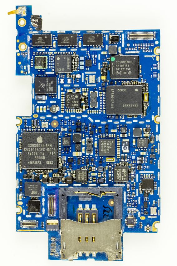
Drawback: NOR flash memory (top
image) on the IPhone 3G
More complex (=⇒ expensive) construction mainboard (bottom image)
Higher power consumption than NAND memory
Typically small capacities (≤ 32 MB)
Does not contain pages
The memory cells are grouped together to blocks
Typical block sizes: 64, 128 or 256 kB
No random access for erase operations
Erase operations can only be done for entire blocks
Fields of application
Industrial environment (e.g. automotive), storing the firmware of a
Images: Raimond Spekking.
computer system Wikimedia (CC-BY-SA-4.0)
Prof. Dr. Christian Baun – 4th Slide Set Operating Systems – Frankfurt University of Applied Sciences – WS2021 16/32Hard Disk Drives (HDD) Solid State Drives (SSD) RAID
NAND Memory
The memory cells are grouped to pages
Typical page size: 512-8192 bytes
Each page has it’s data line
Each block consists of a number of pages
Typical block sizes: 32, 64, 128 or 256 pages
Benefit:
Lesser data lines =⇒ requires < 50% of the surface area of NOR memory
Lower manufacturing costs compared with NOR flash memory
Drawback:
No random access =⇒ Poorer latency compared with NOR memory
Read and write operations can only be carried out for entire pages
Erase operations can only be carried out for entire blocks
Fields of application
USB flash memory drives,
SSDs, memory cards
Prof. Dr. Christian Baun – 4th Slide Set Operating Systems – Frankfurt University of Applied Sciences – WS2021 17/32Hard Disk Drives (HDD) Solid State Drives (SSD) RAID
Single/Multi/Triple/Quad-Level Cell
4 types of NAND flash memory
exist
QLC memory cells store 4 bits
TLC memory cells store 3 bits
MLC memory cells store 2 bits
SLC memory cells store 1 bit
SLC storage. . .
is most expensive
provides the best write speed
survives most program/erase
cycles
SLC memory survives approx. 100,000 - 300,000 program/erase cycles
MLC memory survives approx. 10,000 program/erase cycles
TLC and QLC memory survives approx. 1,000 program/erase cycles
Also memory cells exist, which survive millions of program/erase cycles
Prof. Dr. Christian Baun – 4th Slide Set Operating Systems – Frankfurt University of Applied Sciences – WS2021 18/32Hard Disk Drives (HDD) Solid State Drives (SSD) RAID
Wear Leveling
Wear leveling algorithms evenly distribute write operations
File systems, which are designed for flash memory, and therefore
minimize write operations, are e.g. JFFS, JFFS2, YAFFS and LogFS
JFFS contains its own wear leveling algorithm
This is often required in embedded systems, where flash memory is
directly connected
Prof. Dr. Christian Baun – 4th Slide Set Operating Systems – Frankfurt University of Applied Sciences – WS2021 19/32Hard Disk Drives (HDD) Solid State Drives (SSD) RAID
Latency of Hard Disk Drives
The performance of CPUs, cache and main memory is growing faster
than the data access time (latency ) of HDDs:
HDDs
1973: IBM 3340, 30 MB capacity, 30 ms data access time
1989: Maxtor LXTl00S, 96 MB capacity, 29 ms data access time
1998: IBM DHEA-36481, 6 GB capacity, 16 ms data access time
2006: Maxtor STM320820A, 320 GB capacity, 14 ms data access time
2011: Western Digital WD30EZRSDTL, 3 TB capacity, 8 ms data access time
2018: Seagate BarraCuda Pro ST14000DM001, 14 TB capacity, 4-5 ms data access time
CPUs
1971: Intel 4004, 740 kHz clock speed
1989: Intel 486DX, 25 Mhz clock speed
1997: AMD K6-2, 550 Mhz clock speed
2007: AMD Opteron Santa Rosa F3, 2.8 GHz clock speed
2010: Intel Core i7 980X Extreme (6 Cores), 3.33 Ghz clock speed
2018: AMD Ryzen Threadripper 2990WX (32 Cores), 3 Ghz clock speed
2020: AMD Ryzen Threadripper 3990X (64 Cores), 2.9 Ghz clock speed
The latency of SSDs is ≤ 1 µs =⇒ ≈ factor 100 better than HDDs
But the gap grows because of interface limitations and multiple CPU
cores
Further challenge
Storage drives can fail =⇒ risk of data loss
Enhance latency and reliability of HDDs and SSDs =⇒ RAID
Prof. Dr. Christian Baun – 4th Slide Set Operating Systems – Frankfurt University of Applied Sciences – WS2021 20/32Hard Disk Drives (HDD) Solid State Drives (SSD) RAID
Redundant Array of independent Disks (RAID)
The performance of the HDDs can not be improved infinitely
HDDs contain moving parts
Physical boundaries must be accepted
One way to avoid the given limitations in terms of speed, capacity and
reliability, is the parallel use multiple components
A RAID consists of multiple drives (HDDs or SSDs)
For users and their processes, a RAID behaves like a single large drive
Data is distributed across the drives of a RAID system
The RAID level specifies how the data is distributed
The most commonly used RAID levels are RAID 0, RAID 1 and RAID 5
Patterson, David A., Garth Gibson, and Randy H. Katz, A Case for Redundant Arrays of Inexpensive Disks (RAID), Vol. 17.
No. 3, ACM (1988)
Prof. Dr. Christian Baun – 4th Slide Set Operating Systems – Frankfurt University of Applied Sciences – WS2021 21/32Hard Disk Drives (HDD) Solid State Drives (SSD) RAID
RAID 0 – Striping – Acceleration without Redundancy
No redundancy
Increases only the data rate
Drives are partitioned into blocks of equal size
If read/write operations are big enough (> 4 or 8 kB), the operations
can be carried out in parallel on multiple drives or on all drives
In the event of a drive failure, not the entire data
can be reconstructed
Only small files, which are stored entirely on the
remaining drives, can be reconstructed (in theory)
RAID 0 should only be used when security is
irrelevant or backups are created at regular intervals
Prof. Dr. Christian Baun – 4th Slide Set Operating Systems – Frankfurt University of Applied Sciences – WS2021 22/32Hard Disk Drives (HDD) Solid State Drives (SSD) RAID
RAID 1 – Mirroring
At least 2 drives of the same capacity store identical data
If the drives are of different sizes, RAID 1 provides only the capacity of
the smallest drive
Failure of a single drive does not cause any data loss
Reason: The remaining drives store the identical data
A total loss occurs only in case of the failure of all drives
Any change of data is written on all drives
Not a backup replacement
Corrupted file operations or virus attacks take place
on all drives
The read performance can be increased by intelligent
distribution of requests to the attached drives
Prof. Dr. Christian Baun – 4th Slide Set Operating Systems – Frankfurt University of Applied Sciences – WS2021 23/32Hard Disk Drives (HDD) Solid State Drives (SSD) RAID
RAID 2 – Bit-Level Striping with Hamming Code Error Correction
Each sequential bit is stored on a different drive
Bits, which are powers of 2 (1, 2, 4, 8, 16, etc.) are parity bits
The individual parity bits are distributed over multiple drives
=⇒ increases the throughput
Was used only in mainframes
Is no longer relevant
Prof. Dr. Christian Baun – 4th Slide Set Operating Systems – Frankfurt University of Applied Sciences – WS2021 24/32Hard Disk Drives (HDD) Solid State Drives (SSD) RAID
RAID 3 – Byte-level Striping with Parity Information
Parity information is stored on a dedicated parity drive
Each write operation on the
RAID causes write operations on
the dedicated parity drive
=⇒ bottleneck
Was replaced by RAID 5
Payload drives Sum even/odd Parity drive
Bits are 0 + 0 + 0 =⇒ 0 =⇒ Sum is even =⇒ Sum bit 0
Bits are 1 + 0 + 0 =⇒ 1 =⇒ Sum is odd =⇒ Sum bit 1
Bits are 1 + 1 + 0 =⇒ 2 =⇒ Sum is even =⇒ Sum bit 0
Bits are 1 + 1 + 1 =⇒ 3 =⇒ Sum is odd =⇒ Sum bit 1
Bits are 1 + 0 + 1 =⇒ 2 =⇒ Sum is even =⇒ Sum bit 0
Bits are 0 + 1 + 1 =⇒ 2 =⇒ Sum is even =⇒ Sum bit 0
Bits are 0 + 1 + 0 =⇒ 1 =⇒ Sum is odd =⇒ Sum bit 1
Bits are 0 + 0 + 1 =⇒ 1 =⇒ Sum is odd =⇒ Sum bit 1
Prof. Dr. Christian Baun – 4th Slide Set Operating Systems – Frankfurt University of Applied Sciences – WS2021 25/32Hard Disk Drives (HDD) Solid State Drives (SSD) RAID
RAID 4 – Block-level Striping with Parity Information
Parity information is stored at a dedicated parity drive
Difference to RAID 3:
Not individual bits or bytes, but blocks (chunks) are stored
Each write operation on
the RAID causes write
operations on the
dedicated parity drive
Drawbacks:
Bottleneck
Dedicated parity
drive fails more
P(16-19) = Block 16 XOR Block 17 XOR Block 18 XOR Block 19
frequently
Seldom implemented, because RAID 5 does not face these drawbacks
The company NetApp implements RAID 4 in their NAS servers
e.g. NetApp FAS2020, FAS2050, FAS3040, FAS3140, FAS6080
Prof. Dr. Christian Baun – 4th Slide Set Operating Systems – Frankfurt University of Applied Sciences – WS2021 26/32Hard Disk Drives (HDD) Solid State Drives (SSD) RAID
RAID 5 – Block-level Striping with distributed Parity Information
Payload and parity
information are
distributed to all drives
Benefits:
High throughput
High security level
against data loss
No bottleneck P(16-19) = block 16 XOR block 17 XOR block 18 XOR block 19
Prof. Dr. Christian Baun – 4th Slide Set Operating Systems – Frankfurt University of Applied Sciences – WS2021 27/32Hard Disk Drives (HDD) Solid State Drives (SSD) RAID
RAID 6 – Block-level Striping with double distributed Parity Information
Functioning is similar to RAID 5
But it can handle the simultaneous failure of up to 2 drives
In contrast to RAID 5. . .
is the availability better, but the write performance is lower
is the effort to write the parity information higher
Prof. Dr. Christian Baun – 4th Slide Set Operating Systems – Frankfurt University of Applied Sciences – WS2021 28/32Hard Disk Drives (HDD) Solid State Drives (SSD) RAID
Summary of the RAID Levels
RAID n (number k Allowed Performance Performance
of drives) (net capacity) to fail (read) (write)
0 ≥2 n 0 (none) n∗X n∗X
1 ≥2 1 n − 1 drives n∗X X
2 ≥3 n − [log2 n] 1 drive variable variable
3 ≥3 n−1 1 drive (n − 1) ∗ X (n − 1) ∗ X
4 ≥3 n−1 1 drive (n − 1) ∗ X (n − 1) ∗ X
5 ≥3 n−1 1 drive (n − 1) ∗ X (n − 1) ∗ X
6 ≥4 n−2 2 drives (n − 2) ∗ X (n − 2) ∗ X
X is the performance of a single drive during read or write
The maximum possible performance in theory is often limited by the
controller and the computing power of the CPU
If the drives of a RAID 1 have different capacities, the net capacity of a RAID 1 is equal to the capacity of its smallest drive
Prof. Dr. Christian Baun – 4th Slide Set Operating Systems – Frankfurt University of Applied Sciences – WS2021 29/32Hard Disk Drives (HDD) Solid State Drives (SSD) RAID
RAID Combinations
Usually RAID 0, 1 or 5 is used
In addition to the popular RAID
levels, several RAID
combinations exist
At least 2 RAIDs are
combined to a bigger RAID
Examples
RAID 00: Multiple RAID 0 are connected to a RAID 0
RAID 01: Multiple RAID 0 are connected to a RAID 1
RAID 05: Multiple RAID 0 are connected to a RAID 5
RAID 10: Multiple RAID 1 are connected to a RAID 0 (see figure)
RAID 15: Multiple RAID 1 are connected to a RAID 5
RAID 50: Multiple RAID 5 are connected to a RAID 0
RAID 51: Multiple RAID 5 are connected to a RAID 1
Prof. Dr. Christian Baun – 4th Slide Set Operating Systems – Frankfurt University of Applied Sciences – WS2021 30/32Hard Disk Drives (HDD) Solid State Drives (SSD) RAID
Hardware / Host / Software RAID (1/2) Image Source: Adaptec
Hardware RAID
A RAID controller with a processor does the
calculation of the parity information and monitors
the state of the RAID
Benefit: Operating system independent
Adaptec SATA RAID 2410SA
No additional CPU load
Drawback: High price (approx. e 200)
Host RAID
Either an inexpensive RAID controller or the
chipset provide the RAID functionality
Usually only supports RAID 0 and RAID 1
Benefit: Operating system independent
Adaptec SATA II RAID 1220SA Low price (approx. e 50)
Drawback: Additional CPU load
Possible dependence of rare hardware
Prof. Dr. Christian Baun – 4th Slide Set Operating Systems – Frankfurt University of Applied Sciences – WS2021 31/32Hard Disk Drives (HDD) Solid State Drives (SSD) RAID
Hardware / Host / Software RAID (2/2)
Software RAID
Linux, Windows and MacOS allow to connect drives to a RAID without a
RAID controller
Benefit: No cost for additional hardware
Drawback: Operating system dependent
Additional CPU load
Example: Create a RAID 1 (md0) with the partitions sda1 and sdb1:
mdadm --create /dev/md0 --auto md --level=1
--raid-devices=2 /dev/sda1 /dev/sdb1
Obtain information about any software RAID in the system:
cat /proc/mdstat
Obtain information about a specific software RAID (md0):
mdadm --detail /dev/md0
Remove partition sdb1 and add partition sdc1 to the RAID:
mdadm /dev/md0 --remove /dev/sdb1
mdadm /dev/md0 --add /dev/sdc1
Prof. Dr. Christian Baun – 4th Slide Set Operating Systems – Frankfurt University of Applied Sciences – WS2021 32/32You can also read