A RRR RedBox for Safety-Critical Networked Embedded Systems
←
→
Page content transcription
If your browser does not render page correctly, please read the page content below
A RRR RedBox for Safety-Critical Networked
              Embedded Systems

                 Michael Costa, Arnaldo Oliveira, Paulo Pedreiras

                   DETI/IT/University of Aveiro, Aveiro, Portugal
            michaelccosta@live.ua.pt, {arnaldo.oliveira,pbrp}@ua.pt

        Abstract. Networked Embedded Systems (NES) are used in a broad
        range of application domains, from automation and industrial machin-
        ery to vehicles, medical equipment. Many NES are intrinsically safety-
        critical, meaning that a system failure may have catastrophic results,
        e.g., damage to expensive equipment or endanger human lives. This type
        of systems requires high levels of reliability, which can be achieved using
        fault tolerance techniques. Different Ethernet redundancy mechanisms
        have been developed, such as RSTP, HSR, PRP and RRR.
        RRR is a recently proposed protocol, based on the use of multiple virtual
        rings, that is fully distributed and allows recovery times in the order
        of 1ms. This paper presents the implementation of a redundancy box
        (RedBox) for this protocol that simplifies the network deployment and
        maintenance. The RedBox was implemented using FPGA technology
        and experimentally validated. The experimental results obtained show
        the feasibility and correction of the approach, being possible to react to
        errors in less than 1ms.

1     Introduction

Networked Embedded Systems (NES) are currently found in a wide range of do-
mains, from automotive to aerospace, process control and manufacturing indus-
try. In these domains, applications range from embedded command and control
systems to image processing, monitoring, human-machine interfacing, etc, and, in
many cases, present specific requirements in terms of predictability, timeliness,
precedence constraints and availability. The non-respect of such requirements
can impact negatively on the quality of the control action in distributed com-
puter control systems or on the quality of the observation of the system state in
distributed monitoring/supervision systems.
    To deliver the adequate quality of service for these applications, during the
last two decades several special-purpose networks have been developed. They are
generically called fieldbuses and are particularly suited for supporting frequent
    This work was partially supported by the Portuguese Government through FCT
    - “Fundação para a Ciência e a Tecnologia” in the scope of project Serv-CPS -
    PTDC/EEA-AUT/122362/2010

                                          408
exchanges of small amounts of data under time, precedence and dependabil-
ity constraints [13]. Some of the most well known examples existing today are
PROFIBUS, WorldFIP, P-Net, Foundation Fieldbus, TTP/C, CAN and CAN-
based systems such as DeviceNet.
    The quantity, complexity and functionality of the nodes within NES have
been steadily increasing. Because of this evolution, the amount of information
that must be exchanged over the network has also increased, both for configura-
tion and for operational purposes. The increase on the amount of data exchanged
between nodes is reaching, in many application areas, the limits that are achiev-
able using traditional fieldbuses due to the constraints on bandwidth. Machine
vision, and its growing use in many areas, is just one example of a killer appli-
cation for those systems. Therefore, other alternatives are required to support
higher bandwidth demands while keeping the main requirements of a real-time
communication system: predictability, timeliness, bounded delays and jitter.
   Recently, Ethernet gained and increasing interest from the academic and in-
dustrial communities, due to its large bandwidth, cheap silicon, high availability,
easy integration with Internet and clear path for future expandability [8]. The
advantages of Ethernet technology are so clear that, currently, NES are experi-
encing a transition from traditional systems, based on fieldbuses and proprietary
communication solutions, to network oriented systems utilizing Real-Time Eth-
ernet (RTE) technologies, as documented in a recent ARC study [7].
    Many of the application areas where Ethernet technologies are starting to be
used are safety-critical, requiring high levels of robustness and availability, typ-
ically implying the use of redundancy technologies. There are several protocols
that provide redundancy on Ethernet networks, such as Rapid Spanning Tree
Protocol (RSTP) [5], High-Availability Seamless redundancy protocol (HSR) [3],
Parallel Redundancy Protocol (PRP) [2], Transparent Interconnection of Lots
of Links (TRILL) [9] or Rapid Ring Recovery (RRR) [11].
    RRR is a recently proposed protocol, based on the use of multiple virtual
rings, that is fully distributed, allows recovery times in the order of 1ms, is
easily implementable and does not require a duplicated infrastructure. This pa-
per presents the implementation of a redundancy box (RedBox) for the RRR
protocol. The RedBox offers a standard Ethernet interface to the nodes locally
attached to it, providing a seamless integration of the redundancy architecture.
Furthermore, the RedBox allows the direct formation of the network, without
depending on switches, therefore simplifying the network deployment and main-
tenance.
    The remaining of this paper is organized as follows. Section 2 presents an
overview on redundancy protocols for Ethernet. Section 3 contains a detailed
description of the implementation fo the RRR RedBox. Section 4 presents a set
of experimental results that show the feasibility and correctness of the proposal.
Finally, Section 5 includes a summary of the contributions and presents the main
conclusions of this work.

                                        409
2 Related work
Critical networked embedded systems require that the communication infras-
tructure operates at all times to avoid catastrophic consequences. Redundancy
is a mean to achieve higher levels of system availability. Over the years, several
approaches to the problem of network redundancy have been developped, with
different aims, principles of operation, performance and cost.
The most well known network redundancy protocol is Rapid Spanning Tree
Protocol (RSTP) [5]. RSTP is an evolution of the Spanning Tree Protocol (STP),
which is a network protocol developed to generic data networks that ensures a
loop-free topology for bridged Ethernet local area networks. The function of
STP is to prevent loops, creating a logical tree topology out of any physical
topology. RSTP is backwards-compatible with standard STP, providing a much
faster convergence after a topology change. Thus, in RSTP networks there is
only one active communication path between any two nodes. Upon a failure of
a cable or a switching device, RSTP calculates a new tree and re-establishes
the communication. The reconfiguration time, defined as the time that elapses
between the occurrence of a failure and the completion of the reconfiguration
process, may take from hundreds of milliseconds to seconds, depending on the
size and topology of the network [12].
The recovery time provided by RSTP is too large for many application areas,
such as automation systems. The IEC 62439 High Availability Automation Net-
works standard [1] was developed to address this limitation, specifying several
redundancy solutions that address specifically the industrial systems require-
ments.
IEC 62439-1 defines the nomenclature, how to compute the reliability and
availability and how to compute the recovery time of RSTP. These guidelines
allow to reduced dramatically the recovery time of RSTP to some tens of mil-
liseconds for ring topology networks, which is a value already suitable to less
stringent industrial applications.
IEC 62439-2 specifies the Media Redundancy Protocol (MRP), a ring pro-
tocol supported by several industrial equipment manufacturing companies. This
protocol offers typical recovery times of the order of 100ms, which can be lowered
down to 10 milliseconds for ring topologies of limited size.
IEC 62439-3 offers two seamless protocols with zero recovery time. PRP
offers zero recovery time by using two parallel networks simultaneously. HSR is
based in a ring topology where data is sent in both directions in the ring at the
same time. Each node uses its source address and a sequence number, coded in
a dedicated tag in the packet, to detect frames that have crossed the whole ring
and thus remove duplicated packets.
IEC 62439 contemplates other protocols, such as CRP and BRP, supported
by industrial players such as Fieldbus Foundation and ODVA, with typical re-
covery times in the order of 400ms and 10ms.
The IEEE 802.1aq standard is an amendment to the “Virtual Bridge Local
Area Networks” IEEE standard (IEEE Std 802.1Q-2011), adding Shortest Path
Bridging. SPB uses shortest path trees (SPTs) instead of the spanning trees used
410by STP and RSTP. SPB calculates the shortest path trees using the Intermediate
System to Intermediate System (IS-IS) routing protocol. It uses multiple paths,
so the bandwidth utilization is much better than in RSTP networks. SPB’s main
focus are meshed topologies, as the ones used in data centres, supporting load
balancing.
TRILL [9] is a layer two forwarding protocol that replaces the STP by using
IS-IS routing to distribute link state information and calculate shortest paths
through the network. TRILL data packets and IS-IS routing packets are ex-
changed between Routing Bridges, which automatically discover each other us-
ing IS-IS Hello frames. Similarly to SPB, TRILL addresses meshed topologies,
as the ones used in data centres and supports load balancing.
Rapid Ring Recovery (RRR) [11] is a recent proposal that describes a ring
network redundancy solution, based on multiple virtual lans, that allows recovery
times below 1ms. This protocol is completely decentralized, has no single point-
of-failure, does not depend on global control messages than may take a long
time to propagate and can be easily integrated with existing hardware. These
advantages have motivated the work presented in this paper.
3 RRR RedBox Implementation
As mentioned in the previous section, the RRR protocol is fully distributed, al-
lows very short recovery times and does not require a duplicated infrastructure,
turning it very appealing to use in industrial networks. The implementation of
this protocol described in the literature ([11]) is based on FPGA technology,
depending on COTS switches supporting 802.1Q. This set-up is, in many ap-
plication scenarios, cumbersome and expensive. Therefore, in this section it is
presented the implementation of a RRR RedBox that includes switching services.
The RedBox offers a standard Ethernet interface to the nodes locally attached
to it, providing a seamless integration of the redundancy architecture. Further-
more, the RedBoxes can be directly connected to each other, without needing
switches, therefore simplifying the network deployment and maintenance and
reducing the cost. This section firstly presents a detailed description of the RRR
protocol, followed by the presentation of the RedBox design.
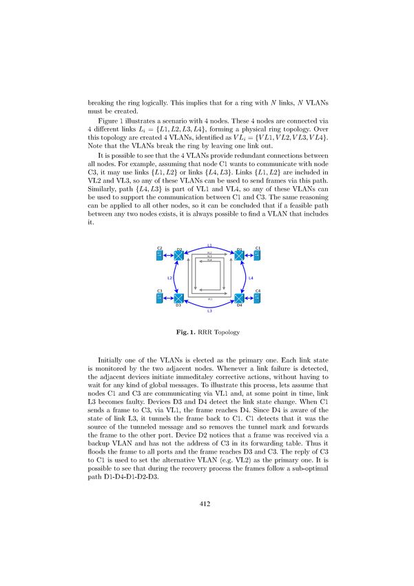
3.1 The RRR protocol
The RRR protocol [11] was developed in order to improve the recovery time of a
fault within industrial networks based on a ring topology. The recovery scheme
is completely decentralized and, upon a fault, only the two nodes adjacent to the
fault are involved in detecting it and taking the corrective actions. This allows
obtaining recovery times below 1ms.
RRR makes an intelligent use of multiple virtual rings to prevent infinite
frame looping and broadcast storms, which may flood the network when messages
with unknown MAC addresses are transmitted by a node. To this end, RRR
creates several VLANs, each one connecting all network nodes but one, therefore
411The re-routing process above described implies that, upon a link failure,
frames are tunneled back to the same port where they came from. This behavior
is not allowed in the normal operation of Ethernet networks, since it can cause
corruption of the forwarding tables. In fact, if a frame is directly re-routed to its
destination, all intermediate nodes would associate the source MAC address to
the wrong port. To avoid the corruption of the forwarding tables, messages are
encapsulated using MAC-in-MAC (Provider Backbone Bridges, IEEE 802.1ah-
2008), depicted in Fig. 2, and address learning is disabled in the path between
the node adjacent to the link that failed and the source node. A more detailed
presentation of the whole recovery and reconfiguration process can be found in
[11].
Fig. 2. MAC-in-MAC header
3.2 RRR RedBox Design
Figure 3 shows the internal architecture of the RedBox. Each RedBox has three
Ethernet Ports. Two of those ports are used to connect the RedBox to the ring
(ring ports) and the third one is a local port used to connect a node to the ring.
It is important to stress that the RedBox provides a transparent connection to
the RRR ring, therefore offering a standard Ethernet interface at its local port.
After the Ethernet ports there is a PHY which communicates with the MAC
through the MII protocol. The MAC used in this implementation is a intellec-
tual property core distributed by Xilinx, the Tri-Mode Ethernet Media Access
Controller [6]. This MAC has a client interface composed by control signals and
a 8 bit wide data bus. Each MAC has a reception (Rx) and a transmission (Tx)
interface. All Rx interfaces are linked to a multiplexer (MUX) that allows the
serialization of the frame processing. Between the MAC of the local port and
the MUX there is a block which adds the MAC-in-MAC header to frames sent
to the ring and removes it from the received ones.
413Fig. 3. RedBox Internal Architecture
After the MUX there is a block that implements the ring management. This
block analyzes the header of the incoming frames and decides if and to which
port(s) frames are forwarded. This decision is made according to the id of the
RedBox, the VLAN id contained in the frame, the existence of faults on adjacent
links and the forwarding table. The forwarding decisions are coded as a state
machine and the forwarding decisions are communicated to the demultiplexer
block (DEMUX) via a set of appropriate control bits.
The DEMUX block receives the frames and, according to the control bits,
forwards them to the correct port. Frames can be simultaneously forwarded to
more than one port, a feature that is useful when the same frame has to be
forwarded to the ring and to the local ports. Between the DEMUX and each
one of the interfaces of the rings ports there is a Keep Alive block, responsible
for sending keep alive frames. These frames are sent periodically, so this block
contains a configurable timer module. Each time a frame is sent to a ring port,
the respective timer is restarted.
The flowchart presented in Fig. 4 illustrates the global operation of the Red-
Box. Whenever a frame is received, its header is verified. The right path (Tunnel
bit cleared and EtherType = 0x9000) corresponds to the reception of a keep alive
frame. In this case the timeout counter is reset and the frame dropped. The left
path (Tunnel bit set and EtherType = 0x9000) corresponds to the reception of
a tunneled frame and is a consequence of a link error. B-SA is the address of
the switch who inserts the frame into the ring. If the address of the switch who
receives the frame matches the address B-SA that means that the packet was
sent back and arrived at the source node. In this case it is necessary to remove
the tunneling and forward it to the other ring port. If the address does not
match B-SA it means that the packet is in its way to the source node, and thus
is simply forwarded to the other ring port. Finally, the central path corresponds
to the reception of a normal data packet. In this case the device firstly updates
the forwarding tables (using the source address field), determines to which port
the frame should be forwarded (using the destination address field) and finally
414Fig. 4. RRR block flowchart
sends the frame to the right ring port. Note that, depending on the information
obtained from the forwarding table and on link state, it may be necessary to
modify the header of the frame and the control bits, before sending it.
4 Experimental Results
The RedBox design presented in Section 3.2 was instantiated on a Starter Board
with a MX1 Module manufactured by Enclustra [4]. To validate the implementa-
tion and evaluate its performance, it was used the experimental set-up, depicted
in Fig. 5, composed by three RedBoxes (RB1,RB2 and RB3). All the Ethernet
ports are configured to full-duplex operating at 100Mbps. KeepAlive messages
are generated every 200µs and the timeout value was set to 225µs.
RedBoxes RB1 and RB3 have been selected as the end-nodes for all the ex-
periments. To allow high accuracy measurements, these RedBoxes have been
instrumented with a dedicated block containing a user-configurable traffic gen-
erator [10] and a sniffer. The sniffer block uploads the captured data (i.e., times-
tamps) to an external computer via a UART connection. The RedBoxes are also
instrumented to allow the injection of faults in links L1 and L3.
415Fig. 5. Network Topology
The first experiment aimed at establishing a baseline and consisted in sending
periodic messages from RB1 to RB2, without errors, and measure the arrival
time. The frame sizes were varied from 64B to 1460B and the periods from 20µs
to two seconds. Fig. 6 shows the results obtained for 132B messages sent with a
period of 145µs. No messages are lost and the maximum jitter is around 10µs.
The other traffic configurations shown identical results, so it can be concluded
that the jitter is fairly independent of the frame’s periods and sizes.
Fig. 6. Frame interarrival time in the absence of faults
In the following experiments the fault injector was configured to generate
alternate faults on links L1 and L3, with a periodicity of 12ms. During this
period each one of these links was alternatively unavailable for 4ms, and during
the remaining 4ms both links were available.
416The first test scenario was borrowed from [11], consisting in a periodic frame
with a period of 115µs and a size of 132 bytes, corresponding to a bandwidth of
10Mbps.
Fig. 7. Inter-arrival time histogram for 115µs, 132Bytes traffic
As mentioned above, the timeout value for considering a link as faulty is set to
225µs. It should also be recalled that the recovery procedure is triggered by the
reception of the first data frame that follows the instant when the link becomes
faulty. Therefore, the recovery time is lower bounded by the timeout value, a
situation that happens when the last successful transmission occurs immediately
before the beginning of the unavailability period, and the first recoverable trans-
mission occurs immediately after the end of this period. The upper bound is
given by the timeout value plus two frame periods. This scenario happens when
the last successful transmission occurs one period before the beginning of the
unavailability period, and the first recoverable transmission occurs one period
after the end of the unavailability period. In both cases it must be added the
eventual difference between the number of links crossed by both VLANs and
the non-optimal path during the transitory period, plus the processing time in
each node. In the present case the inter-arrival time should be comprised between
225µs and 471µs, ignoring the processing time. These values are compatible with
the ones obtained experimentally, as shown in Fig. 7. The upper bound was not
measured experimentally, probably due to the limited number of experiments
carried out.
A third experiment consisted in measuring the number of lost packets with
different traffic configurations, corresponding to bandwidths comprised between
10Mbps and 60Mbps, with frame sizes of 136 bytes and 1440 bytes. The obtained
results are shown in Tab. 1. The first column contains the frame size, in bytes, the
second column the period, in µs, the third column the corresponding bandwidth,
in Mbps, the fourth column reports the number of message instances, the fifth
417column the number of lost messages, the sixth the number of faults and, finally,
the seventh column the average number of lost message per fault.
C(B) T (µs) BW (Mbps) # Tx # Lost # Faults Lost per fault
1460 1177 10 1020 20 75 0.27
1460 785 15 1022 22 50 0.44
1460 588 20 1021 21 37 0.57
1460 471 25 1023 23 30 0.77
1460 392 30 1022 22 25 0.88
1460 294 45 1020 20 19 1.05
1460 235 50 1022 22 15 1.47
1460 196 60 1018 18 12 1.50
132 115 10 1013 13 8 1.63
132 77 15 1011 11 5 2.20
132 57 20 1014 14 4 3.50
132 46 25 1011 11 3 3.67
132 38 30 1008 8 2 4.00
132 26 45 1016 16 2 8.00
132 23 50 1008 8 1 8.00
132 19 60 1011 11 1 11.00
Table 1. Lost packets
The results shown in Tab. 1, particularly the right column that quantifies the
average number of lost packets per link fault, show a strong correlation between
the number of lost packets and the frame’s period, as expected. In fact, frames
with short periods may have several instances affected by undetected errors. For
instance, when a link becomes faulty a message stream with a period of 115µs has
one or two instances affected by undetected faults. Messages with period higher
than the link timeout value may have at most one message instance affected by
undetected faults. Furthermore, the higher the period the lower the probability
of having one instance affected by the 225 µs fault detection window.
Summarizing, the obtained experimental results are consistent with the ex-
pectations and compatible with the ones reported in [11], particularly in what
concerns the fault detection latency (225 µs vs 294 µs). The number of faults is
not directly comparable due to the utilization 1Gbps links in [11] and 100Mbps
links in this work.
5 Conclusions
Ethernet-based networks are increasingly used in NES. Many of these NES are
intrinsically safety-critical. This type of systems requires high levels of reliability
418and integrity, which can only be achieved using fault tolerance techniques. RRR
is a recently proposed protocol, based on the use of multiple virtual rings, that
is fully distributed and allows extremely short recovery times.
This paper presented the design of a RedBox that implements the RRR pro-
tocol. This RedBox offers a standard Ethernet interface to local nodes, simplifies
the network deployment and maintenance and is less expensive than the original
design, since allows the direct formation of the ring, without the need of any
additional hardware, namely switches.
The RedBox was implemented using FPGA technology and experimentally
validated. The results obtained prove that it is possible to implement the RRR
protocol in simple FPGA hardware and achieve recovery times compatible with
the ones that are attained with the original proposal, which requires additional
hardware.
The RedBox presented in this work strictly follows the RRR protocol as
described in the literature. However, during this work we have realized that some
of the actions carried out in response to faults arise from the use of switches.
Since switches are no longer necessary on the architecture proposed in this work,
as future work it will be investigated the possibility of simplifying the operation
of the RRR protocol, to reduce its complexity and improve its performance.
References
1. IEC 62439. High Availability Automation Networks. International Electrotechnical
Commission, 2010.
2. International Electrotechnical Commission, IEC 62439-3 Clause 4.
3. International Electrotechnical Commission, IEC 62439-3 Clause 5.
4. Mars MX1, Xilinx c Spartan c -6 LX FPGA Module.
5. Standard IEEE 802.1D. MAC Bridges. IEEE 2004.
6. Xilinx, LogiCORE R Tri-Mode MAC v4.4 User Guide., 2010.
7. ARC Advisory Group. Industrial Ethernet-Based Devices - market research study,
2011.
8. J-D Decotignie. The Many Faces of Industrial Ethernet [Past and Present]. In-
dustrial Electronics Magazine, IEEE, 3(1):8–19, 2009.
9. R. Perlman et al. Internet Engineering Task Force (IETF) Request for Comments:
6325.
10. Rafael Gouveia. Injector de Tráfego de Pacotes Ethernet em VHDL para FPGA
Atlys. DETUA, 2013.
11. Minh Huynh, Stuart Goose, Prasant Mohapatra, and Raymond Liao. RRR: Rapid
Ring Recovery Submillisecond Decentralized Recovery for Ethernet Ring. IEEE
Transactions on Computers, 60(11):1561–1570, 2011.
12. G. Prytz. Network Recovery Time Measurements of RSTP in an Ethernet Ring
Topology. In Emerging Technologies and Factory Automation, 2007. ETFA. IEEE
Conference on, pages 1247–1253, 2007.
13. Jean Pierre Thomesse. Fieldbuses and Interoperability. Control Engineering Prac-
tice, 7(1):81 – 94, 1999.
419You can also read