A study of the effect of swirling airflow on fuel spray characteristics under low pressure atmosphere
←
→
Page content transcription
If your browser does not render page correctly, please read the page content below
ICLASS 2021, 15th Triennial International Conference on Liquid Atomization and Spray Systems, Edinburgh, UK, 29 Aug. - 2 Sept. 2021
A study of the effect of swirling airflow on fuel spray characteristics
under low pressure atmosphere
Kenichi SHIMIZU*1, Takehiko SEO1, Masato MIKAMI1
1
Graduate School of Sciences and Technology for Innovation,
Yamaguchi University, Ube, Japan
*Corresponding author e-mail : a022vdu@yamaguchi-u.ac.jp
ABSTRACT
Improving engine restart performance at high altitudes is essential to protect the safety of
aircraft. This study investigated the fuel spray characteristics in a low-pressure atmosphere
field with swirling air flow, focusing on high-altitude reignition of aircraft engines. Silicone oil,
which has similar physical properties to jet fuel, was used as the simulated fuel. In addition, a
swirl was used to apply a swirling air flow to the spray. The experiment was conducted in a
pressure vessel with an internal pressure of 0.025 MPa to simulate the atmospheric pressure
at high altitude. The droplet size distribution of the spray was measured using PDPA, and the
liquid film breakup process and the behavior of the droplets were obtained by the short-backlit
method with a high-speed camera and a pulsed diode laser light source. By increasing the
swirling air flow rate, the droplet size distribution of the spray decreased the number of small
droplets with a diameter of 30 μm or less, and the number of droplets increased toward the
circumference. Regarding the liquid film behavior, it was found that the liquid film shape
changed to a spindle type as the swirling air flow rate increased.
Keywords: Spray characteristics, Swirling air flow, Breakup process,
Low pressure atmosphere
_________________________________________________________________________
1 INTRODUCTION
Global aircraft demand continues to grow, and air passenger transport is expected to more
than double over the next 20 years(1). Aircraft engines are being actively developed in
response to such aircraft demand, and this development includes low fuel consumption,
improvement of thermal efficiency and propulsion efficiency, and noise reduction. Among them,
improving high-altitude reignition performance is extremely important for protecting the safety
of aircraft.Originally, ignition is performed in a high pressure atmosphere, but if the engine
stops while flying over 30,000 ft, the pressure in the combustion chamber will be in a low
pressure atmosphere equivalent to 0.025 MPa of the outside air, and reignition is expected to
be difficult due to unusual fuel spray characteristics. Since optimum premixture formation is
required for reliable ignition, it is important to elucidate the spray structure in the previous
stage and the atomization mechanism in a low-pressure atmosphere that leads to it. Neya
and Sato(2) investigated the effect of ambient air pressure on spray characteristics, and
reported that the droplet diameter becomes large and the cause is the liquid film thickness
when the ambient air pressure is lower than atmospheric pressure.Fraser (3) also studied
under the same experimental conditions as described above, and reported that the liquid film
splitting morphology changes and the droplet diameter increases under a low-pressure
atmosphere. According to Choi et al.(4) who investigated the spray characteristics of actual fuel
and water, kerosene was 20 m smaller in droplet diameter than water. Lefebvre(5)
investigated the spray characteristics associated with changes in the kinematic viscosity of
the liquid and reported that the droplet diameter decreases when the kinematic viscosity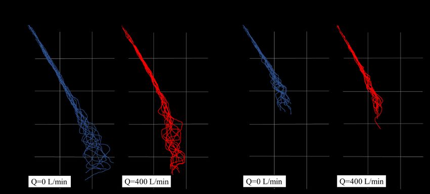
ICLASS 2021, 15th Triennial International Conference on Liquid Atomization and Spray Systems, Edinburgh, UK, 29 Aug. - 2 Sept. 2021

       decreases at the outer edge of the spray. This indicates that the spray shape and the
       generated droplets differ due to the difference in the physical property values of the liquid even
       under the same conditions.
         Therefore, in this study, silicone oil with a similar surface tension value was used as the jet
       fuel simulated liquid in a low-pressure atmosphere, and the temperature of the silicone oil was
       changed to control the kinematic viscosity before spraying. This study investigated the fuel
       spray characteristics by supplying a swirling air flow to the spray liquid to create an
       environment that simulates the actual machine.

       2 EXPERIMENTAL APPARATUS AND METHOD
       2.1 Experimental apparatus
         Figure 1 shows a schematic of the experimental apparatus.A stainless steel pressure-
       resistant container (SUS304, diameter 216.3 mm, height 400 mm) was used as the space for
       spraying the test liquid. To supply the test liquid, the container containing the test liquid is filled
       with nitrogen gas adjusted by a regulator (YUTAKA, FRILS-OP) and a pressure gauge (Daito
       Keiki Seisakusyo Co., Ltd., TYPE-AT) and pressurized. The injection pressure Pinj, was
       constant at 1.0 MPa. A single-hole spiral injection valve (Delavan, TYPE WDA angle 60°
       nozzle number 2.0) and a swirler (outer diameter 70 mm, inner diameter 36 mm, blade angle
       45°, number of blades 16, blade thickness 1 mm, swirl number 0.78) were attached inside
       the pressure-resistant container in which the spray is formed.The swirling direction of the
       liquid and the swirling air direction by the swirler are opposite. The swirling air flow was
       supplied by opening valve 1 while the vacuum pump (SHINKO SEIKI Co., Ltd., SW-50S)
       shown in Fig. 1 was operating. The measurement of the swirling air flow rate at that time was
       adjusted while checking with the flow sensor for the amplifier-separated aircraft (KEYENCE
       Co., Ltd., FD-A600) and the amplifier unit (KEYENCE Co., Ltd., FD-V40A). The pressure
       chamber was depressurized by a vacuum pump (SHINKO SEIKI Co., Ltd., SW-50S). The
       pressure of the inside of the chamber, ambient pressure Pamb, was measured using a vacuum
       gauge (OMRON Co., Ltd., E8F2-AN0C) which was connected to the pressure chamber by a
       stainless steel tube. In this study, Pamb was 0.025 MPa・abs, and the swirling air flow was
       supplied at 400 L / min in that state.

                                              Fig.1 Experimental apparatus
ICLASS 2021, 15th Triennial International Conference on Liquid Atomization and Spray Systems, Edinburgh, UK, 29 Aug. - 2 Sept. 2021
Table 1 Difference in physical characteristics between jet fuel and silicone oil
Surface tension Kinematic viscosity Density
[mN/m] [mm2/s] [g/cm3]
JET-A [265K] 25 8.5 0.7753
Silicone oil [298K] 24.4 15 0.9932
2.2 Jet fuel simulated liquid
In this experiment, it is necessary to use a liquid close to the physical properties of jet fuel
in order to simulate the test liquid as jet fuel (JET-A). Therefore, silicone oil (Shin-Etsu
Chemical Co., Ltd., KF-56A), whose surface tension value is close to that of jet fuel and whose
kinematic viscosity can be easily controlled, was used as the test liquid. Table 1 shows the
difference in each physical property value. Kanda(6) investigated the dependence of surface
tension and kinematic viscosity with temperature changes of silicone oil, and reported that the
surface tension value was almost the same between the temperatures of 298 K and 313 K,
but the kinematic viscosity value changed from 13.8 mm2 /s to 8.5 mm2 / s, which is equivalent
to jet fuel. Based on this result, in this study, the tube cover heater (Tokyo Institute of
Technology, SRX-6.35-05) was used to heat the supply pipe immediately before the pressure-
resistant container to heat the silicone oil flowing inside the pipe, to lower the kinematic
viscosity value.
2.3 Experimental method and conditions
The spray shape was visualized by the short-backlit method. The pulsed diode laser light
source(Cavitar Ltd., CAVILAX smart laser unit) is dimmed with a light amount reduction filter
(Kenko Tokina Co., Ltd., MC Filter, ND400) and irradiated to the spray as a backlight, and the
transmitted light is emitted by a high-speed camera (Vision Research Inc., Phantom VEO 710).
These synchronizations were performed by directly inputting the trigger signal output from the
high-speed camera to the control unit of the pulsed diode laser light source (Cavitar Ltd.,
CAVILAX control unit). The frame rate for shooting was set to 7,500 fps.
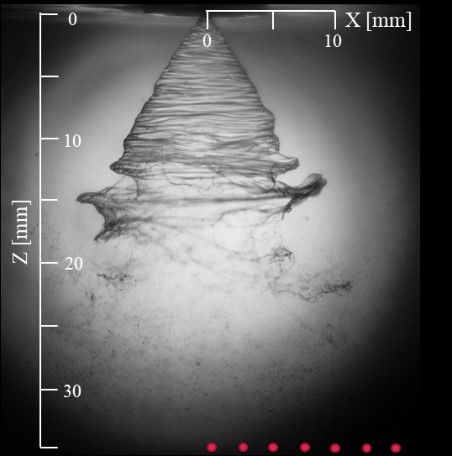
A Phase Doppler Particle Analyzer (PDPA)(TSI / Aerometrics, 2D-PDPA) shown was used
to measure the diameter of the sprayed droplets. In this experiment, an Ar ion laser with a
wavelength of 514 nm was used to measure the point downstream from the hole at Z = 35
mm and the radial direction from the hole at X = 0 to 15 mm at 3 mm intervals. The
measurement points are shown in red plots in the image in Fig. 2. By installing the transmitter
and receiver on an L-shaped rail attached to a traverse device (Chuo Seiki Co., Ltd., ADSL-
230-C2P). Their focal length is 500 mm. The beam intersection angle is 5 ° . PDPA
measurement was completed when 10000 droplets were measured or when 60 seconds
passed at each measurement point.
Fig.2 PDPA measurement pointsICLASS 2021, 15th Triennial International Conference on Liquid Atomization and Spray Systems, Edinburgh, UK, 29 Aug. - 2 Sept. 2021
3 RESULTS AND DISCUSSIONS
3.1 Effect of kinematic viscosity on spray shape
Figure 3 shows the difference in spray shape and liquid film length between 298K and
313K silicone oil under a low pressure atmosphere (Pamb = 0.025 MPa・abs). The average
value of the liquid film length shown in the red plot in the figure was obtained from 10
consecutive spray images. Since there is a significant difference in the liquid film length
between the two kinematic viscosities, the kinematic viscosity value will have a large effect on
the liquid film length. In a viscous fluid, the kinematic viscosity value affects the shear force
between gas and liquid, and the higher kinematic viscosity takes a long time to break up, so
the liquid film will be longer. In addition, in the spray shape of = 8.5 mm2 / s, a spiral wave
from the upper right to the lower left of the liquid film can be observed. This wave is probably
due to the slot in the injection valve before injection. Since low kinematic fluid is easily affected
by external force, it is considered that a velocity difference occurs inside the liquid due to the
force in the swirling direction of the slot, and a spiral wave is generated.
Fig.3 Difference in liquid film length for different kinematic viscosities
3.2 Effect of swirling air flow on spray shape
Figure 4 shows the spray shape at = 13.8 mm2 / s when the swirling air flow is not applied
and when 400 L / min is applied. When a swirling air flow is applied, the liquid film shape
changes to a spindle shape. The length of the liquid film also extends in the downstream
direction. Because the swirling direction given to the spray and the swirling direction of the
swirling air flow are in opposition, in the downstream part of the liquid film that is easily affected
by the swirling air flow, the development in the radial direction of the spray is suppressed due
to the relative velocity between gas and liquid, and the shape changes to a spindle type. It is
also considered that the development in the direction of the spray axis was promoted and
stretched thinly. Figure 5 shows the spray shape when swirling air flow is not applied and when
400 L/min is applied at = 8.5 mm2/s. There is no significant difference in the liquid film shape
and liquid film length even when a swirling air flow is applied. It is considered that this is
because the liquid film breaks up before being affected by the swirling air flow while
maintaining a strong inertial force at the upper part of the liquid film. Figure 6 shows a trace of
the outer edge of the liquid film when the swirling air flow rate is changed at each kinematic
viscosity in order to investigate the liquid film behavior in time series. The trace shown in Fig.
6 was obtained from 10 consecutive spray images. When = 13.8 mm2 / s, the fluctuation
width of the liquid film becomes smaller due to the swirling air flow supply. In addition, there is
no significant difference in the injection angle θ1 near the injection port at this time. Similarly,ICLASS 2021, 15th Triennial International Conference on Liquid Atomization and Spray Systems, Edinburgh, UK, 29 Aug. - 2 Sept. 2021
when = 8.5 mm2 / s, the fluctuation width of the liquid film becomes smaller by applying a
swirling air flow. In addition, there is no significant difference in the injection angle θ2 near the
injection port. The waviness of the liquid film surface in Fig. 6 can be confirmed under any
conditions regardless of the presence or absence of swirling air flow, and it is considered that
the influence of Kelvin-Helmholtz Instability (KHI) caused by the speed difference between the
ambient air and the liquid film is dominant. Considering the KHI, the instability and the
fluctuation width of the liquid film became smaller because the gas-liquid velocity difference
decreased due to the swirling air flow supply.
(a) Q=0 L/min (b) Q=400L/min
Fig.4 Typical images of spray shape for different swirling air flow rates [=13.8 mm2/s]
(a) Q=0 L/min (b) Q=400L/min
Fig.5 Typical images of spray shape for different swirling air flow rates [=8.5 mm2/s]
(a) =13.8 mm2/s (b) =8.5 mm2/s
Fig.6 Liquid film behavior for different kinematic viscositiesICLASS 2021, 15th Triennial International Conference on Liquid Atomization and Spray Systems, Edinburgh, UK, 29 Aug. - 2 Sept. 2021
3.3 Droplet size distribution
Figure 7 shows the droplet size distribution of droplets measured per unit time using PDPA
under both conditions of swirling air flow Q = 0 L / min and 500 L / min. Under the condition of
Q = 0 L / min, the droplet size distribution at X = 0, 3 mm has a peak around 25 μm, and at X
= 6, 9 mm, the number of droplets increases and the peak is around 15 μm. It moved to the
microdroplet side. It was confirmed that the number of droplets decreased and the peak
increased to 40 μm at X = 12 and 15 mm. Under the condition of Q = 500 L / min, the droplet
size distribution at X = 0 and 3 mm is almost unchanged, and the droplets near the spray
center are not affected by the swirling air flow at Z = 35 mm. At X = 6,9 mm, the peak was
around 30 μm. As compared with the result at the same position of Q = 0 L / min, the number
of droplets decreased overall, and the number of droplets with a diameter of 30 μm or less
decreased significantly. At X = 12 and 15 mm, the tendency of the peak droplet diameter and
droplet size distribution is almost the same as the result of X = 6 and 9 mm, but the number
of droplets is increasing. There is also an increase compared to the result at the same position
with Q = 0 L / min.
From the above, it was found that applying a swirling air flow affects the number of droplets,
the droplet size distribution of the droplets, and the movement of the spray.
(a) Q=0 L/min (b) Q=500 L/min
Fig.7 Droplet size distribution for different positions (X =0~15 mm,Z =35 mm)ICLASS 2021, 15th Triennial International Conference on Liquid Atomization and Spray Systems, Edinburgh, UK, 29 Aug. - 2 Sept. 2021
4 CONCLUSION
In this experiment, we investigated how the spray shape of the liquid is affected by applying
a swirling air flow in a low pressure atmosphere that simulates the high-altitude condition using
a jet fuel simulated liquid. We also investigated the spray characteristics using PDPA. The
findings obtained are shown below.
1. The kinematic viscosity affects the spray shape, and the higher the kinematic viscosity
value, the longer the liquid film length.
2. The swirling air flow affects the spray shape, and the larger the swirling air flow rate, the
longer the liquid film becomes and the liquid film shape changes to a spindle shape. In
addition, the fluctuation range of the liquid film becomes smaller.
3. By applying a swirling air flow, the peak of the particle size distribution is around 30 μm
and shows a relatively same particle size distribution at any point. In addition, the number
of droplets with a diameter of 30 μm or less decreases, and the number of droplets
increases toward the circumference.
REFERENCES
[1] Japan Aircraft Development Corporation, Worldwide Market Forecast 2020-2039
Report, p. 85, (2020)
[2] Neya, K. and Sato, S., Effect of Ambient Air Pressure on the Spray
Characteristics of Swirl Atomizers, JSME International Journal Series B-fluids and
Thermal Engineering, pp. 817-826, (1967)
[3] Fraser, R. P., Eisenklam, P., Dombrowski, N., and Hasson. D., Drop Formation from
Rapidly Moving Liquid Sheets, A.I.Ch.E. Journal, Vol. 8, No. 5, (1967)
[4] Choi, C., Lim, B., and Choi, S., : Spray Characteristics of the Pressure Swirl Injector in
the Annular Reverse Combustor, ILASS-ASIA-2008, pp. 45-48, (2008)
[5] Lefebvre, A. H., Atomization and Sprays, Taylor & Francis, (1989)
[6] Kanda, T., A Study of Breakup Process of a Jet Fuel Simulant Liquid at Low
Pressure, Yamaguchi University Master's Thesis in japanese, p. 16, (2015)You can also read