A Study on the Bond Strength of Plastic-Metal Direct Bonds Using Friction Press Joining - MDPI
←
→
Page content transcription
If your browser does not render page correctly, please read the page content below
metals
Article
A Study on the Bond Strength of Plastic–Metal Direct Bonds
Using Friction Press Joining
Stefan P. Meyer * , Maren T. Herold, Jan B. Habedank and Michael F. Zaeh

                                          Institute for Machine Tools and Industrial Management, Technical University of Munich, Boltzmannstr., 15,
                                          85748 Garching, Germany; Maren.herold@tum.de (M.T.H.); Jan.Habdedank@iwb.tum.de (J.B.H.);
                                          Michael.zaeh@iwb.tum.de (M.F.Z.)
                                          * Correspondence: stefan.meyer@iwb.tum.de; Tel.: +49-(0)89-289-15548

                                          Abstract: Friction press joining (FPJ) is an innovative joining process for bonding plastic components
                                          and metal sheets without additives in an overlap configuration. This paper focuses on the resulting
                                          bond strength. Tensile tests showed that the direct bonds produced by FPJ have either an equivalent
                                          or a higher bond strength compared to adhesive bonds. For the material combination of HD-PE
                                          and EN AW-6082-T6, an equivalent bond strength was achieved. In contrast, for the material
                                          combinations PA6-GF30 with EN AW-6082-T6 and PPS-CF with EN AW-2024-T3, higher tensile
                                          shear strengths were achieved via the FPJ technology. In addition to the technical considerations,
                                          this paper presents an evaluation of the technological maturity of FPJ. It was found that the basics
                                          of the technology are already well developed, and prototypes for showing the applicability have
                                          already been manufactured. The last part of this paper deals with the classification of FPJ into the
                                standard for manufacturing processes, according to DIN 8593. The authors suggest a categorization

                                          into Activation bonding (item 4.8.1.3). These investigations show the high technical potential of FPJ
Citation: Meyer, S.P.; Herold, M.T.;      for joining plastic components with metals.
Habedank, J.B.; Zaeh, M.F. A Study
on the Bond Strength of Plastic–Metal     Keywords: friction press joining; polymer metal joining; hybrid bonds; adhesive bonding; benchmark
Direct Bonds Using Friction Press         study; friction lap welding; technology readiness level
Joining. Metals 2021, 11, 660.
https://doi.org/10.3390/met11040660

Academic Editor: Francesco
                                          1. Introduction
Lambiase, António Bastos Pereira and
Leszek Adam Dobrzanski                          Modern aircraft consist of more than 50 wt% of (fiber-reinforced) plastics [1]. However,
                                          aluminum alloys are also used, particularly in the wing and the body structures. As a
Received: 14 March 2021                   result, these two material types have to be joined at many interfaces. Thus far, adhesive
Accepted: 15 April 2021                   bonding is state of the art in aerospace joining technology [2].
Published: 18 April 2021                        Nonetheless, adhesive bonding entails several disadvantages, such as the curing time
                                          and the additional mass introduction through the adhesive itself. One method to avoid
Publisher’s Note: MDPI stays neutral      these is direct joining. Direct joining is a very challenging but a desirable process for
with regard to jurisdictional claims in   plastic–metal composites and is used in particular in different manufacturing sectors such
published maps and institutional affil-   as the tape-laying process for additive manufacturing [3], injection molding [4,5], ultrasonic
iations.                                  welding [6] and thermal joining [7].
                                                Another highly promising process among the direct joining technologies is friction
                                          press joining (FPJ), which is used to join semi-finished products (metal sheets and plastic
                                          components) [8]. To enable the transfer of this technology from the research level to an in-
Copyright: © 2021 by the authors.         dustrial application, it is essential to analyze the technological and economic potential. For
Licensee MDPI, Basel, Switzerland.        this reason, this paper deals with the comparison of the bond strengths, the technological
This article is an open access article    readiness and the technological potential of FPJ with structural adhesive bonding. Finally,
distributed under the terms and           recommendations for further developments of the FPJ technology are derived.
conditions of the Creative Commons
Attribution (CC BY) license (https://
creativecommons.org/licenses/by/
4.0/).

Metals 2021, 11, 660. https://doi.org/10.3390/met11040660                                                     https://www.mdpi.com/journal/metals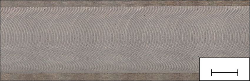
Metals 2021, 11, 660                                                                                              2 of 17

                       2. State of the Art
                       2.1. Friction Press Joining
                             Friction press joining is a novel joining process for the direct bonding of plastic compo-
                       nents and metals, as studied by Wirth et al. [9]. Direct joining (or direct bonding) is defined as
                       joining two parts without using additional material (e.g., adhesives, rivets or screws).
                             According to Meyer et al. [8], the process of FPJ is divided into five steps, analogously
                       to friction stir welding (FSW). The first step—the surface pretreatment—is an upstream
                       process that significantly influences the bond strength between the joining partners [8].
                       The actual joining process consists of a sequence of four individual actions (see Figure 1):

                       0. Surface modification: In this preliminary process step, the joining zone of the metallic
                             joining partner is pretreated to increase the cohesive forces in the bond.
                       1. Touch-down: In the first phase of the joining process, a cylindrical tool rotates (rotational
                             speed n) around its longitudinal axis. By applying an axial force Fa , the tool presses
                             onto the metallic surface in the negative z-direction. This plunging phase ends when
                             the tool has reached a certain z-position, or a specified axial force is applied.
                       2. Dwelling: The tool remains at the plunge spot for a defined time tV . This dwelling
                            causes a heating and subsequent deformation of the material, resulting in the release
                            of dissipative energy and a further heating of the process zone.
                       3. Joining: The tool is guided with a constant feed rate v along the metallic joining part-
                             ner’s surface. The plastic melts in the joining zone, which results in a bonding to the
                             pretreated joining surface (after cooling). (Previous publications referred to Phase
                             3 as welding. In this paper, we use the term joining and explain the reasons for this
                             rephrasing in Section 6.)
                       4. Retreat: The joining process ends with the retraction of the tool in the positive z-
                             direction.

                                            n

                                                Tool
                                1

                                                          3
                                                              v                         4

                                2

                       z
                           y
                                 x

                       Figure 1. Process sequence of FPJ (blue, thermoplastic material; gray, aluminum), according to
                       Meyer et al. [8].

                            The principle of direct joining with FSW-like processes is also known as Friction
                       Lap Welding (FLW). However, FLW is usually not associated with surface pretreatment
                       of the metallic joining partner [10]. Hence, in most studies, only polar plastics, such
                       as polyamides, were employed. In addition to non-reinforced plastics, numerous fiber-
                       reinforced (short and continuous fibers) plastics were joined via FLW and FPJ [11–13].
                       In most cases, various aluminum alloys were used as the metallic joining partner [11].
                       Notwithstanding, studies on the joining of copper specimens have also been reported [13].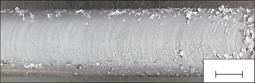
Metals 2021, 11, 660                                                                                             3 of 17

                       2.2. Adhesive Bonding
                             The adhesive bonding of plastic and metal components is challenging due to many
                       influences during the process, such as the air humidity, the curing time and the curing
                       temperature, which all impact the resulting bond properties [14]. Nonetheless, adhesive
                       bonding has become a standard procedure in the aircraft manufacturing industry to form
                       joints in the body and the wing structures [2].
                             According to Arenas et al. [15], two main adhesive systems are used in the aircraft
                       design for plastic-to-metal bonding: epoxy-based adhesives for high-strength static loads
                       and polyurethane-based adhesives for dynamically stressed joints. These adhesive systems
                       are characterized by their inherent properties, such as the rigidity (epoxy-based) or the flex-
                       ibility (polyurethane-based). Regardless of the adhesive system used, surface pretreatment
                       of the joining partners is a decisive factor that significantly influences the strength [16].
                             Furthermore, adhesive bonding is a standardized manufacturing process with a high
                       technology readiness level (TRL) [2]. However, this process requires a high level of process
                       control to minimize the environmental impact on the adhesive joint and quality control to
                       ensure the bond strength.

                       2.3. Technology Readiness Level and Technology Potential
                            The technology readiness level method is a procedure to assess a technology’s maturity
                       and promote its further development [17]. This assessment provides the basis for an
                       effective technology and innovation management for the industrial sector [18]. According
                       to Mankins [17], the classification mainly used in aviation is divided into nine individual
                       levels. The first two stages comprise the assessment of theoretical knowledge about a
                       technology. TRL 3–5 consider the technical implementation from the proof of concept
                       to the implementation in an industrial production environment. TRL 6 and 7 refer to
                       the production of a prototype. TRL 8 and 9 apply to the implementation in an actual
                       flight system. With the help of this very detailed classification, a categorization of novel
                       manufacturing methods according to their operational readiness is possible. It should be
                       noted that the transitions between the individual stages can be fuzzy.
                            Brousseau et al. [19] reduced this nine-step classification to a seven-step technology
                       maturity assessment (TMA) model:

                       Level 1 Basic technology research
                       Level 2 Feasibility study
                       Level 3 Technology development
                       Level 4 Technology demonstration
                       Level 5 System development/integration
                       Level 6 Integration in a production environment and validation
                       Level 7 Mass production/serial production

                            A technology profile developed using this method is valid for an individual company
                       and provides a far-reaching overview of the entire technology itself [19].
                            Reinhart and Schindler [20] used the TRL approach of Mankins [17], the TMA model
                       of Brousseau et al. [19] and the technological life cycle concept of Ford et al. [21] to develop
                       a technology profile. This profile combines these methods and accounts for uncertainties of
                       the given information. It was possible to quantify the linguistic criteria by using fuzzy logic,
                       resulting in a seven-step technology profile to describe the overall technological maturity.
                            Based on these findings, Hofer et al. [22] examined the potential of novel production
                       processes, such as the production of lithium-ion batteries and their impact on company
                       policy. The approach was extended to include the technical aspects and the economic
                       and strategic perspectives. According to Hofer et al. [22], these three elements form the
                       technology potential, which can be used to evaluate a novel technology and estimate the
                       possible benefits.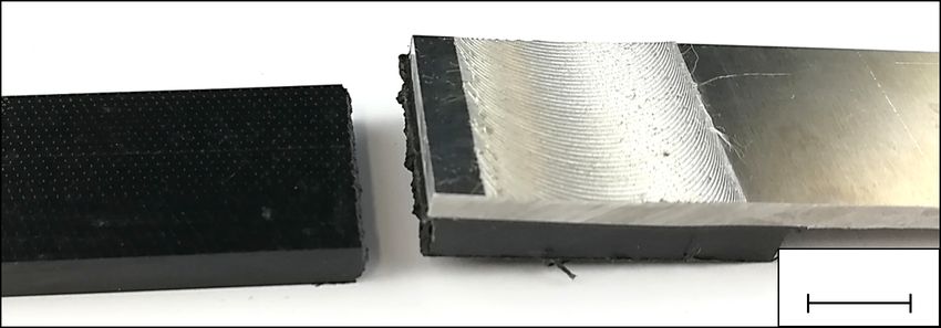
Metals 2021, 11, 660                                                                                                    4 of 17

                       3. Experimental Material and Set-Up
                       3.1. Experimental Material
                            To cover a broad spectrum of possible material combinations (MC), the experiments,
                       which led to the findings of this paper, were conducted using three different types of
                       plastic material in combination with two types of aluminum alloys (see Table 1). For a
                       better overview, the material combinations analyzed in this paper are indicated by Roman
                       numerals I–III in Table 1.

                       Table 1. Overview of the material combinations and the abbreviations used in this paper.

                                       Material Combination                                              Abbreviation
                       EN AW-6082-T6                                PE-HD                                          I
                       EN AW-6082-T6                               PA6-GF30                                        II
                       EN AW-2024-T3                                PPS-CF                                        III

                             Three semi-crystalline thermoplastics were chosen. The non-reinforced polyethy-
                       lene (PE-HD) is a typical example of mass plastics. In contrast, the short fiber-reinforced
                       polyamide (PA6-GF30) is an engineering plastic. As a variant of high-performance plas-
                       tics, the endless fiber-reinforced polyphenylene sulfide (PPS-CF), often used in aircraft
                       design [23], was chosen. This selection covers a wide range of mechanical and thermal
                       properties, which are listed in Appendix A (see Table A2). All samples were purchased as
                       sheet material from the corresponding suppliers.
                             The high-density polyethylene (PE-HD) distributed by S-Polytec GmbH, Germany,
                       Goch has a low density, high crystallinity, non-polar character and excellent chemical
                       resistance. Besides that, this group of plastics absorbs a minimal amount of water [24]. For
                       these reasons, these polymers are used in many applications, e.g., as micro-granules for
                       additive manufacturing [25] and implants [26]. The thickness of the material was 5 mm.
                             The second plastic used was a polyamide 6 with 30 % glass fiber content (PA6-GF30),
                       supplied by Ensinger GmbH, Germany, Nufringen, under the trade name TECAMID 6
                       GF30 black [27]. This group of plastics is known for its polar nature and high strength.
                       Therefore, it is the subject of various research projects in joining technology [28]. The
                       thickness of the material was 5 mm.
                             The endless carbon-fiber-reinforced (43 wt%) polyphenylene sulfide (PPS-CF) used
                       is a semi-crystalline high-performance thermoplastic sold by TenCate Advanced Com-
                       posites B.V., The Netherlands, Nijverdal, under the brand name CFK Cetex TC1100. The
                       fibers in the laminate are arranged in a 5H-satin configuration and laid in seven layers
                       [(0/90), (±45)]3 (0/90). High heat resistance, high chemical resistance and high stiffness
                       characterize this fiber-matrix composite. Hence, it has been widely used in aerospace
                       applications [23,29] and research [30]. The material thickness is derived from the above-
                       mentioned layer structure and was 2.17 mm [31].
                             The main aluminum alloy under study was an EN AW-6082-T6 [32], as used in several
                       publications on friction press joining [8,9,33]. The thickness was 3 mm.
                             The second aluminum alloy, a hardenable, high-strength EN AW-2024-T3 [34], is
                       frequently employed in aircraft manufacturing [35]. Due to its poor welding properties
                       and low corrosion resistance, this alloy is usually adhesively bonded. The sheet thickness
                       was 2 mm.

                       3.2. Surface Pretreatment
                            To compare the two technologies (FPJ and adhesive bonding), three different plastic–
                       metal combinations were joined. For both processes, the surface pretreatment is a significant
                       influencing factor affecting the resulting bond strength [8,16]. According to Wirth et al. [9],
                       laser-based surface pretreatment is advantageous compared to other methods, because of the
                       absence of chemicals as well as the fast and contact-free processing. For these reasons, the
                       surfaces of the metallic joining partners were modified by laser radiation. Based on Meyer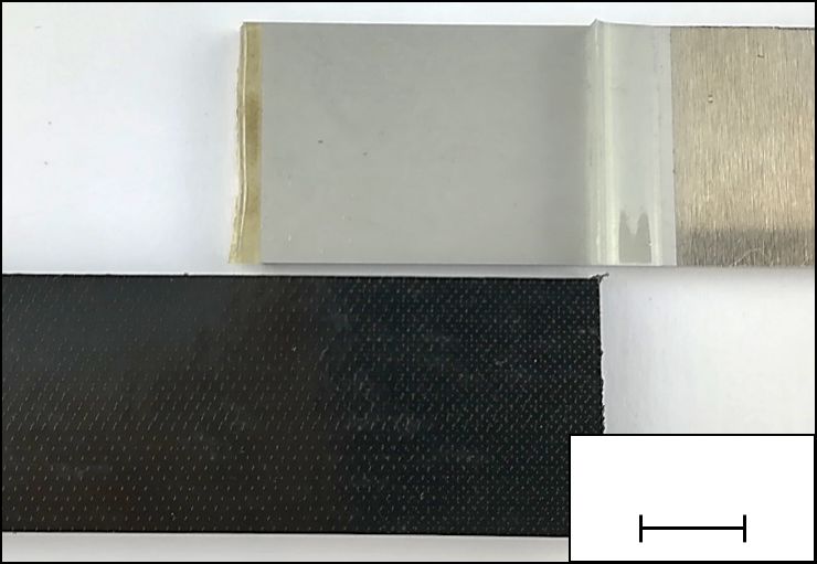
Metals 2021, 11, 660                                                                                                  5 of 17

                       et al. [8], a quasi-chaotic nanostructure was produced (see Figure 2) on both aluminum alloys.
                       This structure exhibits a highly porous oxide layer as well as directional independence. It
                       was generated using a pulsed laser system (Rofin-Sinar PowerlineF20) with a wavelength of
                       1064 nm (see Table 2). Compared with Lambiase [36], we used a different laser system for
                       surface pretreatment, which differs mainly in the pulse duration. In [36], small cutting edges
                       were created, while the surface modification used here utilizes the oxide layer that is formed.
                       A major advantage of this method is the fact that a considerably faster process is obtained
                       with two exposures, while [36] required 20 exposures.

                       Table 2. Laser structuring parameters for the generation of a quasi-chaotic nanostructure.

                       Parameter                                              Unit                                   Value
                       Power P                                                 W                                        20
                       Frequency f                                            kHz                                       20
                       Exposures n                                             –                                         2
                       Pulse spacing ps                                       µm                                        25
                       Focus diameter d f oc                                  µm                                        50
                       Pulse energy EP                                         mJ                                        1

                                  ps

                        ps

                                                                              10 µm                                 10 µm

                                       (a)                             (b)                                (c)

                       Figure 2. Illustration of the pulse pattern for a chaotic nanostructure (a) and scanning electron
                       microscope (SEM) images (acceleration voltage of 1 kV) of the generated structures on EN AW-2024-
                       T3 (b) and EN AW-6082-T6 (c).

                           The surface of the plastics was cleaned with ethanol to remove any grease and other
                       contamination. The surface was not pre-treated mechanically or physically.

                       3.3. Selection of the Adhesives and Bonding
                            For the adhesive joining of the three material combinations, different adhesive sys-
                       tems were used to obtain the maximum strength (see Table 3). The selection of the adhe-
                       sives is based on a literature review and consultation with the respective manufacturers.
                       The investigated adhesives are used either in this way or in a similar configuration, in
                       industrial applications.

                       Table 3. Overview of the material combinations, the used adhesive (A) and their abbreviation used
                       in this paper.

                       MC                         Adhesive                      Category                   Abbreviation
                        I                    Scotch Weld DP 8005              Acrylic-based                      I-A
                                                DELO 02 rapid                  Epoxy resin                      II-Aa
                        II
                                                DELO AD 948                   Polyurethane                      II-Ab
                       III                     Loctite EA 9466                 Epoxy resin                      III-A

                            A two-component acrylic-based adhesive system [37] was utilized for the material
                       combination of PE-HD and aluminum. Oguma and Naito [38] used an acrylic-based
                       Scotch-Weld DP8005 supplied by 3M to join glass fiber-reinforced polypropylene samples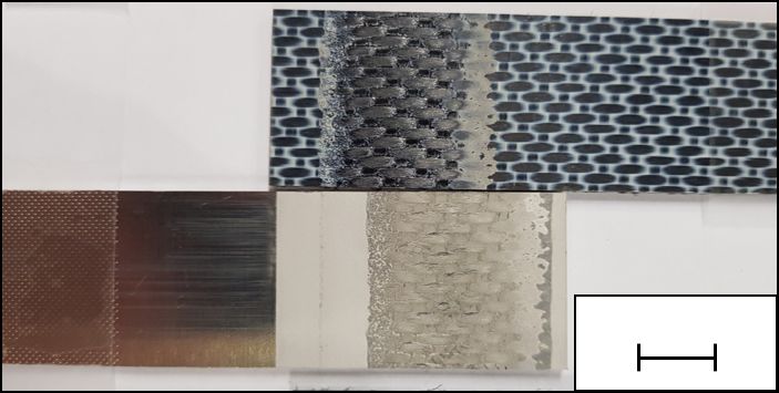
Metals 2021, 11, 660 6 of 17
to each other. As polyethylene is very similar to polypropylene (in terms of its chemical
structure), this adhesive system was selected.
To bond the polar polymer PA6-GF30, two different adhesive systems were used
according to Arenas et al. [15]: a two-component epoxy-based system (DELO 02 rapid) [39]
and a two-component polyurethane-based adhesive (DELO AD 948) [40].
For the high-strength bonds of PPS-CF and EN AW-2024-T3, the two-component
epoxy-based adhesive Loctite EA 9466 [41] from the Henkel AG was chosen, following
Spaggiari and Dragoni [42] and Soykok [43].
To ensure reproducibility, all adhesive bonds were executed twice. For a better
overview, the adhesive systems are designated in the following with the proposed material
combination (I–III), a hyphen and an A for adhesive. For Combination II, there is both an
epoxy-based (Aa) and a polyurethane-based (Ab) adhesive system (see Table 3).
The layer thickness of the adhesives was set to approximately 250 µm. For bonding
with II-Aa only, a layer thickness of approximately 100 µm was selected. The curing was
performed at room temperature (approximately 23 °C) for 120 h.
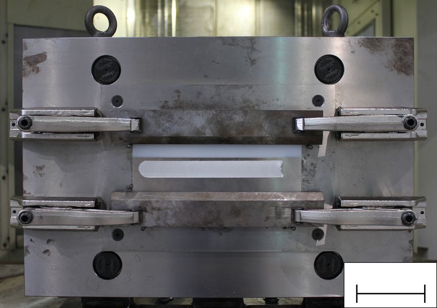
3.4. FPJ System, Clamping and Parameters
The FPJ experiments were conducted on a Heller MCH 250 CNC milling machine
(Workspace of 800 mm × 800 mm × 800 mm). The main spindle is positioned horizontally
on this machine and can be moved in the x- and the y-direction. The tilt angle α between
the tool and the workpiece can be adjusted by rotating the clamping base around the b-axis.
This clamping base can be moved in the z-direction and provides a maximum force of
30 kN with a positioning accuracy of 0.001 mm. The FPJ specimens were mounted on the
clamping base using a customized clamping system made of C45 steel with a base thickness
of 35 mm (see Figure 3). The tool used was made of XCrMoV5, had a diameter of 25 mm
and a flat front face. The process was conducted by using the force control presented
in [11].
Clamping
Polyethylene
Aluminum Friction track
b
y
x
z 100 mm
Figure 3. Customized clamping system for joining aluminum and thermoplastic material (in this
case polyethylene) by friction press joining [11].
The parameters used for the FPJ experiments were based on previous investigations [8,9]
and are listed in Table 4. For a better overview, roman numerals combined with a PS (I-PS–
III-PS) indicate the parameter sets (PS) for joining the different material combinations (see
Table 4). Each parameter set was conducted twice.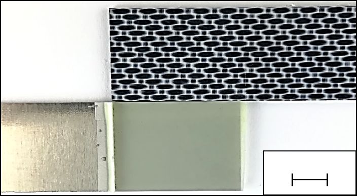
Metals 2021, 11, 660                                                                                            7 of 17

                       Table 4. Parameter sets for the FPJ experiments for each material combination and their used
                       abbreviation (abbr.); all experiments were conducted with a tilt angle α of 2°.

                       MC     Rot. Speed n in min−1       Feed Rate v in mm min−1       Ax. Force Fa in N     Abbr.
                                         400                         150                       2000            I-PSa
                                         600                         600                       2000            I-PSb
                        I                800                         450                       2000            I-PSc
                                         800                         600                       2000            I-PSd
                                        1000                         750                       2000            I-PSe
                                        600                          400                       2000           II-PSa
                                        600                          560                       2000           II-PSb
                        II
                                        800                          240                       2000           II-PSc
                                        800                          600                       2000           II-PSd
                                        1500                         450                       2500           III-PSa
                       III              2000                         300                       2500           III-PSb
                                        2500                         300                       2500           III-PSc

                       3.5. Test Geometry and Tensile Shear Tests
                            For both the bonding process and the FPJ process, the same sample dimensions
                       were used for each material combination (I–III). In each case, two plates measuring
                       100 mm × 250 mm were joined with an overlap of 35 mm. For the FPJ-experiments, the
                       seam length was 200 mm, while the adhesive samples’ bonding was over the entire contact
                       surface. Five 25 mm-wide tensile shear specimens were prepared out of the middle of
                       the joined plates, resulting in a total overlap of 875 mm2 for a single test sample. These
                       specimens were used for the tensile lap shear test on a material testing machine Z050
                       (Zwick/Roell, Germany, Ulm). The initial length l0 for this test was 115 mm. The tra-
                       verse speed was set to 50 mm min−1 for the combination of PE-HD and aluminum and
                       5 mm min−1 for the other material combinations.

                       4. Results and Discussion of the Experiments
                       4.1. Comparison of the Bond Strengths
                             The strength of the composites produced by FPJ were similar or higher than the
                       strength of the reference samples joined by adhesives (see Figure 4). For a better overview,
                       only the results of the best FPJ parameter set for the corresponding material combination
                       are shown in Figure 4. The results of all individual experiments are supplied in the
                       Appendix A in Tables A3 and A4.
                             For the material combination PE-HD and EN AW-6082-T6 (I), the composites produced
                       with FPJ showed the same tensile shear strength as the adhesive composites. Here, the
                       total adhesive forces exceeded the internal strength of the plastic joining partner. Therefore,
                       the maximum strength did not lead to the joint’s breakage but led to the elongation of
                       the plastic and its material hardening due to the alignment of the macromolecules (strain
                       hardening) (see Figure 5). The shown tensile shear strengths of approximately 2700 N thus
                       refer to the stress area (cross-section of plastic joining partner) of 125 mm2 . The measured
                       stress value of 21.6 MPa correlates well with the value of 23 MPa given in the datasheet
                       (see Table A2). To be able to investigate the joint strength more closely, the overlap length
                       should be reduced in further investigations in order to obtain a fracture in the joining zone.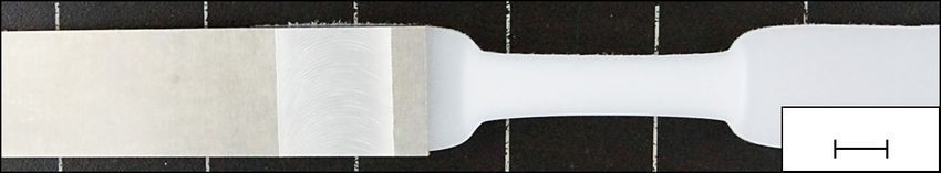
Metals 2021, 11, 660                                                                                                  8 of 17

                       Figure 4. Tensile shear strengths of selected joints (blue, FPJ; orange, adhesive bond) including the
                       standard deviation of five tensile shear specimens.

                                                                                    10 mm

                       Figure 5. Typical FPJ tensile shear test specimen made of PE-HD and EN AW-6082-T6 (I-PSd) after a
                       successful lap shear test with distinct strain hardened area.

                            The FPJ bonds for the material combination of PA6-GF30 and EN AW-6082-T6 (II)
                       showed a significantly higher bond strength than the reference samples (adhesive bonding)
                       (see Figure 4). In all cases, the plastic joining partner broke at the edge of the metallic
                       joining partner (see Figure 6). Concerning the stress cross-section (cross-section of the
                       plastic joining partner), the strength is 54.4 MPa, approximately 55 % of the value specified
                       on the datasheet. This reduced maximum tensile strength of the plastic joining partner
                       can be explained by a certain notch effect at the transition between the plastic and the
                       metal (see Figure 6a). As the end of the metal sheet is pressed into the plastic, the real
                       cross-sectional area is reduced and a sharp-edged transition is created. Another possible
                       explanation could be the thermal degradation of the plastic, which would also weaken
                       the bond strength. For the adhesive bond, a purely adhesive break between the plastic
                       and the adhesive film occurred. This fracture pattern showed that the bond between the
                       pretreated metal and the adhesive is high. In contrast, the bond between the adhesive and
                       the plastic is weak. Since the plastic surface was not pretreated except for a surface cleaning
                       (ethanol), no mechanical adhesion (form closure) could develop. Based on the results of
                       Don R. [44], it is assumed that due to the molecular structure of the polymer chains of the
                       plastic, neither the epoxy-based nor the polyurethane-based adhesive can form chemical
                       bonds (missing the reactive end groups) with the plastic. For this reason, the authors see
                       an advantage in the FPJ process for the material combination of polyamide and aluminum.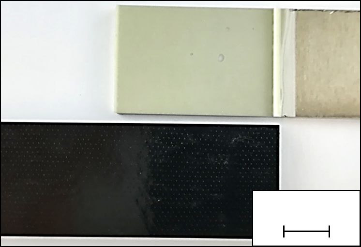
Metals 2021, 11, 660                                                                                                 9 of 17

                           Notch effect

                                                                10 mm

                                              (a)

                                            10 mm                                  10 mm

                                    (b)                                    (c)

                       Figure 6. Comparison of the surfaces at fracture of PA6-GF30 and EN AW-6082-T6 joined with: FPJ
                       (II-PSa) (a); epoxy-based adhesive (b); and polyurethane-based adhesive (c).

                            The strengths of the combination PPS-CF and EN AW-2024-T3 (III) also demonstrate
                       the benefit of FPJ. The fracture pattern of the FPJ bonds showed that the bond between the
                       plastic and the metal was high (plastic remains on the metal surface) and the bond between
                       the plastic and the fibers was the weak point (see Figure 7a). Moreover, not the entire
                       joining surface was heated and thus bonded (see Figure 7a). As a result, the fracture pattern
                       can be separated into an area where the PPS was not melted, an area where the bond
                       failed cohesively, and an area where the bond failed adhesively. Since joining the entire
                       surface was not possible, the actual stress in the bond was significantly higher. Therefore,
                       the potential of the FPJ process was not fully exploited. To counteract this effect, the heat
                       input into the bond should be improved further to plasticize the entire joining surface and
                       increase its strength. In contrast, joints produced by adhesion bonding show a distinctive
                       adhesive fracture between the epoxy-based adhesive and the plastic. Similar to material
                       combination II, the bond between the plastic and the adhesive was a weak point in the
                       composite. Therefore, FPJ is considered to be an advantageous process to join the material
                       combination III.

                        Not melted/
                        Not bonded

                           Fiber residues
                                                          10 mm                                                 10 mm

                                            (a)                                                   (b)

                       Figure 7. Comparison of the 25 mm wide samples after the tensile test: (a) joined with parameter set
                       III-PSa; and (b) joined with an epoxy-based adhesive.

                            In summary, the FPJ joints display an equivalent or even higher mechanical strength
                       compared to adhesive bonding. To characterize the actual bond, the overlap length should
                       be reduced in future studies, at least for the material combination of PE-HD or PA6-GF30
                       with EN AW-6082-T6, to achieve a fracture in the joining surface in the tensile tests. Only a
                       qualitative result could be derived from the tests presented within this study.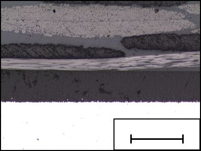
Metals 2021, 11, 660 10 of 17
4.2. Comparison of the Cross-Sections
After analyzing the tensile shear strengths and fracture surfaces, the cross-sections of
Version March 31, 2021 submitted to Metals 10 of 18
the individual samples were compared (see Figure 8).
PE-HD – EN AW-6082-T6 PA6-GF30 – EN AW-6082-T6 PPS-CF – EN AW-2024-T3
PE PA PPS
Al 500 µm Al 500 µm Al 500 µm
(a) FPJ: I-PSd (b) FPJ: II-PSa (c) FPJ: III-PSa
PE PA PA PPS
Ad. Ad. Ad. Ad.
Al 500 µm Al 500 µm Al 500 µm Al 500 µm
(d) Adhesive: I-A (e) Adhesive: II-Aa (f) Adhesive: II-Ab (g) Adhesive: III-A
Figure 8. Cross-sections of the joining zones for the three considered material combinations and the
Figure 8. Cross-sections of the joining zones for the three considered material combinations and the
two joining processes; the captions of the individual images refer to the process parameters used
two joining processes; the captions of the individual images refer to the process parameters used or the
or theapplied
applied adhesive.
adhesive. To achieve
To achieve a betteravisibility
better visibility of the
of the layered layered
structure, the structure, themicroscopic
contrast of the contrast of the
microscopic images
images was was increased,
increased, which
which causes a sidecauses
effect: athe
side effect: the
aluminum aluminum
appears black (8aappears black
and 8d) or (a,d) or
white.
white.The
The adhesive
adhesive layer
layer is indicated
is indicated as Ad. as Ad.
259 For
of the the Generally,
metal. FPJ bonds byshows,
melting it can
the be seen,
plastic, it canthat thewith
interact plastic interacts aluminum
the pretreated directly with the
surface
260 pretreated surface of the
and form high-strength aluminum. For the connection with PPS-CF (see Figure 8c), it can
bonds.
261 be seenForthat, due tojoints
all adhesive the low
(see matrix
Fig. 8d –content, the fibers
8g), a layered (light
structure gray) of
consisting partially
aluminum touch
(Al.),the metal
adhesive
262 (see red
(Ad.), circle).
and plasticThis effect
(PE, PA, can also
or PPS) be observed
was identified. The on the fracture
adhesive surface
penetrates of the tensile
the pretreated aluminumtests
263 surface
(see and thus
Figure forms a fiber
7a), where mechanical
remains interlock.
on theA surface
sharp separation between
of the metal. the plasticsby
Generally, PA6-GF30
meltingand the
264 PPS-CFitand
plastic, canthe corresponding
interact with theadhesives
pretreatedis visible.
aluminumThis separation indicates
surface and formthat the plastic was
high-strength not
bonds.
265 chemically
For allaffected,
adhesive andjoints
only weak
(see physical bonds exist.
Figure 8d–g), However,
a layered for the plastic
structure PE-HD
consisting of(see Fig. 8d),
aluminum
a small intermediate layer is visible. Here it appears that a reaction has taken place between the plastic
266
(Al.), adhesive (Ad.) and plastic (PE, PA or PPS) was identified. The adhesive penetrates the
267 and the adhesive (acrylic-based). The analysis of the fracture patterns confirms these observations. The
pretreated aluminum surface and thus forms a mechanical interlock. A sharp separation
268 adhesive bonds between thermoplastics and metals only occur when the plastic is chemically treated.
between the plastics PA6-GF30 and PPS-CF and the corresponding adhesives is visible. This
269 separation
4.3. Comparisonindicates that the
of the surface plastic was not chemically affected, and only weak physical
quality
bonds exist. However, for the plastic PE-HD (see Figure 8d), a small intermediate layer
270 During FPJ, the tool is guided along the surface of the metallic joining partner (see Fig. 1). This
is visible. Here, it appears that a reaction has taken place between the plastic and the
271 processing leads to a so-called friction track on the surface (similar to an FSW seam) (see Fig. 9). The
272
adhesive
term seam(acrylic-based).
is avoided here since Thethe
analysis of the
actual seam fracture
is located at patterns confirms
the interface betweenthese observations.
the metal sheet and
273
The adhesive bonds between thermoplastics and metals only occur
the plastic component. This distinctive feature determines the visual appearance of the bond. when the plastic is
274
chemically treated.
In general, the alloy EN AW 2024-T3 showed superficial flaking with a small aluminum layer
275 peeled off (see Fig. 9a). As a result, the characteristic arc texture formation is not distinct. This behavior
276
4.3. Comparison
is not of theInSurface
yet understood. order toQuality
exclude an influence of the process parameters, additional tests with
277 During
similar FPJ,and
feed rates therotational
tool is guided
speeds werealong the surface
performed. of thesuperficial
A reduced metallic flaking
joiningformation
partner was(see
278 Figure
observed1).for
This processing
the alloy EN AW leads
2024-T3.to For
a so-called
this reason,friction
it can betrack on the
assumed thatsurface (similar
the material to an
has a more
279 significant
FSW seam)influence
(see Figureon the
9). quality
The term of the friction
seam surface,here
is avoided although
since the
theprocess
actual parameters permitat
seam is located
280 a certain adjustment of its quality. In contrast, no delamination could be detected
the interface between the metal sheet and the plastic component. This distinctive feature for the alloy EN
281 AW-6082-T6 (see Fig. 9b). Other surface
determines the visual appearance of the bond. defects known from FSW [45], such as surface galling, were
282 only observed sporadically. However, since the friction track is a characteristic optical feature, this
283 aspect should be considered more closely for industrialization purposes.Metals 2021, 11, 660 11 of 17
10 mm 10 mm
(a) (b)
Figure 9. Comparison of the friction tracks (25 mm in width) between the aluminum alloy EN AW-
2024-T3 (a) processed with parameter set III-PSb and EN AW-6082-T6 (b) produced with parameter
set II-PSa.
In general, the alloy EN AW 2024-T3 showed superficial flaking with a small aluminum
layer peeled off (see Figure 9a). As a result, the characteristic arc texture formation is not
distinct. This behavior is not yet understood. To exclude an influence of the process
parameters, additional tests with similar feed rates and rotational speeds were performed.
A reduced superficial flaking formation was observed for the alloy EN AW 2024-T3. For
this reason, it can be assumed that the material has a more significant influence on the
quality of the friction surface, although the process parameters permit a certain adjustment
of its quality. In contrast, no delamination could be detected for the alloy EN AW-6082-T6
(see Figure 9b). Other surface defects known from FSW [45], such as surface galling, were
only observed sporadically. However, since the friction track is a characteristic optical
feature, this aspect should be considered more closely for industrialization purposes.
5. Technical Maturity
5.1. Technology Readiness Level of FPJ
As outlined in the Introduction, the technological maturity is a crucial aspect for the
industrialization of a technology. To be able to compare the technological and economic
aspects, it is essential to evaluate the maturity of a new technology. Therefore, the TRL of
FPJ is discussed hereafter.
To assess the technological maturity of FPJ, the state of the art was evaluated. Further-
more, 15 experts on FPJ, FLW and FSW discussed this topic in two meetings, according
to the method of Reinhart and Schindler [20] (as the evaluation forms published in [20],
which serve as a basis for the assessment, are too extensive to be included in this paper,
please feel free to ask the author for the data). As described in Section 2.3, the maturity
model comprises seven levels, representing different stages of a technology’s evolution.
The technology readiness, according to the maturity levels for the analyzed joining process
(FPJ), is shown in Figure 10. The diagram is structured according to the phases (vertical)
and the maturity levels (horizontal). The error bars show the uncertainty contained in the
answers of the experts.
Levels 1 and 2 (b asics) indicate an advanced state of progress. Thus, the theoretical
background on FPJ is well known, and the correlation between the individual process
parameters is generally understood. This status is also confirmed by the numerous publica-
tions regarding FPJ or FLW (see Section 2).
Levels 3 and 4 represent a high degree of progress. This advanced stage illustrates
that the development and the validation of the technology are well advanced. Furthermore,
prototype components have already been produced. Therefore, the development of the
technology and the validation on a laboratory scale can be classified as sufficiently ad-
vanced. Up to now, only plane surfaces (sheets) have been joined. However, the geometry
flexibility is considered to be similar to FSW, thus it can be assumed that curved surfaces
can also be joined ([46] pp. 131–133).
The integration into an operating resource, assessed for Level 5, can also be classified
as sufficient, partly because the FPJ process relies on similar resources to the FSW process.
In the further qualification of the technology for series production in Level 6 (production
structure) and optimization in the series production (Level 7), a clear decline in the degree
of progress can be seen. The high standard deviation for Level 6 indicates high uncertaintiesMetals 2021, 11, 660 12 of 17
in identifying the characteristics in the production environment. The low progress value
indicates that the technology is still hardly established in industrial production, but it
is increasingly perceived as an alternative to other joining processes. It should be noted
that up to now there are no publications concerning lifetime/fatigue tests of the FPJ/FLW
bonds, nor studies dealing with the mechanical properties at increased or low temperatures
(−60 to 60 ◦ C).
To calculate the overall maturity of the technology and to indicate uncertainties in
the evaluation, a Monte Carlo simulation with 1000 runs was conducted. A more detailed
description of the method used is given in Reinhart and Schindler [20]. With an average
value of around 61± 6%, an advanced development stage of the FPJ technology was
identified. This result shows that this novel technology is already well advanced and on
the verge of entering the industrial production environment.
Level 7 Optimization
Level 6 Qualification
Level 5
Level 4
Development
Level 3
Level 2
Basics
Level 1
0% 20 % 40 % 60 % 80 % 100 %
State of progress
Figure 10. Level of maturity according to the individual development stages, based on the method
of Reinhart and Schindler [20].
5.2. Technology Potential of FPJ
To evaluate the technology potential, the economic and company-strategic aspects
should be considered in addition to the mentioned technical perspective. Consequently,
only the economic points are discussed hereafter since the authors are unable to cover
company-strategic approaches.
According to Hofer et al. [22], economic conditions include the cost-cutting potential,
the revenue-increase potential and the economic potential. These three topics with respect
to the technology covered by this paper are summarized shortly in the following. The
possibility of direct joining of plastic components and metals eliminates the need for
adhesives. The time saved due to the elimination of curing time must be weighed against
the joining time required for the FPJ. This time depends on the material as well as on
the geometry. In general, it can be assumed that a reduction of the production time
is possible, especially compared to epoxy-based adhesives (curing time of 24 h at room
temperature [39]). Due to the trend in aircraft design to replace thermosetting materials
with thermoplastic materials [29], there is also an increasing number of new scenarios for
applying friction press joining. The elimination of the adhesive, and thus the reduction of
the total mass, result in a significant cost advantage over the aircraft’s lifetime, which can
compensate for the higher cost of the system technology (CNC machine center, meteorology
and software) used for FPJ. The reduction of the total mass leads to a reduction in the fuel
consumption. In particular, the fuel economy is essential for new aircraft’s sales prices,
which is why an increase in the profit can be expected when using the FPJ technology.Metals 2021, 11, 660 13 of 17
These considerations indicate the high economic potential of FPJ for specific joining
processes. Together with the already existing high technological maturity, only minor risks
arise for the application of this technology in the industrial context.
6. Classification of the FPJ Process
Finally, after discussing the technological and economical aspects, this paragraph
deals with the classification and categorization of the FPJ process into the DIN 8580 [47]
standard. In the following section, a proposal is discussed to classify the process based on
the current knowledge in the literature (see Figure 11).
The objective of the classification is to promote the advancement of the joining process
based on the current data available rather than constraining it within a specific manufac-
turing processing. It is possible that the category of the process needs to be redefined or
new sub-categories need to be proposed to more accurately describe the process.
Standard Manufacturing
Possible standard for FPJ processes
Standard for FSW DIN 8580
Main group 4 Joining
DIN 8593-0
4.6 Joining 4.8 Adhesive
Group
by welding bonding
DIN 8593-6 DIN 8593-8
Subgroup 4.6.1 Pressure 4.6.2 Fusion 4.8.1 Adhesive bond-
welding welding ing with physically
curing adhesives
Item
4.6.1.6 Pressure 4.6.2.6 Fusion
welding by welding by
movement movement 4.8.1.3 Activa-
of mass of mass tion bonding
Figure 11. A recommendation for the classification of the friction press joining process according to
the DIN 8580 [47] standard for manufacturing processes.
Friction press joining is a manufacturing process for joining thermoplastic mate-
rials and metal sheets. Thus, it belongs to the fourth main group Joining, defined in
DIN 8593-0 [47,48]. The related process friction stir welding (FSW), from which FPJ was
derived, is standardized in DIN EN ISO 25239-1 [49] and assigned to Pressure welding (1st
subgroup) under DIN 8593-6 [50] (Joining by welding). Pressure welding is subdivided
further according to DIN 1910-100 [51], where the FSW process is classified in item 4.6.1.6
Pressure welding by movement of mass [50]. However, since one joining partner (the thermo-
plastic material) has to be melted during friction press joining, it is not classifiable as a
pressure welding process, according to DIN 8593-6 [50].
In the second subgroup, 4.6.2 Fusion welding (DIN 8593-6 [50]), item 4.6.2.6 Fusion
welding by movement of mass would be a possible alternative. Thus far, no processes are listed
under this item. An essential criterion for the classification in this item is the type of the
bond. According to Wirth et al. [9], FPJ is based on micro-form-closure, and according to
Meyer et al. [8] on micro-form-closure and Van der Waals forces. As these two phenomena
are based on cohesive forces, a classification in this category is conceivable. In addition,
Liu et al. [10,52] showed that Al-0-C bonds were formed at the aluminum/polyamide
interface. Here, the carbonyl group at the PA66 surface was essential for the formation
of this a bond mechanism. This type of formation proved to be a key factor to achieve aMetals 2021, 11, 660 14 of 17
high joint strength. It provided also an explanation why aluminum alloys can be directly
welded to PA66 plates with a high joint strength.
Based on the bonding mechanisms, a second possibility is a classification according to
DIN 8593-8 (Adhesive bonding) [53]. For FPJ, the plastic serves as a joining partner, as well
as an adhesive. During the process, the heat input is conducted externally through friction
into the metallic joining partner and through conduction into the joining zone, causing the
adhesive (plastic) to be melted. Therefore, this process can be seen as a hot-melt process,
which belongs to 4.8.1.3 Activation bonding.
In summary, an indexing to Fusion welding by movement of mass (item 4.6.2.6) and an
assignment to Activation bonding (item 4.8.1.3) is conceivable. Since FPJ can be seen as a
hot-melt process, the authors recommend classifying FPJ as Activation bonding. For this
reason, we use the term joining or bonding, instead of welding.
7. Summary, Conclusions and Outlook
In the context of this publication, a benchmark study was conducted on friction press
joining and adhesive bonding of plastic–metal composites. Different adhesive systems
were selected, and their resulting tensile strengths were compared to the strengths of the
friction-press-joined reference samples. It was found that the direct bonds showed higher
or at least equivalent tensile strengths compared to the samples joined with adhesives.
In addition to this technical aspect, the technological maturity and potential were
evaluated. The analyses revealed that the FPJ technology is well advanced and near of its
application in industry. Altogether, the following main conclusions can be formulated:
C1 The achieved maximum tensile shear strengths for the studied material combinations
joined by FPJ are higher than those of the comparative samples joined by adhesive
bonding.
C2 The overall technological maturity of friction press joining was rated as 61± 6%. Thus,
the technology is ready to be embedded in an industrial production environment.
C3 The technological potential to replace adhesive bonding in aircraft design can be
classified as high.
C4 A classification of the process (FPJ) according to DIN 8593-0 into Activation bonding
(item 4.8.1.3) is conceivable.
This benchmark study forms the basis for a validation in an actual production environ-
ment of mass products. Besides that, a detailed economic evaluation of the processes should
confirm the discussed cost-saving potential. An additional key aspect for future studies is
to investigate the long-term mechanical properties under the influence of temperature in
order to qualify the FPJ technology for aircraft.
Author Contributions: Conceptualization, S.P.M.; methodology, S.P.M.; validation, S.P.M. and
M.T.H.; formal analysis, S.P.M. and M.T.H.; investigation, S.P.M. and M.T.H.; resources, S.P.M.
and J.B.H.; data curation, S.P.M. and M.T.H.; writing—original draft preparation, S.P.M. and J.B.H.;
writing—review and editing, J.B.H. and M.F.Z.; visualization, S.P.M.; supervision, S.P.M.; project
administration, S.P.M.; and funding acquisition, S.P.M., J.B.H. and M.F.Z. All authors have read and
agreed to the published version of the manuscript.
Funding: This work was funded by the Deutsche Forschungsgemeinschaft (DFG, German Research
Foundation) (418104776).
German Research Foundation
Institutional Review Board Statement: Not applicable.Metals 2021, 11, 660 15 of 17
Informed Consent Statement: Not applicable.
Conflicts of Interest: The authors declare no conflict of interest.
Appendix A
The Appendix lists all tensile test experiments (see Tables A3 and A4) and the material
properties of the used components (see Tables A1 and A2).
Table A1. Selected thermal and mechanical properties of the aluminum EN AW-6082-T6 and EN
AW-2024-T3 [32,34,54].
EN AW
Property Unit 6082 2024
Condition – T6 T3
Tensile strength Rm N mm−2 300–350 435
Yield strength R p0.2 N mm−2 240–320 290
Elongation at fracture A50mm % 8–14 14
Young’s modulus E MPa 70,000 70,000
Density ρ g cm−3 2.70 2.77
Melting range Tm °C 585–650 505–640
Thermal conductivity λ W m−1 K−1 150–185 130–150
Coefficient of linear thermal expansion α 10−6 K−1 23.4 22.9
Table A2. Selected mechanical and thermal properties of the plastic components used [24,27,31].
Property Unit PE-HD PA6-GF30 PPS-CF
Tensile strength Rm N mm−2 23 98 752–785
Yield strength R p0.2 N mm−2 – 98 608
Elongation at fracture A % – 5 –
Young’s modulus E MPa 1100 5700 56,000–58,000
Density ρ g cm−3 0.96 1.36 1.55
Crystallization temperature (range) Tc °C 126–130 218 280
Thermal conductivity λ W m−1 K−1 0.38 0.41 –
Coefficient of linear thermal expansion α 10−4 K−1 1.8 0.6 –
Table A3. Lap shear test results for all FPJ joined specimens.
MC Abbr. Tensile Strength in N Standard Deviation σ in N
I-PSa 2576.3 173.85
I-PSb 2710.0 53.88
I I-PSc 2716.8 17.77
I-PSd 2742.2 24.67
I-PSe 2745.8 12.92
II-PSa 6844.4 67.51
II-PSb 6606.8 202.57
II
II-PSc 6199.4 194.48
II-PSd 6478.6 148.96
III-PSa 8613.6 308.01
III III-PSb 7289.2 530.86
III-PSc 7046.6 564.89Metals 2021, 11, 660 16 of 17
Table A4. Lap shear test results for all adhesively bonded specimens.
MC Abbr. Tensile Strength in N Standard Deviation σ in N
I I-A 2785.0 12.76
II-Aa 489.0 170.01
II
II-Ab 924.8 51.39
III III-A 2082 501.20
References
1. Marsh, G. Airbus A350 XWB update. Reinf. Plast. 2010, 54, 20–24. [CrossRef]
2. Higgins, A. Adhesive bonding of aircraft structures. Int. J. Adhes. Adhes. 2000, 20, 367–376. [CrossRef]
3. Hertle, S.; Kleffel, T.; Wörz, A.; Drummer, D. Production of polymer-metal hybrids using extrusion-based additive manufacturing
and electrochemically treated aluminum. Addit. Manuf. 2020, 33, 101135. [CrossRef]
4. Lucchetta, G.; Marinello, F.; Bariani, P.F. Aluminum sheet surface roughness correlation with adhesion in polymer metal hybrid
overmolding. CIRP Ann. 2011, 60, 559–562. [CrossRef]
5. Arai, S.; Sugawara, R.; Shimizu, M.; Inoue, J.; Horita, M.; Nagaoka, T.; Itabashi, M. Excellent bonding strength between steel and
thermoplastic resin using roughened electrodeposited Ni/CNT composite layer without adhesives. Mater. Lett. 2020, 263, 127241.
[CrossRef]
6. Balle, F.; Wagner, G.; Eifler, D. Ultrasonic Metal Welding of Aluminium Sheets to Carbon Fibre Reinforced Thermoplastic
Composites. Adv. Eng. Mater. 2009, 11, 35–39. [CrossRef]
7. Emrich, N.; Meyer, S.P.; Daub, R. Ageing behavior of thermally joined hybrids of laser pre-treated metal and thermoplastic
polymers. In Proceedings of the 35th International Conference of the Polymer Processing Society (Pps-35), Çeşme-Izmir, Turkey,
26–30 May 2019; AIP Publishing: New York, NY, USA, 2020; p. 020001. [CrossRef]
8. Meyer, S.P.; Wunderling, C.; Zaeh, M.F. Influence of the laser-based surface modification on the bond strength for friction press
joining of aluminum and polyethylene. Prod. Eng. 2019, 13, 721–730. [CrossRef]
9. Wirth, F.X.; Zaeh, M.F.; Krutzlinger, M.; Silvanus, J. Analysis of the Bonding Behavior and Joining Mechanism during Friction
Press Joining of Aluminum Alloys with Thermoplastics. Procedia CIRP 2014, 18, 215–220. [CrossRef]
10. Liu, F.C.; Liao, J.; Nakata, K. Joining of metal to plastic using friction lap welding. Mater. Des. 2014, 54, 236–244. [CrossRef]
11. Meyer, S.P.; Bernauer, C.J.; Grabmann, S.; Zaeh, M.F. Design, evaluation, and implementation of a model-predictive control
approach for a force control in friction stir welding processes. Prod. Eng. 2020, 54, 20. [CrossRef]
12. Nagatsuka, K.; Yoshida, S.; Tsuchiya, A.; Nakata, K. Direct joining of carbon-fiber–reinforced plastic to an aluminum alloy using
friction lap joining. Compos. Part B Eng. 2015, 73, 82–88. [CrossRef]
13. Wu, L.H.; Nagatsuka, K.; Nakata, K. Direct joining of oxygen-free copper and carbon-fiber-reinforced plastic by friction lap
joining. J. Mater. Sci. Technol. 2018, 34, 192–197. [CrossRef]
14. Custódio, J.; Broughton, J.; Cruz, H. A review of factors influencing the durability of structural bonded timber joints. Int. J. Adhes.
Adhes. 2009, 29, 173–185. [CrossRef]
15. Arenas, J.M.; Alía, C.; Narbón, J.J.; Oca na, R.; González, C. Considerations for the industrial application of structural adhesive
joints in the aluminium-composite material bonding. Compos. Part B Eng. 2013, 44, 417–423. [CrossRef]
16. Zimmermann, S.; Specht, U.; Spieß, L.; Romanus, H.; Krischok, S.; Himmerlich, M.; Ihde, J. Improved adhesion at titanium
surfaces via laser-induced surface oxidation and roughening. Mater. Sci. Eng. A 2012, 558, 755–760. [CrossRef]
17. Mankins, J.C. Technology Readiness Levels; A White Paper; Office of Space Access and Technology, NASA: Greenbelt, MD, USA, 1995.
18. Cetindamar, D.; Phaal, R.; Probert, D. Understanding technology management as a dynamic capability: A framework for
technology management activities. Technovation 2009, 29, 237–246. [CrossRef]
19. Brousseau, E.; Barton, R.; Dimov, S.; Bigot, S. A Methodology for Evaluating the Technological Maturity of Micro and Nano
Fabrication Processes. In Precision Assembly Technologies and Systems; Ratchev, S., Ed.; Springer: Berlin/Heidelberg, Germany,
2010; pp. 329–336.
20. Reinhart, G.; Schindler, S. A Strategic Evaluation Approach for Defining the Maturity of Manufacturing Technologies. Int. J. Ind.
Manuf. Eng. 2010, 4, 1291–1296.
21. Ford, D.; Ryan, C. Taking technology to market. Harv. Bus. Rev. 1981, 59, 117–126.
22. Hofer, A.; Schnell, J.; Beck, B.; Reinhart, G. Potential-based Technology Planning for Production Companies. Procedia CIRP 2019,
81, 1400–1405. [CrossRef]
23. Amancio-Filho, S.T.; dos Santos, J.F. Joining of polymers and polymer-metal hybrid structures: Recent developments and trends.
Polym. Eng. Sci. 2009, 49, 1461–1476. [CrossRef]
24. S-POLYTEC GmbH. Technical Data Sheet: PE-HD; S-POLYTEC GmbH: Goch, Germany, September 7, 2019.
25. Schäfer, C.; Meyer, S.P.; Osswald, T.A. A novel extrusion process for the production of polymer micropellets. Polym. Eng. Sci.
2018, 44, 1391. [CrossRef]Metals 2021, 11, 660 17 of 17
26. Kurth, M.; Eyerer, P.; Ascherl, R.; Dittel, K.; Holz, U. An evaluation of retrieved UHMWPE hip joint cups. J. Biomater. Appl. 1988,
3, 33–51. [CrossRef] [PubMed]
27. Ensinger Ltd. TECAMID 6 GF30 Black—Stock Shapes; Ensinger Ltd.: Nufringen, Germany, 2019.
28. Wolf, M.; Kleffel, T.; Leisen, C.; Drummer, D. Joining of Incompatible Polymer Combinations by Form Fit Using the Vibration
Welding Process. Int. J. Polym. Sci. 2017, 2017, 6809469 doi:10.1155/2017/6809469. [CrossRef]
29. Mathijsen, D. Leading the way in thermoplastic composites. Reinf. Plast. 2016, 60, 405–407. [CrossRef]
30. André, N.M.; Goushegir, S.M.; dos Santos, J.F.; Canto, L.B.; Amancio-Filho, S.T. Friction Spot Joining of aluminum alloy 2024-T3
and carbon-fiber-reinforced poly(phenylene sulfide) laminate with additional PPS film interlayer: Microstructure, mechanical
strength and failure mechanisms. Compos. Part B Eng. 2016, 94, 197–208. [CrossRef]
31. TenCate Advanced Composites BV. Data Sheet: Cetex TC1100 PPS; TenCate Advanced Composites BV: Morgan Hill, CA, USA,
2019. Available online: https://www.toraytac.com/media/221a4fcf-6a4d-49f3-837f-9d85c3c34f74/smphpw/TAC/Documents/
Data_sheets/Thermoplastic/UD%20tapes,%20prepregs%20and%20laminates/Toray-Cetex-TC1100_PPS_PDS.pdf (accessed
on 14 March 2021).
32. Gemmel Metalle & Co. GmbH. Technical Data Sheet: AlMgSi1 F30; Gemmel Metalle & Co. GmbH: Berlin, Germany, 2019.
33. Meyer, S.P.; Wunderling, C.; Zaeh, M.F. Friction press joining of dissimilar materials: A novel concept to improve the joint
strength. In Proceedings of the 22nd International ESAFORM Conference on Material Forming: ESAFORM 2019, Vitoria-Gasteiz,
Spain, 8–10 May 2019; AIP Publishing: New York, NY, USA, 2019; p. 050031. [CrossRef]
34. Batz + Burgel GmbH & Co. KG. Data Sheet: EN AW-2024; Batz + Burgel GmbH & Co. KG: Friedberg, Germany, 2019.
35. Kumar, B.; Widener, C.; Jahn, A.; Tweedy, B.; Cope, D.; Lee, R. Review of the Applicability of FSW Processing to Aircraft
Applications. In Proceedings of the 46th AIAA/ASME/ASCE/AHS/ASC Structures, Structural Dynamics and Materials
Conference, Austin, TX, USA, 18–21 April 2005; American Institute of Aeronautics and Astronautics: Reston, VA, USA, 2005;
p. 423. [CrossRef]
36. Lambiase, F.; Paoletti, A.; Grossi, V.; Di Ilio, A. Friction assisted joining of aluminum and PVC sheets. J. Manuf. Process. 2017, 29,
221–231. [CrossRef]
37. 3M. Technical Data Sheet: Scotch-Weld Structural Plastic Adhesive: DP-8005; 2020; Available online: https://www.bindingsource.
com/images/Customer-files/8005dsd.pdf (accessed on 14 March 2021).
38. Oguma, H.; Naito, K. Effect of stress ratio on the fatigue fracture mechanism of adhesive single-lap joints: In case of GF/PP
plates and an acrylic-based structural adhesive. Procedia Struct. Integr. 2019, 19, 224–230. [CrossRef]
39. DELO. Data Sheet: DELO 02 Rapid; 2020; Available online: https://www.delo.de/fileadmin/datasheet/DELO-DUOPOX_02%2
0rapid_%28TIDB-de%29.pdf (accessed on 14 March 2021).
40. DELO. Data Sheet: DELO-PUR AD948; 2020; Available online: https://substratec.com/de/download/1c1b1a18-66af-4eba-a4e6
-fb9c5869f0de/DELO-PUR_AD948_%28TIDB-D%29.pdf (accessed on 14 March 2021).
41. Henkel AG. Data Sheet: LOCTITE EA9466; 2020; Available online: http://tds.henkel.com/tds5/Studio/ShowPDF/EA%209466
-EN?pid=EA%209466&format=MTR&subformat=REAC&language=EN&plant=WERCS (accessed on 14 March 2021).
42. Spaggiari, A.; Dragoni, E. Effect of Mechanical Surface Treatment on the Static Strength of Adhesive Lap Joints. J. Adhes. 2013, 89,
677–696. [CrossRef]
43. Soykok, I.F. Degradation of single lap adhesively bonded composite joints due to hot water ageing. J. Adhes. 2017, 93, 357–374.
[CrossRef]
44. Don, R.C.; Gillespie, J., Jr.; McKnight, S. Bonding Techniques for High Performance Thermoplastic Compositions. U.S. Patent
5643390A, 1 July 1997.
45. Soni, N.; Chandrashekhar, S.; Kumar, A.; Chary, V. Defects Formation during Friction Stir Welding: A Review. Int. J. Eng. Manag.
Res. 2017, 7, 121–125.
46. Ruhstorfer, M. Friction Stir Welding of Tubes. Ph.D. Thesis, Technical University of Munich (TUM), Munich, Germany, 2012.
47. DIN 8580:2003-09, Manufacturing Processes—Terms and Definitions, Division; Beuth Verlag GmbH: Berlin, Cermany, 2003. [CrossRef]
48. DIN 8593-0:2003-09, Manufacturing Processes Joining—Part 0: General: Classification, Subdivision, Terms and Definitions; Beuth Verlag
GmbH: Berlin, Cermany, 2003. [CrossRef]
49. DIN EN ISO 25239-1:2019-06, Friction Stir Welding—Aluminium—Part 1: Vocabulary; Beuth Verlag GmbH: Berlin, Cermany, 2019.
[CrossRef]
50. DIN 8593-6:2003-09, Manufacturing Processes Joining—Part 6: Joining by Welding; Beuth Verlag GmbH: Berlin, Cermany, 2003.
[CrossRef]
51. DIN 1910-100:2008-02, Welding and Allied Processes—Vocabulary—Part 100: Metal Welding Processes with Additions to DIN EN
14610:2005; Beuth Verlag GmbH: Berlin, Cermany, 2008. [CrossRef]
52. Liu, F.C.; Dong, P.; Lu, W.; Sun, K. On formation of Al O C bonds at aluminum/polyamide joint interface. Appl. Surf. Sci. 2019,
466, 202–209. [CrossRef]
53. DIN 8593-8:2003-09, Manufacturing Processes Joining—Part 8: Joining by Means of Adhesives; Beuth Verlag GmbH: Berlin, Cermany,
2003. [CrossRef]
54. Otto Fuchs KG. Technical Information: Material Data Sheet Aluminium; Otto Fuchs KG: Meinerzhagen, Germany, 2019. Available
online: https://www.otto-fuchs.com/en/service/material-information.html (accessed on 14 March 2021).You can also read