A toolbox for neuromorphic sensing in robotics
←
→
Page content transcription
If your browser does not render page correctly, please read the page content below
A toolbox for neuromorphic sensing in robotics
                                                                                                   Julien Dupeyroux∗

                                           Abstract— The third generation of artificial intelligence (AI)           In contrast, neuromorphic systems are characterized by
                                        introduced by neuromorphic computing is revolutionizing the              the asynchronous and independent execution of the neurons
                                        way robots and autonomous systems can sense the world,                   within the neural net, therefore enabling more flexibility, as
                                        process the information, and interact with their environment.
                                        The promises of high flexibility, energy efficiency, and robust-         well as the ability to learn the timing information. In this
                                        ness of neuromorphic systems is widely supported by software             respect, spiking neural networks (SNNs) feature biologically
                                        tools for simulating spiking neural networks, and hardware               inspired neurons that fire independently and asynchronously
arXiv:2103.02751v1 [cs.RO] 3 Mar 2021

                                        integration (neuromorphic processors). Yet, while efforts have           of the others. So far, SNNs have been widely studied in
                                        been made on neuromorphic vision (event-based cameras), it               simulations, thanks to the booming efforts in designing
                                        is worth noting that most of the sensors available for robotics
                                        remain inherently incompatible with neuromorphic computing,              convenient simulation environments like the Python-based
                                        where information is encoded into spikes. To facilitate the use          APIs NORSE [1], Brian [2], Nengo [3], or PySNN1 . Un-
                                        of traditional sensors, we need to convert the output signals into       fortunately, the performances of SNNs remain limited for
                                        streams of spikes, i.e., a series of events (+1, −1) along with          robotic applications, the major reason being that SNNs are
                                        their corresponding timestamps. In this paper, we propose a              executed on conventional, synchronous hardware.
                                        review of the coding algorithms from a robotics perspective and
                                        further supported by a benchmark to assess their performance.               Over the past few years, intense efforts have been put in
                                        We also introduce a ROS (Robot Operating System) toolbox                 the design of neuromorphic hardware, such as HICANN [4],
                                        to encode and decode input signals coming from any type of               NeuroGrid [5], TrueNorth [6], SpiNNaker [7], Loihi [8],
                                        sensor available on a robot. This initiative is meant to stimulate       and SPOON [9]. Although these neuromorphic chips remain
                                        and facilitate robotic integration of neuromorphic AI, with the          under development, some of them are getting integrated
                                        opportunity to adapt traditional off-the-shelf sensors to spiking
                                        neural nets within one of the most powerful robotic tools, ROS.          onboard robots to push the frontiers of neuromorphic sensing
                                                                                                                 and control in robotics [10], [11], [12], [13]. Early results
                                                                                                                 show outstanding performances, such as extremely fast exe-
                                                               I. I NTRODUCTION                                  cution (up to several hundred kHz) along with high energy
                                                                                                                 efficiency. Yet, sensing may represent the ultimate bottleneck
                                           Neuromorphic artificial intelligence (AI) is the so-called            of neuromorphic AI in robotics. As a matter of fact, only a
                                        third generation of AI, and it yields a wide range of in-                very limited number of neuromorphic sensors is available,
                                        credible opportunities for solving technical and technological           the vast majority of which being dedicated to vision only
                                        challenges, particularly in robotics and autonomous systems.             (i.e., event-based cameras [14]).
                                        The current second generation of AI has been focusing
                                                                                                                    The current lack of technology for neuromorphic sensing
                                        on the applications of deep-learning networks to analyse
                                                                                                                 in robotics (IMU, sonar, radar, Lidar, etc.) can be tackled in a
                                        large datasets, with outstanding applications to sensing and
                                                                                                                 quite efficient way by means of spike coding algorithms [15],
                                        perception. However, the high performances achieved by
                                                                                                                 [16], [17], which allow to convert traditional sensors data
                                        the proposed solutions come with major flaws for robotics
                                                                                                                 into a stream of spikes, that is, a series of events determined
                                        applications. First and foremost, the computational needs of
                                                                                                                 by their timestamp and their polarity (+1 or −1). Although
                                        these solutions is extremely high, especially for visual-based
                                                                                                                 the overall performances will be hampered by the sensors’
                                        deep networks, and thus online learning is, in most cases,
                                                                                                                 sampling frequency, it is worth noting that spike encoding,
                                        prohibited. Hardware solutions have been proposed but they
                                                                                                                 and decoding algorithms offer the opportunity to investigate
                                        remain often expensive and/or beyond the robots’ affordable
                                                                                                                 novel neuromorphic algorithms while benefiting from stan-
                                        payload (e.g., micro air vehicles). Moreover, as artificial
                                                                                                                 dard off-the-shelf sensors.
                                        neural networks (ANNs) are executed in a fully synchronized
                                                                                                                    Spike coding algorithms can be divided into three cate-
                                        manner, most of the computation is inherently uselessly
                                                                                                                 gories. Population coding is the most straight-forward ap-
                                        done. For instance, a visual-based ANN performing object
                                                                                                                 proach. In population coding, a set of distinct neurons is
                                        tracking analyses the entire image at each timestamp while
                                                                                                                 defined to encode (or decode) the signal. Each of these
                                        most of the information remains unchanged within small time
                                                                                                                 neurons is characterized by a specific distribution of response
                                        intervals. Another consequence of the synchronous execution
                                                                                                                 given the input signal. As a result, at each timestamp, only
                                        is that traditional ANNs are not optimized to extract the
                                                                                                                 the neuron giving the maximal response to the current value
                                        timing information.
                                                                                                                 of the signal will emit a spike. The remaining categories are
                                          ∗ Julien Dupeyroux is with Faculty of Aerospace Engineering, Delft     based on the temporal variations of the signal. First, temporal
                                        University of Technology, Kluyverweg 1, 2629HS Delft, The Netherlands.
                                        j.j.g.dupeyroux@tudelft.nl                                                 1 https://github.com/BasBuller/PySNN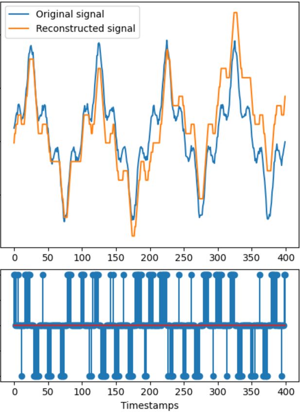
coding algorithms allow to encode the information with high         Algorithm 1: GRF-based population spike encoding
timing precision. The core idea of temporal coding is that              Data: input, m
spikes will be emitted whenever the variation of the signal             Result: spikes, minSig, maxSig
                                                                   1    L ← length(input)
gets higher than a threshold. Lastly, rate coding is used to       2    [minSig, maxSig] ← [min(input), max(input)]
encode the information into the spiking rate. An alternative       3    spikes ← zeros(L, m)
to these algorithms is to directly setup the encoding and          4    neurons ← zeros(m)
                                                                   5    for j = 1 : L do
decoding layers in the simulated SNN, and then train/evolve        6         for i = 1 : m do
the network itself. However, this approach is case-specific         7             µ = minSig + (2 · i − 3)/2 · (maxSig − minSig)/(m − 2)
and may not be supported by neuromorphic hardware.                  8             σ = (maxSig − minSig)/(m − 2)
                                                                    9             neurons(i) = norm(input( j), µ, σ )
   In this paper, we propose an overview of the different          10        [ , spikingNeuron] = max(neurons)
neuromorphic coding solutions available for applications in        11        spikes( j, spikingNeuron) = 1
robotics, with a set of MATLAB scripts and Python codes
implementing both encoding and decoding algorithms. A
benchmark is proposed to assess the interests of each of
                                                                   B. Rate coding schemes
the implemented methods, focusing on crucial aspects in
field robotics like how the information is encoded, but also          According to the rate coding paradigm, the information
the computational requirements and the coding efficiency           is encoded in the spiking rate instead of the specific spike
(i.e., quality of the signal reconstruction, number of spikes      timing. In this paper, we will focus on the following coding
generated, etc.). Lastly, we introduce a ROS (Robot Op-            algorithms:
erating System) package implementing these algorithms to              (i) The Hough Spike Algorithm (HSA): equivalent to a
enhance the use of neuromorphic solutions for robotics with               threshold-based mode, the HSA makes use of a reverse
traditional sensors (see Supplementary Materials).                        convolution between the buffered input signal with a
                                                                          finite impulse response (FIR) filter to determine the
          II. S PIKE CODING SCHEMES OVERVIEW                              spikes timings (Algorithm 2) [23].
                                                                     (ii) The Threshold Hough Spike Algorithm (T-HSA): sim-
A. Population coding schemes                                              ilar to the HSA, the T-HSA introduces a threshold to
                                                                          compare with the error between the signal and the filter
   Population coding has been shown to be widely used in
                                                                          (Algorithm 3) [24]. Whenever the error exceeds this
the brain (sensor, motor) [18], [19]. It suggests that neurons
                                                                          threshold, a spike is emitted, and the input signal is
(or populations of neurons) activity is determined by a
                                                                          updated by subtracting the filter response. In the T-
distribution over the input signal. A typical example of such
                                                                          HSA, the threshold depends on the signal and must be
coding has been extensively studied in ganglion cells of the
                                                                          determined prior to the encoding.
retina [20], [21], known to be the only neurons involved in
                                                                    (iii) The Ben’s Spike Algorithm (BSA): as for the previous
the transmission of the visual information from the retina to
                                                                          coding schemes, the BSA applies a reverse convolution
the brain. Studies in the somatosensory cortex, responsible
                                                                          of the signal with a FIR filter. To determine when a
for processing somatic sensations, also revealed the existence
                                                                          spike must be generated, the algorithm uses two errors,
of population coding [22].
                                                                          the first one being the sum of differences between the
   In this work, we implemented a quite simple model                      signal and the filter, and the second one being the
of population coding, further referred as GRF (Gaussian                   sum of the signal values. The algorithm then generates
Receptive Fields). Inspired by the aforementioned studies,                spikes by comparing the first error to a fraction of
the GRF model encodes the signal by means of a set of                     the accumulated signal, defined as the product be-
neurons which activity distributions are defined as Gaussian              tween the second error and a predefined threshold
waves determined by a centre µ and a variance σ 2 . In the                (Algorithm 4) [24]. Unlike T-HSA, the threshold is
proposed model, all centres µi of neurons i are regularly                 filter-dependent, allowing to keep the same value for
spaced to cover the maximum amplitude of the input signal,                different signals.
while the variances are set equal. At each timestamp, a spike
is generated from the neuron giving the highest response to           While rate coding is considered to be the universal way
the input signal (Algorithm 1).                                    neurons encode the information, many studies highlighted
   It is worth noting that the distribution of the Gaussian cen-   the poor performances of rate coding schemes as compared
tres µi is of great importance and depends on the application.     to temporal coding algorithms [25], [26].
While having a linear distribution allows to encode a signal
                                                                   C. Temporal coding schemes
in a homogeneous way, one could consider implementing a
Gaussian distribution instead. Therefore, the encoding would          Temporal representations, also called pulse coding, pro-
be better suited for neuromorphic control, with input being        vide a time-based coding where the information is encoded
the error to a targeted set point (e.g., thrust control based      in the exact spikes timing. Unlike rate coding, temporal
on the divergence of the optic flow field in a drone landing       coding provides more information capacity [27], and is
task [11]).                                                        further supported by neuro-physiological studies showing
Algorithm 2: Hough spike encoding                                                  Algorithm 5: Temporal contrast encoding
     Data: input, f ilter                                                               Data: input, α
     Result: spikes, shi f t                                                            Result: spikes, threshold
1    L ← length(input)                                                             1    L ← length(input)
2    F ← length( f ilter)                                                          2    spikes ← zeros(1, L)
3    spikes ← zeros(1, L)                                                          3    di f f ← zeros(1, L − 1)
4    shi f t ← min(input)                                                          4    for i = 1 : L − 1 do
5    input ← input − shi f t                                                       5          di f f (i) = input(i + 1) − input(i)
6    for i = 1 : L do                                                              6    threshold ← mean(di f f ) + α · std(di f f )
7           count ← 0                                                              7    di f f ← [di f f (1), di f f ]
8           for j = 1 : F do                                                       8    for i = 1 : L − 1 do
 9               if i + j + 1 ≤ L & input(i + j − 1) ≥ f ilter( j) then            9          if di f f (i) > threshold then
10                     count+ = 1                                                  10                spikes(i) = 1
11               if count == F then                                                11         else if di f f (i) < −threshold then
12                     spikes(i) = 1                                               12                spikes(i) = −1
13                     for j = 1 : F do
14                          if i + j + 1 ≤ L then
15                                input(i + j −1) = input(i + j −1)− f ilter( j)
                                                                                    Algorithm 6: Step-forward encoding
                                                                                        Data: input, threshold
 Algorithm 3: Threshold Hough spike encoding                                            Result: spikes, init
                                                                                   1    L ← length(input)
     Data: input, f ilter, threshold
                                                                                   2    spikes ← zeros(1, L)
     Result: spikes, shi f t
                                                                                   3    init, base ← input(1)
1    L ← length(input)
                                                                                   4    for i = 2 : L do
2    F ← length( f ilter)
                                                                                   5          if input(i) > base + threshold then
3    spikes ← zeros(1, L)
                                                                                    6              spikes(i) = 1
4    shi f t ← min(input)
                                                                                    7              base = base + threshold
5    input ← input − shi f t
                                                                                   8          else if input(i) < base − threshold then
6    for i = 1 : L do
                                                                                    9              spikes(i) = −1
7           error ← 0
                                                                                   10              base = base + threshold
8           for j = 1 : F do
 9               if i + j + 1 ≤ L & input(i + j − 1) ≥ f ilter( j) then
10                     error+ = f ilter( j) − input(i + j − 1)
11               if error ≤ threshold then
12                     spikes(i) = 1
13                     for j = 1 : F do                                            temporal coding with the phase information (encoding spatial
14                          if i + j + 1 ≤ L then                                  information in the ganglion cells) [30], [31]. Phase encoding
15                                input(i + j −1) = input(i + j −1)− f ilter( j)
                                                                                   has also been implemented in [32] to investigate on neurons
                                                                                   in the human auditory cortex. In this paper, we will focus
                                                                                   on the following coding algorithms:
 Algorithm 4: Ben’s spike encoding
     Data: input, f ilter, threshold                                                  (i) The Temporal-Based Representation (TBR): also
     Result: spikes, shi f t                                                              called temporal contrast, the TBR algorithm generates
1    L ← length(input)
2    F ← length( f ilter)                                                                 spikes whenever a the variation of the signal, between
3    spikes ← zeros(1, L)                                                                 two consecutive timestamps, gets higher than a fixed
4    shi f t ← min(input)                                                                 threshold (Algorithm 5) [33]. Event-based cameras
5    input ← input − shi f t
6    for i = 1 : (L − F) do                                                               such as the Dynamic Vision Sensor (DVS) implement
7           err1, err2 ← 0                                                                this coding scheme to generate a stream of events at
8           for j = 1 : F do                                                              extremely fast speed [33], [34].
 9               err1 = err1 + abs(input(i + j) − f ilter( j))
10               err2 = err2 + abs(input(i + j − 1))                                 (ii) The Step Forward Algorithm (SF): based on the
11          if err1 ≤ err2 · threshold then                                               TBR coding scheme, the SF uses a baseline signal
12               spikes(i) = 1                                                            to compute the variation of the input signal (Algo-
13               for j = 1 : F do
14                    if i + j + 1 ≤ L then                                               rithm 6) [35]. As for the TBR model, a spike (+1
15                          input(i + j + 1) = input(i + j + 1) − f ilter( j)             or −1) is emitted whenever the variation exceeds the
                                                                                          threshold. Simultaneously, the baseline gets updated by
                                                                                          ± the threshold depending on the spike polarity.
                                                                                    (iii) The Moving Window Algorithm (MW): the MW
that auditory and visual information are processed with high                              model is similar to the SF model, but here the baseline
precision in the brain [28].                                                              signal is defined as the mean of the previous signal
   Several models have been proposed. Assuming that the                                   intensities over a time window (Algorithm 7) [35].
most significant information is carried by the first spikes,
the Rank Order Coding (ROC) arranges spikes with respect                              Since SF and MW models feature an adaptive component
to their arrival time [26], [29]. Taking inspiration from                          in the calculation of the signal variations by means of the
the ganglion cells, the Latency-Phase Coding (LPC) was                             baseline, they are known to result in better reconstruction of
introduced to combine the exact time spiking provided by                           the encoded signal after decoding.
TABLE I
Algorithm 7: Moving window encoding AVERAGE SPIKING EFFICIENCY OF THE CODING SCHEMES
Data: input, window, threshold W. R . T. THE SIGNAL DURATION
Result: spikes, init
1 L ← length(input) TBR MW SF BSA HSA T-HSA
2 spikes ← zeros(1, L) Case #1 – T max = 1 sec (1 period), nb tests = 1000
3 init ← input(1) Mean 36.7 29.2 74.6 45.8 74.0 62.4
4 base ← mean(input(1 : (window + 1))) SD 4.1 3.4 2.0 1.8 1.3 1.1
5 for i = 1 : window + 1 do Case #2 – T max = 5 sec (5 periods), nb tests = 1000
6 if input(i) > base + threshold then Mean 36.7 27.5 73.4 33.1 64.5 57.5
7 spikes(i) = 1 SD 1.7 1.5 0.9 1.3 1.0 1.1
8 else if input(i) < base − threshold then Case #3 – T max = 15 sec (15 periods), nb tests = 1000
9 spikes(i) = −1 Mean 36.6 27.2 73.2 30.0 62.1 55.8
10 for i = window + 2 : L do SD 1.0 0.9 0.5 0.8 0.6 0.6
11 base = mean(input((i − window − 1) : (i − 1))) Case #4 – T max = 50 sec (50 periods), nb tests = 1000
12 if input(i) > base + threshold then Mean 36.7 27.1 73.2 29.3 61.6 55.6
13 spikes(i) = 1 SD 0.6 0.5 0.3 0.4 0.3 0.3
14 else if input(i) < base − threshold then Case #5 – T max = 100 sec (100 periods), nb tests = 1000
15 spikes(i) = −1 Mean 36.6 27.1 73.2 29.0 61.4 55.5
SD 0.4 0.3 0.2 0.2 0.2 0.2
D. Comparison of the selected schemes TABLE II
AVERAGE RMSE BETWEEN THE ORIGINAL AND THE
The selected algorithms, i.e., GRF, TBR, SF, MW, BSA,
RECONSTRUCTED SIGNALS W. R . T. THE SIGNAL DURATION
HSA, and T-HSA, have all been implemented both in MAT-
LAB and Python 3 (encoding and decoding algorithms; see TBR MW SF BSA HSA T-HSA
Supplementary Materials). In this section, we propose to Case #1 – T max = 1 sec (1 period), nb tests = 1000
investigate on their performances by means of a benchmark Mean 0.80 0.68 0.26 0.84 0.97 0.68
SD 0.39 0.24 0.01 0.04 0.05 0.03
over a set of 1D signals (sum of noisy sine waves). An Case #2 – T max = 5 sec (5 periods), nb tests = 1000
overview of the typical outputs provided by each algorithm is Mean 1.41 1.11 0.26 0.64 0.62 0.39
shown in Fig. 1(A-G). Qualitatively, it is worth noting that SD 0.68 0.54 0.01 0.02 0.03 0.01
Case #3 – T max = 15 sec (15 periods), nb tests = 1000
both the quality of the signal reconstruction and the effi- Mean 2.24 1.74 0.26 0.60 0.51 0.30
ciency in spike encoding vary from one model to another. In SD 1.17 0.86 0.00 0.01 0.02 0.06
the following, we define spiking efficiency as the percentage Case #4 – T max = 50 sec (50 periods), nb tests = 1000
Mean 3.90 2.94 0.26 0.58 0.48 0.26
of timestamps without spike emission: SD 2.00 1.57 0.00 0.00 0.01 0.00
Case #5 – T max = 100 sec (100 periods), nb tests = 1000
Mean 5.55 4.14 0.26 0.57 0.46 0.25
spike count
SD 2.98 2.17 0.00 0.00 0.01 0.00
spiking efficiency = 1 − × 100 (1)
length o f the signal
These observations are further investigated by assessing
the spiking efficiency of each algorithm as well as the root
mean squared error (RMSE) between the input signal and performances, showing no significant effect of the signal
the reconstructed one over a set of N = 1000 samples. The duration, and with an overall RMSE as low as 0.26 ± 0.01
long-term drift, due to cumulative errors in the signal recon- (mean ± standard deviation), while the amplitude of the input
struction, are also considered by extending the duration of the signal is equal to 5.8. Besides, we note that the performance
signal from 5 seconds to 100 seconds. Statistical results are of the rate coding (BSA, HSA, and T-HSA) tend to improve
given in Tables I (spiking efficiency) and II (RMSE). First, as the signal duration increases, with a final average RMSE
we observe that algorithms SF, HSA, and T-HSA result in a inferior to 0.6. As for the spiking efficiency, algorithms SF,
high spiking efficiency (> 50%). In particular, we note that BSA, HSA, and T-HSA tend to stabilize their mean RMSE
the SF model is not affected by the duration of the signal with increased signal duration, thus reflecting the existence
(stable at 73%), while the spiking efficiency of rate coding of an optimum. However, the temporal coding TBR and MW
HSA and T-HSA drops 13 (HSA) and 7 (T-HSA) points, show an increasing RMSE, reaching the amplitude of the
respectively. In contrast, the MW scheme maintains a spiking input signal itself after 100 periods. As shown in Fig. 2,
efficiency of 27%, regardless of the signal duration. Lastly, these algorithms accumulate errors over time and tend to
it is interesting to note that the standard deviation of the drift from the input, while the wave form of the signal is
spiking efficiency tends to 0 when the signal duration gets maintained.
bigger. This suggest that for each algorithm, and certainly for Lastly, the GRF population coding scheme shows accurate
each type of signal, an optimal duration of the signal ensures signal reconstruction for as long as enough encoding neurons
stable spiking efficiency. Fig 1(H) shows an example of the are available (Fig. 1G). However, the computational cost
spiking efficiency over the 1000 sample tests (case 3). grows with the coding neurons, and the spiking efficiency
The quality of the reconstruction is reflected by the is null: a spike is emitted at each timestamp, resulting in a
RMSE. Once again, the SF model demonstrates the best loss in the spike timing accuracy.Fig. 1. Example of the typical outputs of the selected coding schemes on a 1D signal. A-C Temporal coding. D-F Rate coding. G Population coding. For
each coding scheme (A-G), the original (blue) and the reconstructed (orange) signals are displayed (top), as well as the corresponding spikes (bottom).
H Coding efficiency of the different methods, expressed as a percentage. Yellow: SF. Green: HSA. Cyan: T-HSA. Blue: TBR. Purple: BSA. Orange: MW.
produce a great number of spikes), and their performances
depend on the type of filter (which itself depends on the
data encoded). On the positive side, they are quite robust to
disturbances (very low RMSE after reconstruction). Table III
provides an overview of the parameters required to deploy
each algorithm. These parameters care mostly case specific
and must be determined prior to the online robotic applica-
tion. A straightforward approach for this would be the use
of evolutionary algorithms within Python-based frameworks
like DEAP [36], PyBrain [37] and PyEvolve [38].
TABLE III
PARAMETERS REQUIRED FOR EACH CODING SCHEME
TBR MW SF BSA HSA T-HSA GRF
Factor x
Threshold x x x x
Window x
Filter x x x
Neurons x
III. A ROS PACKAGE PROPOSAL
A. Description of the package
Fig. 2. Typical drift of the reconstructed signals for both the TBR (top) With the aim of reducing the sensing bottleneck and
and the MW (bottom) temporal coding schemes (N = 1000 samples).
therefore stimulating investigations in neuromorphic AI for
robotics, we propose an ROS implementation of the afore-
mentioned coding schemes (GRF, TBR, MW, SF, BSA, HSA,
E. Summary
and T-HSA; see Supplementary Materials). Both encoding
When it comes to robotic applications, it is of high and decoding algorithms are implemented in Python, in the
importance to balance the overall performances of the coding same scripts as those described in the previous section. The
schemes with the available computational resources and provided ROS tools are organized as follows:
the type of information to process. For instance, the GRF (i) The spyke msgs package introduces two new type
population coding algorithm allows to precisely encode the of ROS messages, i.e. spyke.msg which contains the
value of the input signal, while temporal and rate coding spike (+1, 0, −1), the corresponding timestamp (in
schemes will rather encode the temporal variations. Rate seconds), and a set of parameters that depend on the
coding schemes can be greedy in the way that they require signal and the coding scheme. The second message,
buffered signals to achieve good performances. They also spyke array.msg is a copy of the previous one but
suffer from major limitations as they are inefficient (i.e., they designed for carrying an array of spikes instead.(ii) The spyke coding schemes package contains the en-
coding and decoding functions to be installed in the
ROS workspace.
(iii) The spyke coding package defines the ROS node to be
launched to start encoding or decoding an input signal.
Once active, the ROS node will publish the message
and record the data in a rosbag located at ∼/.ros/. We
also provide a Python script to process the data.
The ROS node can be launched as usual by running the
following command: roslaunch spyke coding .
A set of launch files for each implemented coding
scheme is available within the spyke coding package.
To facilitate the use of the package, the ROS node
(spyke coding/src/generate spikes.py) simulates a 1D signal
to be encoded. This can be easily replaced by a ROS
subscriber to any sensor available.
B. Examples
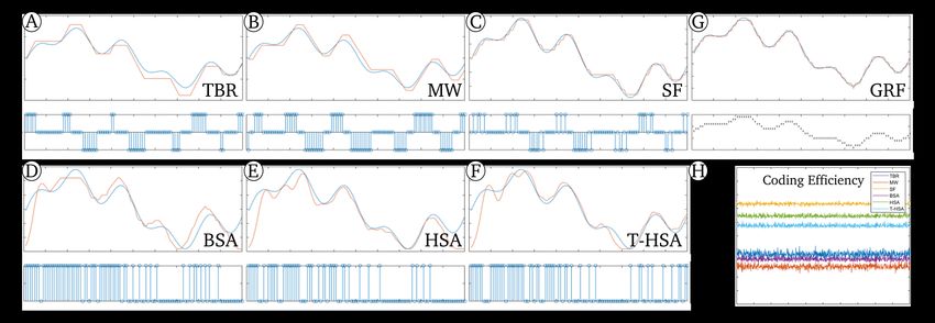
Here we provide an example of the output signals provided
by the ROS toolbox. In this example, we consider an input
signal of 4 seconds with a sampling frequency of 100 Hz.
The signal is defined as the sum of three sine waves of
frequencies 1 Hz, 2 Hz, and 5 Hz. Noise is added to the
signal. The encoding scheme selected is the SF model for
which the threshold is equal to 0.35. A Python script is
available for automatic processing of rosbags. In Fig. 3, the Fig. 3. Example of the spike generation in ROS using the SF algorithm.
(Top) Graphic representation of the original (blue) and reconstructed (or-
recorded data, i.e., the input signal and the generated spikes, ange) signals. (Bottom) Spikes generated by the encoding scheme. Time:
are displayed along with the reconstructed signal. one timestamp equals 0.01 seconds.
IV. C ONCLUSIONS AND FUTURE WORK
ACKNOWLEDGEMENTS
We introduced a toolbox for neuromorphic coding for
sensing in robotics with the aim to facilitate the development This work is part of the Comp4Drones project and has
of fully neuromorphic systems onboard robots, from percep- received funding from the ECSEL Joint Undertaking (JU)
tion to action. It includes the seven following algorithms: under grant agreement No. 826610. The JU receives support
the Gaussian Receptive Fields (GRF) population coding, the from the European Union’s Horizon 2020 research and
Temporal-Based Representation (TBR, also used in event- innovation program and Spain, Austria, Belgium, Czech
based cameras), the Step-Forward (SF) and the Moving Republic, France, Italy, Latvia, Netherlands.
Window (MW) algorithms, as well as the following rate-
based coding schemes: the Ben’s Spike Algorithm (BSA),
R EFERENCES
the Hough Spike Algorithm (HSA) and the Threshold Hough
Spike Algorithm (T-HSA). The toolbox contains implemen- [1] C. Pehle and J. E. Pedersen, “Norse - A deep learning
tations of the encoding and decoding algorithms in MATLAB library for spiking neural networks,” Jan. 2021, documentation:
and Python, and have been integrated to the ROS framework https://norse.ai/docs/. [Online]. Available: https://doi.org/10.5281/
zenodo.4422025
to encode and decode signals online onboard robots. A [2] D. F. Goodman and R. Brette, “Brian: a simulator for spiking neural
benchmark has been proposed to assess the advantages and networks in python,” Frontiers in neuroinformatics, vol. 2, p. 5, 2008.
drawbacks of each of the proposed coding schemes. [3] T. Bekolay, J. Bergstra, E. Hunsberger, T. DeWolf, T. C. Stewart,
D. Rasmussen, X. Choo, A. Voelker, and C. Eliasmith, “Nengo: a
This toolbox is expected to evolve, with the will to python tool for building large-scale functional brain models,” Frontiers
integrate other coding schemes like the non-linear GRF pop- in neuroinformatics, vol. 7, p. 48, 2014.
ulation coding, the Rank Order Coding (ROC), the Latency- [4] J. Schemmel, D. Brüderle, A. Grübl, M. Hock, K. Meier, and S. Mill-
ner, “A wafer-scale neuromorphic hardware system for large-scale
Phase temporal Coding (LPC), etc. neural modeling,” in 2010 IEEE International Symposium on Circuits
and Systems (ISCAS). IEEE, 2010, pp. 1947–1950.
S UPPLEMENTARY MATERIALS [5] B. V. Benjamin, P. Gao, E. McQuinn, S. Choudhary, A. R. Chan-
drasekaran, J.-M. Bussat, R. Alvarez-Icaza, J. V. Arthur, P. A. Merolla,
and K. Boahen, “Neurogrid: A mixed-analog-digital multichip system
The MATLAB, Python and ROS codes are available at: for large-scale neural simulations,” Proceedings of the IEEE, vol. 102,
https://github.com/tudelft/SpikeCoding. no. 5, pp. 699–716, 2014.[6] P. A. Merolla, J. V. Arthur, R. Alvarez-Icaza, A. S. Cassidy, J. Sawada, [28] C. E. Carr, “Processing of temporal information in the brain,” Annual
F. Akopyan, B. L. Jackson, N. Imam, C. Guo, Y. Nakamura, et al., “A review of neuroscience, vol. 16, no. 1, pp. 223–243, 1993.
million spiking-neuron integrated circuit with a scalable communica- [29] L. Perrinet, M. Samuelides, and S. Thorpe, “Coding static natural
tion network and interface,” Science, vol. 345, no. 6197, pp. 668–673, images using spiking event times: do neurons cooperate?” IEEE
2014. Transactions on neural networks, vol. 15, no. 5, pp. 1164–1175, 2004.
[7] S. B. Furber, F. Galluppi, S. Temple, and L. A. Plana, “The spinnaker [30] Z. Nadasdy, “Information encoding and reconstruction from the phase
project,” Proceedings of the IEEE, vol. 102, no. 5, pp. 652–665, 2014. of action potentials,” Frontiers in systems neuroscience, vol. 3, p. 6,
[8] M. Davies, N. Srinivasa, T.-H. Lin, G. Chinya, Y. Cao, S. H. Choday, 2009.
G. Dimou, P. Joshi, N. Imam, S. Jain, et al., “Loihi: A neuromorphic [31] J. Hu, H. Tang, K. C. Tan, H. Li, and L. Shi, “A spike-timing-based
manycore processor with on-chip learning,” Ieee Micro, vol. 38, no. 1, integrated model for pattern recognition,” Neural computation, vol. 25,
pp. 82–99, 2018. no. 2, pp. 450–472, 2013.
[9] C. Frenkel, J.-D. Legat, and D. Bol, “A 28-nm convolutional neuromor- [32] J. Wu, Y. Chua, M. Zhang, H. Li, and K. C. Tan, “A spiking
phic processor enabling online learning with spike-based retinas,” in neural network framework for robust sound classification,” Frontiers
2020 IEEE International Symposium on Circuits and Systems (ISCAS). in neuroscience, vol. 12, p. 836, 2018.
IEEE, 2020, pp. 1–5. [33] P. Lichtsteiner and T. Delbruck, “A 64x64 aer logarithmic temporal
[10] R. K. Stagsted, A. Vitale, A. Renner, L. B. Larsen, A. L. Christensen, derivative silicon retina,” in Research in Microelectronics and Elec-
and Y. Sandamirskaya, “Event-based pid controller fully realized tronics, 2005 PhD, vol. 2. IEEE, 2005, pp. 202–205.
in neuromorphic hardware: a one dof study,” in 2020 IEEE/RSJ [34] P. Lichtsteiner, C. Posch, and T. Delbruck, “A 128x128, 120 db, 15 us
International Conference on Intelligent Robots and Systems (IROS). latency asynchronous temporal contrast vision sensor,” IEEE journal
IEEE, 2020, pp. 10 939–10 944. of solid-state circuits, vol. 43, no. 2, pp. 566–576, 2008.
[11] J. Dupeyroux, J. Hagenaars, F. Paredes-Vallés, and G. de Croon, [35] N. Kasabov, N. M. Scott, E. Tu, S. Marks, N. Sengupta, E. Capecci,
“Neuromorphic control for optic-flow-based landings of mavs using M. Othman, M. G. Doborjeh, N. Murli, R. Hartono, et al., “Evolving
the loihi processor,” arXiv preprint arXiv:2011.00534, 2020. spatio-temporal data machines based on the neucube neuromorphic
[12] C. Michaelis, A. B. Lehr, and C. Tetzlaff, “Robust trajectory generation framework: Design methodology and selected applications,” Neural
for robotic control on the neuromorphic research chip loihi,” Frontiers Networks, vol. 78, pp. 1–14, 2016.
in neurorobotics, vol. 14, 2020. [36] F.-A. Fortin, F.-M. De Rainville, M.-A. G. Gardner, M. Parizeau, and
[13] I. Polykretis, G. Tang, and K. P. Michmizos, “An astrocyte-modulated C. Gagné, “Deap: Evolutionary algorithms made easy,” The Journal
neuromorphic central pattern generator for hexapod robot locomotion of Machine Learning Research, vol. 13, no. 1, pp. 2171–2175, 2012.
on intel’s loihi,” in International Conference on Neuromorphic Systems [37] T. Schaul, J. Bayer, D. Wierstra, Y. Sun, M. Felder, F. Sehnke,
2020, 2020, pp. 1–9. T. Rückstieß, and J. Schmidhuber, “Pybrain,” Journal of Machine
[14] G. Gallego, T. Delbruck, G. M. Orchard, C. Bartolozzi, B. Taba, Learning Research, vol. 11, no. ARTICLE, pp. 743–746, 2010.
A. Censi, S. Leutenegger, A. Davison, J. Conradt, K. Daniilidis, and [38] C. S. Perone, “Pyevolve: a python open-source framework for genetic
D. Scaramuzza, “Event-based vision: A survey,” IEEE Transactions algorithms,” Acm Sigevolution, vol. 4, no. 1, pp. 12–20, 2009.
on Pattern Analysis and Machine Intelligence, pp. 1–1, 2020.
[15] B. Petro, N. Kasabov, and R. M. Kiss, “Selection and optimization of
temporal spike encoding methods for spiking neural networks,” IEEE
transactions on neural networks and learning systems, vol. 31, no. 2,
pp. 358–370, 2019.
[16] B. Meftah, O. Lézoray, S. Chaturvedi, A. A. Khurshid, and A. Benyet-
tou, “Image processing with spiking neuron networks,” in Artificial
Intelligence, Evolutionary Computing and Metaheuristics. Springer,
2013, pp. 525–544.
[17] Q. Liu, G. Pineda-Garcı́a, E. Stromatias, T. Serrano-Gotarredona, and
S. B. Furber, “Benchmarking spike-based visual recognition: a dataset
and evaluation,” Frontiers in neuroscience, vol. 10, p. 496, 2016.
[18] A. P. Georgopoulos, A. B. Schwartz, and R. E. Kettner, “Neuronal
population coding of movement direction,” Science, vol. 233, no. 4771,
pp. 1416–1419, 1986.
[19] B. B. Averbeck, P. E. Latham, and A. Pouget, “Neural correlations,
population coding and computation,” Nature reviews neuroscience,
vol. 7, no. 5, pp. 358–366, 2006.
[20] S. Nirenberg and P. E. Latham, “Population coding in the retina,”
Current Opinion in Neurobiology, vol. 8, no. 4, pp. 488–493, 1998.
[21] D. K. Warland, P. Reinagel, and M. Meister, “Decoding visual
information from a population of retinal ganglion cells,” Journal of
neurophysiology, vol. 78, no. 5, pp. 2336–2350, 1997.
[22] R. S. Petersen, S. Panzeri, and M. E. Diamond, “Population coding
in somatosensory cortex,” Current opinion in neurobiology, vol. 12,
no. 4, pp. 441–447, 2002.
[23] M. Hough, H. De Garis, M. Korkin, F. Gers, and N. E. Nawa, “Spiker:
Analog waveform to digital spiketrain conversion in atr’s artificial
brain (cam-brain) project,” in International conference on robotics and
artificial life, vol. 92. Citeseer, 1999.
[24] B. Schrauwen and J. Van Campenhout, “Bsa, a fast and accurate
spike train encoding scheme,” in Proceedings of the International
Joint Conference on Neural Networks, 2003., vol. 4. IEEE, 2003,
pp. 2825–2830.
[25] J. Gautrais and S. Thorpe, “Rate coding versus temporal order coding:
a theoretical approach,” Biosystems, vol. 48, no. 1-3, pp. 57–65, 1998.
[26] R. V. Rullen and S. J. Thorpe, “Rate coding versus temporal order
coding: what the retinal ganglion cells tell the visual cortex,” Neural
computation, vol. 13, no. 6, pp. 1255–1283, 2001.
[27] M. Abeles, Y. Prut, H. Bergman, and E. Vaadia, “Synchronization in
neuronal transmission and its importance for information processing,”
Progress in brain research, vol. 102, pp. 395–404, 1994.You can also read