A Workflow Development Framework - for the .NET Platform
←
→
Page content transcription
If your browser does not render page correctly, please read the page content below
A Workflow Development Framework
                    for the .NET Platform

                          Adam Smith
              Computing with Management (Industry)
                       Session 2005/2006

The candidate confirms that the work submitted is their own and the appropriate credit has
been given where reference has been made to the work of others.

I understand that failure to attribute material which is obtained from another source may be
considered as plagiarism.

                                   (Signature of student) ________________________________

                                             i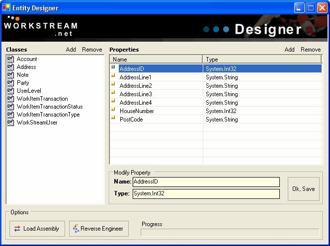
Summary
The aim of this project is to produce an open-source workflow development framework for
the .NET platform, which will seek to provide developers with a toolkit to construct a
bespoke workflow system for their business scenario.

This project explores the workflow domain, software development methodologies and the
different technical approaches available for implementing the various components. Such
technical analysis will include discussions on, but not limited to; distributed computing (Web
Services & CORBA), Object-Relational Mapping, ADO.NET, ASP.NET and scheduling.

The system is then evaluated and conclusions regarding the success of the project are drawn,
to include feedback from a .NET professional with workflow development experience.

                                               i
Acknowledgements
Firstly, I would like to thank Natasha Shakhlevich and Nick Efford for their valuable
feedback throughout the project.
I would also like to thank Gordon Eddie for kindly agreeing to review the final product – I
look forward to working (all the hours god sends) with you next year.
A big thank-you must also go out to those who proof read this report; Lois, Tony Smith and
Charles Donald.
Finally, I would like to thank Jack Bauer for keeping me entertained throughout the project.
Tony, Edgar, President Palmer & Michelle – you will be dearly missed.
iiTable of Contents
1. Introduction.............................................................................................................1
1.1 Problem Definition..........................................................................................1
1.2 Project Aim & Objectives ...............................................................................1
1.3 Minimum Requirements..................................................................................2
1.4 Project Deliverables ........................................................................................2
1.5 Relevance to Degree .......................................................................................2
2. Project Management...............................................................................................3
2.1 Introduction .....................................................................................................3
2.2 System Design Methodologies........................................................................3
2.3 Project Schedule..............................................................................................6
3. Workflow Management Systems ...........................................................................7
3.1 Introduction .....................................................................................................7
3.2 What is Workflow? .........................................................................................7
3.3 Current Workflow Management Systems.......................................................8
3.4 Conclusions .....................................................................................................9
4. Requirements Specification..................................................................................12
4.1 Introduction ...................................................................................................12
4.2 Component Specifications ............................................................................12
5. Technical Analysis.................................................................................................13
5.1 Introduction ...................................................................................................13
5.2 About Microsoft .NET ..................................................................................13
5.3 Database Selection ........................................................................................14
5.4 Data Access Layer.........................................................................................15
5.5 Work Request Submission: Platform independent method calls ..................19
6. System Design........................................................................................................20
6.1 Introduction ...................................................................................................20
6.2 Data Access Layer.........................................................................................20
6.3 Work Request Submission ............................................................................23
6.4 Workflow Engine ..........................................................................................23
6.5 Workflow Activity Block..............................................................................25
6.6 Web-based User Interface .............................................................................26
6.7 Fitting it together: The “Big Picture”............................................................27
6.8 Work Item Scheduler ....................................................................................27
7. Implementation .....................................................................................................28
7.1 Introduction ...................................................................................................28
7.2 General Deployment .....................................................................................28
7.3 Data Access Layer: The ORM ......................................................................28
7.4 Work Request Submission (Web Service)....................................................32
7.5 Workflow Engine ..........................................................................................33
7.6 Activity Block ...............................................................................................35
7.7 Web-based User Interface .............................................................................35
7.8 Work Item Scheduler ....................................................................................39
8. Testing ....................................................................................................................41
8.1 Introduction ...................................................................................................41
8.2 Unit Testing...................................................................................................41
8.2 Integration Testing ........................................................................................41
iii8.3 End-to-End Testing .......................................................................................41
9. Evaluation ..............................................................................................................43
9.1 Introduction ...................................................................................................43
9.2 Aims, Objective and Minimum Requirements..............................................43
9.3 Project Enhancements ...................................................................................44
9.4 Evaluation of Project Approach ....................................................................45
9.5 Evaluation of Background Research.............................................................46
9.6 Evaluation of Design.....................................................................................46
9.7 Evaluation of Implementation.......................................................................47
9.8 Possible Future Enhancements......................................................................48
9.9 Evaluation from .NET Workflow Professionals ...........................................49
References ..................................................................................................................50
Appendix A – User Reflection..................................................................................53
Appendix B – Project Schedule................................................................................55
Initial (Pre-research) Gantt Chart........................................................................55
Predicted Progress...............................................................................................56
Actual Progress ...................................................................................................57
Appendix C – Design.................................................................................................58
Entity-Relationship Diagram ..............................................................................60
ORM Classes.......................................................................................................61
Workflow Engine ................................................................................................64
Work Item Scheduler ..........................................................................................66
Web-based GUI...................................................................................................67
Entity Forward Engineering Tool .......................................................................68
Code Generation..................................................................................................69
Mapping Generation............................................................................................70
Appendix D – Implementation.................................................................................71
Entity Forward Engineering Tool .......................................................................71
Work Request Submission - WSDL ...................................................................72
Appendix E – Evaluation..........................................................................................74
Developer Feedback............................................................................................74
iv1. Introduction
1.1 Problem Definition
The problem was first observed during an industrial placement whilst engaged on a large .NET
workflow development project for a major financial services provider.
The project’s design & build phases began completely from scratch; with a large part of the initial
build effort concentrated solely on developing various fundamental workflow mechanisms. These
mechanisms represented the common basic components required for a workflow system to actually
function, for example; how a request for work is inputted, how a workflow is selected & processed,
how the system should communicate with persistent storage, and so on. This scenario embodied a key
problem; creating fundamental elements of workflow functionality from scratch each time removes
initial focus and development effort away from the business use cases, which is inefficient for both
parties as core workflow functionality is perfectly foreseeable and thus could be pre-prepared.
1.2 Project Aim & Objectives
The overall aim of the project is to produce an open-source workflow development framework for
the .NET platform, which will seek to provide developers with a toolkit to construct a bespoke
workflow system for their business scenario.
Gamma et al define a framework as “a set of cooperating classes that make up a reusable design for a
specific class of software” [28]. In this context, the framework will aim to capture the design
decisions that are common to the workflow domain, thereby pre-defining a series of extendable
components to enable a business developer to concentrate on the specifics of their application. As
such, the objective is to produce the following components:
· Data Access Layer (DAL) – To allow customisable communication with a database in a
productive, simplified manner.
· Work Request Submission/Creation – To ensure “requests” for work can be entered in a
platform independent way.
· Workflow Engine – A configurable “controller”, that manages the behaviour of a workflow.
· Workflow Activity Block – A base component allowing new workflow activities to be
specified in a common manner, and controlled by the Workflow Engine.
· Web-based user interface – A skeleton UI framework which ties together each of the above
components into a working graphical system.
11.3 Minimum Requirements
The minimum requirements that must be achieved in order to meet the aims of the project are:
· To produce a series of interlinked base-components that can be extended by business
developers to produce a bespoke workflow system.
· To demonstrate and test the usage of these components by utilising the framework to create a
series of sample workflow transactions.
1.3.1 Possible Enhancements Above & Beyond Minimum Requirements
The following list represents a series of enhancements that could be made to further extend the
functionality of the framework, if time allows.
· Work Item Scheduler – To allow for the automatic execution of multiple “Work Items” at a
specified time.
· Distributable Components - To allow each of the components (as mentioned in Section 1.2)
to be deployed across multiple machine boundaries with communication occurring via
remotable interfaces.
· Code Generation/Forward Engineering – This technique allows code to be automatically
generated from (mostly) visual models, thereby removing time intensive and laborious tasks
from the developer’s workload.
1.4 Project Deliverables
The framework deliverable will consist of:
· A software design
· A database design
· A .NET application (the framework components)
· A database back-end
1.5 Relevance to Degree
This project will draw upon skills gained from a wide range of taught modules within the School of
Computing. Topics from Information Systems (IN11) will allow for the formation of a suitable
methodology and project plan. Techniques from object-orientated programming (SE21), Internet
Systems Technologies (SY23) and Distributed Systems (SY33) will be used for the implementation of
the web-based solution. With knowledge acquired from Database Principles & Practice (DB21) being
used to aid in the design and implementation of the SQL database back-end.
22. Project Management
2.1 Introduction
Dictionary definitions of the term “project” place a clear emphasis on it being a “planned” activity [1]
[2] - that is to say, something you think carefully about before you do it. This chapter will seek to
determine how best to carry out the project by discussing project management, methodologies and
schedules.
As an effective plan must be based upon some idea of a method of work [3], the following section will
discuss the various software development methodologies available.
2.2 System Design Methodologies
Avison & Fitzgerald define a system methodology as “A recommended collection of phases,
procedures, rules, techniques, tools, documentation, management and training used to develop a
system”. [4]
2.2.1 Why use a methodology?
There are many justifications for using a methodology to guide development, according to Fitzgerald
the key reasons are [5]:
· The subdivision of a complex process into manageable tasks.
· Facilitation of project management and control.
· Purposeful framework for applying techniques.
· Economics – the division of labour to carry out specific tasks of their speciality.
· Standardisation – developers are interchangeable.
However, for many organisations the use of development methodologies has not always yielded
positive results, with real world performance actually causing many developers to discard them [4].
As such, several development projects have rejected the use of methodologies all together, adopting
for a more flexible ad-hoc approach. This is particularly the case in web-based projects which are
typically developed in a “trial and error fashion, relying on the skills and experience of the
developers” to complete the application successfully [4].
The key point of consideration for this project is the author’s lack of experience in the field of .NET
applications – only 1 year – accordingly, a methodology will be used to help guide the development
process in the right direction.
3There are a diverse range of methodologies available, therefore it is necessary to explore several of the
options to find a suitable fit. The following will be examined in greater detail in order to establish
their potential application within this project: Waterfall, The Rational Unified Process (RUP) and
Structured Systems Analysis and Design Methodology (SSADM).
2.2.2 The Waterfall Model
The Waterfall model “subdivides the development process into formal stages where the output of one
stage forms the input for the next” [5]. The idea is to progress from one stage to the next in a purely
sequential manner, achieving end user sign-off at the end of each section. This aspect has obvious
advantages as it ensures a developer can only move on when the previous stage is to the end users
liking. This could potentially lead to more economical project management – a key consideration as it
is estimated that requirements errors cost 200 times more to fix if not discovered before the
implementation phase [5].
The clear separation of distinct tasks (due to frozen deliverables) would also allow for easier progress
measurements, particularly when using milestones as a key progress indicator. This certainly has
positive time management implications.
Whilst the orderly, systematic and stepwise approach to problem solving is appealing, a major concern
is that of inflexibility. The life cycle assumes that requirements can defined in reasonable detail and
articulated accordingly before the design phase begins – it therefore assumes that requirements are
fixed thus disallowing modifications as the project unfolds [5]. Frequent and incremental builds are
also not possible under this approach [6], this is of particular concern as such techniques are often
required to actually put design concepts into practice, thus avoiding mammoth problems come
deployment.
Where requirements can be articulated clearly and the developers have in-depth experience of the
particular application domain there is a definite argument for adopting the Waterfall approach.
However, the model places numerous restraints on flexibility and indeed the basic ability of one phase
to learn (and adapt) from the previous one. As the requirements for this project are loosely defined, an
increasing understanding of the problem through successive refinements and incremental growth is
likely to play a vital role in producing an effective solution – as such the Waterfall model is not
suitable.
42.2.3 The Rational Unified Process (RUP)
The Rational Unified Process is an iterative lifecycle approach that is particularly suited to UML. The
process’s activities emphasize the “creation and maintenance of models rather than paper documents”
[7] – the idea being to provide rich visual representations of system.
The key emphasis on modelling allows developers to “visualise, specify, construct and document the
structure of a system’s architecture in a simplified way” [8], which fully describe the solution. This
greatly improves a developer’s ability to manage and understand software complexity [8].
In particular, the process stresses the importance of developing software in an iterative fashion [9].
By recognising that it is not possible to define the problem and build the solution in a single step,
iterative and continuous improvement pulls risk back in time, ensuring mistakes are remedied during
the earlier phases. This also allows projects to evolve, as each iteration will inform and shape the
other.
2.2.4 Structured Systems Analysis and Design Methodology (SSADM)
Structured Systems Analysis and Design Methodology (SSADM) is a methodology that focuses on the
earlier stages of a software development – analysis and design.
As such, systems closely match users’ needs because these are made clear from the outset during the
initial stages.
The 3 most important techniques that are used in SSADM are [10]: Logical Data Modelling - the
process of identifying, modelling and documenting the data requirements of the system being
designed. Data Flow Modelling - the process of identifying, modelling and documenting how data
moves around an information system. Entity behaviour modelling - the process of identifying,
modelling and documenting the events that affect each entity and the sequence in which these events
occur.
SSADM does not, however, cover the construction, testing or implementation of software. It also
builds each step upon the work that was prescribed in the previous step – with no deviations allowed.
Due to its rigid structure and ignorance towards the latter project stages SSADM is not suitable.
2.2.5 Justification of Choice
Following review of the above methodologies a decision has been made to adopt the Rational Unified
Process (RUP), primarily on the following grounds:
5Its iterative approach allows for the identification of risks early on in the project, therefore avoiding
any last minute struggles [8]. Specifically, this will allow each key stage of design & implementation
to go through two iterations (See Section 2.3).
In Section 1.2, the first minimum requirement was separated into five measurable components. This
approach neatly fits with RUP’s emphasis on Component-based development (CBD). As each stage
produces an output capable of being measured, tested and evaluated the quality of the software can be
verified allowing for the requisite adjustments to be made. CBD also fits well when developing
frameworks as it enables further reuse and customisation [8].
The use of UML (Unified Modelling Language) modelling will completely describe the system from a
consistent and simplified perspective. The author is personally familiar with UML having used it on
several university modules and in the real world as a lead package designer producing technical
designs for an offshore (Indian) build team. The other important consideration is that UML is a
widely-accepted standard; as such the framework design presented in this project should be easily
understood by readers (and of course any real-world developers using the product).
2.3 Project Schedule
All three Gantt charts indicating; initial (pre-research), predicted (post research) and actual progress
can be found within Appendix B The predicted & actual plans follow the iterative doctrine of the
chosen methodology (RUP), consequently, the design and implementation stages have been broken
down into measurable components and will go through two iterations each.
The project has been split to form seven key milestone deliverables:
· M1 – Marks the completion of Requirements Modelling.
· M2 – Marks the completion (both iterations) Data Access Layer Design & Implementation.
· M3 – Marks the completion (both iterations) of Work Request Input Design & Implementation.
· M4 – Marks the completion (both iterations) of Workflow Engine + Workflow Activity Block
Design & Implementation.
· M5 – Marks the completion of (both iterations) GUI Design & Implementation.
Upon the completion of M5, the first minimum requirement will have been met.
· M6 – Marks the completion of testing (i.e. producing a series of sample transactions).
Upon the completion of M6, the second minimum requirement will have been met.
· M7 - Marks the completion of the final report.
63. Workflow Management Systems
3.1 Introduction
This chapter will provide an introduction to workflow, then go on to contrast the Java & .NET
workflow landscapes and end with a critical discussion of the current workflow products available.
3.2 What is Workflow?
In its raw form a workflow is essentially a business process, which in turn can be defined as “a set of
one or more linked activities that collectively realise a business objective” [11]. An example would be
the process of granting a customer loan.
The make-up of each workflow is specified within a process definition, which is used to “analyse,
model, describe and document a business process” [12]. This, in effect, states how business activities
string together to complete a business process. Process definitions are then interpreted and executed
by a workflow engine, which is defined as “a software service or engine that provides the run time
execution environment for a workflow instance”. This project will refer to workflow instances as
Work Item Transactions – that is, a specific unit of work of a particular type (i.e. a Work Item
Transaction Type) [12].
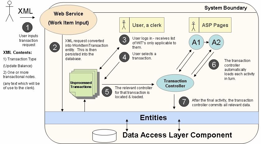
The Workflow Management Coalition sums up the process thus; a work item is created, is processed
and changed in stages at a number of processing points to meet business goals.
The above statement can be better viewed in context by applying it to the real-life business scenario of
granting a customer loan.
3.2.2 A Working Example: Granting a customer loan
An application is made using the loan company website, where all the relevant information is entered
electronically. The request is then submitted to the company’s workflow management system
(WfMS) where it becomes an unprocessed Work Item Transaction, of type “Loan Request”.
Most workflows comprise a number of logical steps, each of which is known as an activity. An
activity can either involve manual interaction with a clerk (a so-called workflow participant), or can be
executed automatically using machine resources [13]. The Loan Request workflow is likely to contain
a mixture of both activity types, and as such will be assigned by the WfMS to a clerk (workflow
participant) with the appropriate skills. The system will process each activity according to a pre-
defined order (as per process definition); the first activity might automatically send the customer an e-
7mail with a reference number, second, customer details may be displayed to the clerk so that a credit
check can be performed, and so on. Some activities may require the participation of a user with higher
authority, which might be a supervisor to finalise the loan payment. A WfMS must therefore also
ensure that a flow can be paused and channelled to one or more different users where it can be
resumed. This process of transference is known as a “Hand Off”.
It should be noted that this workflow type differs from a workflow consisting entirely of automatic
activities requiring no user participation, which will either be executed instantly, or in batches
according to a given schedule (this has been identified as a potential project enhancement).
3.3 Current Workflow Management Systems
Before delving into the world of .NET workflow management, it is useful to briefly discuss the
general WfMS landscape from a multi-platform perspective.
Perhaps the best comparator is the highly active Java workflow domain; with at least 19 large
commercial vendors [14] and 22 active open source projects [15]. The Java open source community
has produced a myriad of varying solutions pitched at a large variety of end-user needs. For example;
some allow non-technical users to express workflows in a basic scripting languages [16] or graphically
through flow charts [17] which are then interpreted at runtime. Others provide a low-level workflow
backbone which is then extended by developers [18] (much like this project), one approach even
focuses on executing complex scientific workflows using grid-based approaches to distributed
computing [19], and the list goes on.
In stark contrast, the .NET workflow domain has just four, purely commercial products. Only two will
be discussed in detail below as they represent the two differing approaches taken by vendors – three of
the four all share remarkably similar functional traits, and fall within the category of “pre-packaged
solutions”.
3.3.1 Pre-packaged solutions: Skelta Workflow.NET
Skelta Workflow.NET is an out-of- the-box workflow engine, meaning that it is used to provide
workflow functionality to existing applications. This integration is provided by a series of ready-made
ASP.NET web controls, which the developer is expected to “drop” into their application. It is aimed
primarily at medium-large scale businesses and places most of its emphasis on non-technical users
being able to graphically design workflows (using their ASP.NET web controls), which are then
interpreted at run time.
8Skelta Workflow.NET does an excellent job of providing a set of ready made features for (primarily)
non-technical users. However, although an API is available for developers they can only bolt-on
custom code, not modify what’s already there. Whilst this approach may be appealing for businesses
with very predictable workflow requirements (generally simple document processing & authorisation),
the product itself is too rigid for it to be suitable for use within wider workflow scenarios. The
comprehensive nature of its offering is its downfall.
The package also includes a series of added features to provide support for; load balancing, server
clustering, Work Item tracking, reporting and Microsoft Active Directory and SharePoint services etc.
3.3.2 Microsoft Windows Workflow Foundation
Microsoft Windows Workflow Foundation is one of the new offerings under the Microsoft WinFX
product umbrella. WinFX represents a collection of new managed (i.e. .NET) APIs for up-and-
coming Windows platforms, such as Windows Vista (Longhorn). Windows Workflow Foundation
brings to the table a programming model, engine and tools for the development and execution of
workflow-based applications on the Windows platform.
Microsoft should be commended for producing a product capable of satisfying both technical and non-
technical users; by providing developers with a rich API for customisation and business analysts with
the functionality allowing them to graphically design workflows. This approach should allow each
user to stick to their relative area of expertise; the developer solving technical problems and the
business analyst designing workflows representing the business processes they know so well.
Whether coded, or designed visually, Windows Workflow foundation can embed a run-time workflow
engine in any windows application to interpret a given set of defined workflows. As expected, flows
consist of one or more linked activities, however activities within Workflow Foundation represent
programmatic steps (i.e. a “for each” loop) rather than identifiable business activities (i.e. Retrieve
customer details). Although, looking into the future, this approach could lend itself rather well to
integration with web services; as workflows could communicate with UDDI (Universal Description,
Discovery, and Integration) registry’s to retrieve a wealth of business activities on demand –
unfortunately, there is hitherto no mention of this in the Microsoft literature.
3.4 Conclusions
The research has highlighted a clear difference between the Java and .NET workflow landscapes. The
.NET domain has a limited offering of purely commercial products, whereas the solutions available in
Java are both numerous and functionally diverse. Although this is probably more an indication of
9Java’s relative maturity (.NET was only formally released in 2002) rather than any major
technological advantage.
The pre-packaged solutions appear to be good out-of-the-box packages, with the completeness of their
offerings making them ideal for large projects with predictable, rigid requirements. However, they fail
to accommodate the key issue of flexibility, in that only a limited API is exposed to developers in
which to integrate custom code to meet their business needs. Instead, great emphasis is placed on the
bundled graphical process designers, which allow non-technical business analysts to create workflows
visually. Even within the Java domain, most vendors have gone overboard on this. In doing so they
have “failed to provide good enough mechanisms to integrate code into a workflow definition in cases
where it may be appropriate” [14]. Incidentally, this is the key reason why a ready-made solution
wasn’t adopted on the project mentioned in Chapter 1 – they simply aren’t flexible enough.
Microsoft’s Workflow Foundation has attempted to re-inject a degree of flexibility into the area, by
placing an equal emphasis on both custom code and graphical process designers. Whilst this is a
positive step, Windows Workflow Foundation fails to address the following issues:
The author’s main point of contention relates to how Workflow Foundation defines its activities. As
activities represent programmatic steps rather than identifiable, encapsulated business actions,
business analysts are still forced to graphically design workflows as if they were coding them. As
such, workflow processes are effectively a graphical representation of how the process would be
coded rather than a series of identifiable business activity stages – which is, of course, how the
business analyst will generally be visualising the process. To illustrate this point Figure 3.4.1 contains
a Simulated Windows Workflow Foundation process definition extract for a simplified “Grant
Customer Loan” example.
To fully comprehend this issue it is necessary to look through the eye of the organisation, more
specifically, to take a look at how businesses model. Following the widespread adoption of the
Unified Modelling Language (UML) most functional documents outlining processes avoid technical
terminology, preferring instead to use the language of the end user or domain expert [20]. Taking this
into consideration it would be more useful to regard activities as identifiable business stages rather
than programmatic steps (Figure 3.4.2). This project seeks to do just that.
10Figure 3.4.2: UML based process definition
Figure 3.4.1: Simulated Windows Workflow Foundation
process definition extract
This second approach is likely to offer a cleaner high-level fit between the process design and the use
case, especially if the various flows within a use case are written to represent specific business
activities. Indeed, this would also allow for the clear association of UML Actors (workflow
participants) to distinct activities within use case diagrams – which are central when modelling the
behaviour of a system [7].
Secondly, for those activities requiring participant input, Windows Workflow Foundation fails to
specify how a graphical user interface relates to the process. This is not surprising, as a GUI is likely
to span across multiple programmatic steps, and therefore activities, within a single process. Again,
this problem could be overcome by viewing activities as identifiable business stages – which pairs up
business logic with its respective GUI.
Finally, the documentation does not mention how custom business objects (i.e. tables holding
customer addresses etc) are created or persisted to a physical medium and how work requests
are submitted is not made clear, nor whether this can be done in a platform independent
manner.
114. Requirements Specification
4.1 Introduction
This section will draw upon the project aim, minimum requirements and background research to
outline a series of concise, measurable project requirements that can serve as evaluation criteria
when assessing the success of the project.
4.2 Component Specifications
4.2.1 Data Access Layer (DAL)
The DAL will be required to provide persistence to a given configurable database. An appropriate
API must be exposed to allow for the creation, retrieval, update and deletion (CRUD) of information.
More specifically, the DAL must be constructed in such a way as to fully accommodate true workflow
functionality; which includes the storage of partially complete transactions (including all data entered)
and allow new business-related data to be created and accessed with ease from within activities.
4.2.2 Work Request Submission/Creation
This component must allow work requests to be entered into the WfMS in a platform independent
manner by accepting each request, converting it to a Work Item Transaction and then persisting that
transaction to physical storage ready to be picked up by a workflow participant. A mechanism is also
required to allow any information related to the request be entered into the WfMS along with its parent
transaction (for example, customer information).
4.2.3 Workflow Engine
This component must be a configurable controller, capable of managing the behaviour of each
transaction executed. Specifically it must:
· Interpret the process definition
· Control the execution process of each transaction, including – activation, automatic activity
navigation and finally, termination.
4.2.4 Workflow Activity Block
This must act as a base component; as an identifiable business stage along with its’ respective GUI, in
a common manner that is directly controllable by the Workflow Engine.
124.2.5 Web-based user Interface
This must comprise a series of components which tie together each of the above components into a
working system. Specifically, it must include the following:
· A component capable of logging a workflow participant onto the system.
· A component that, for a given participant, can display all relevant unprocessed transactions and
provide a mechanism for communication with the engine to activate the selected transaction.
· A base component allowing the GUI constituent of an activity to communicate with its parent
activity and the workflow engine.
5. Technical Analysis
5.1 Introduction
This section provides an overview of the Microsoft .NET framework, then goes on to investigate the
various options available for implementing a data access layer (DAL) and distributed approaches for
inputting work requests.
5.2 About Microsoft .NET
The .NET Framework is a software development platform created by Microsoft which aims to provide
the following [21]:
· A managed run-time environment that offers automatic garbage collection, security
versioning and, above all, interoperability between programs written in different languages.
This is provided by the framework’s Common Language Runtime (CLR) which provides an
execution environment based upon a virtual machine (similar to Java), with its own instruction
set (CIL – Common Intermediate Language) into which programs written in any .NET
language are translated. CIL programs are then compiled, just in time (JIT), into the code of
the target machine – this JIT compilation ensures programs are as efficient as possible, as
compilation takes place on demand (see Figure 5.2.1 for illustration).
Figure 5.2.1: Execution model for the .NET architecture
13· An object-orientated class library, providing functionality for graphical user interfaces
(Windows forms), web interfaces (Web forms), data connectivity (ADO.NET), collections,
threads and so on. In many cases .NET is replacing the current windows API.
Of the various programming languages supported by .NET, the C# language has been chosen for this
project, primarily because the author already has some experience with it, and its application to
solving workflow problems. The C# language follows syntax very similar to that of Java and as such
should be easily readable by readers with little C# exposure.
Finally, it is worth noting that this project will be developed using .NET Framework version 1.1.
5.3 Database Selection
Elmasri and Navathe define a database simply as, “a collection of related data” [22]. Workflow
Management Systems generally employ some form of persistent storage for two reasons. Firstly, as a
mechanism is required for the storage of Work Item Transactions and any related saved information -
it would dangerous to store such data in volatile memory in case of system failure, plus this would no
doubt represent an inefficient use of system resources. Secondly, workflows will often make
modifications to business-related data (such as updating bank account details); accordingly the WfMS
will need to have knowledge of the business’s storage medium in order to ensure the results of a
workflow can be reflected within the business-related tables. It has been decided that a database will
offer the best, most efficient storage medium for this purpose. As such, the following sections will
analyse three different database systems in order to establish which one is most suitable.
5.3.1 Microsoft Access
Microsoft Access is a database system usually shipped along with the Microsoft Office Suite, which
has the distinct advantage that many businesses will already have it on at least one system and
therefore will not need to incur any extra costs. However, at explained by Lavin [23], “[Microsoft]
Access cannot effectively manage multiple concurrent accesses to its underlying database as it is not a
true client/server RDBMS”. A WfMS is likely to place large demands on its database in terms of
inputting, retrieving and restoring transactions, as such Access can be immediately ruled out as a
suitable candidate.
5.3.2 My SQL
MySQL is a cross-platform Database Management System (DBMS) which is made available free of
charge under the GNU General Public License (GPL), therefore users incur no added costs.
14An important point to consider is that a Workflow Management system will often represent only a
single element of a businesses total IT function. Accordingly, it will be expected in many cases to
communicate with the firms core database, as this is likely to already contain key data applicable to
workflows (such as customer details etc). Taking this into consideration, the database chosen must be
able to satisfy business needs beyond the scope of just workflow and this is where MySQL falls short.
As Chigrik explains in [24], the SQL dialect used in MySQL (named “MySQL Dialect”) does not
support features such as; triggers, stored procedures, views, cursors, foreign keys and so on. When
considering the wider, non-workflow related applications of a database it is impossible to foresee
whether or not a business will actually require said functionality at some point. As such, MySQL will
be ruled out in favour of a more comprehensive database management system.
It should be noted, however, that version My SQL 5.0.19 released in March this year (2006) does
address many of the issues mentioned, but has unfortunately come too late for use within this project.
5.3.3 Microsoft SQL Server
Microsoft SQL Server is the third most popular relational database management system (RDBMS) in
the world [25]. In contrast to many of its competitors, SQL Server runs solely on Microsoft Windows
based operating systems, although, the effects of this within this project are lessened as .NET was
designed primarily for Windows (though, other projects such as Mono are in existence). Unlike
MySQL, by employing the powerful Transact-SQL (T-SQL) dialect, MS SQL Server is able to offer
comprehensive support for triggers, stored procedures, views, cursors, foreign keys etc.
Taking its relative popularity and wealth of functionality into consideration, Microsoft SQL Server has
been chosen as the database for this project.
5.4 Data Access Layer
In [26], Wikipedia.com defines a Data Access Layer (DAL) as “a module of computer programming
logic that provides simplified access to data stored in persistent storage of some kind”. Placed in
context; this module will be used by the various workflow components to access and manipulate the
data within the database without requiring a direct coupling or explicit knowledge of it.
5.4.1 Data Access in .NET
In the Microsoft .NET Framework access to a wide variety of data sources is enabled through a group
of classes collectively named ADO.NET, which effectively act as the link between an application and a
given data source. It is built on top of OLE DB (Object Linking Embedding Database), which
provides a number of interfaces and components for accessing structured data, like that in the
database. Specifically, ADO.NET provides a number of objects which represent connections,
15commands, data adapters and data readers through which you interact with a data source. So, the key
questions to address at this stage are to work out exactly how they should be utilised; should workflow
components be directly coupled or loosely coupled to the data source? How much knowledge should
they have regarding the structure of the data layer? Should developers communicate in SQL, or by
using ‘live’ data objects? The section below attempts to tackle these issues.
5.4.2 The Importance of Decoupling
The Model/View/Controller (MVC) triad of classes used in Smalltalk-80 is a classic example
demonstrating the importance of decoupling. It shows that isolating functional units from each other as
much as possible makes it easier for the application designer to understand and modify each particular
unit, “without having to know everything about the other units” [27].
Applying this central precedent to the data access problem would advocate splitting the solution into
three logical layers; Application (1) – DAL (2) – Database (3). In this instance, the DAL is acting as a
Façade; a software design pattern developed by the so-called “Gang of Four” 1 to provide a “single,
simplified interface to a complex sub system” [28]. This concept is illustrated below (Figure 5.4.2.1).
Rather than the application creating a
connection, issuing the command and
obtaining its results from the Data Reader – a
single command is instead sent to the DAL.
Figure 5.4.2.1 : An illustration of the façade design pattern
5.4.3 Business Logic in SQL
ADO.NET provides the functionality for a .NET application to directly query a given database using
Structured Query Language (SQL) – the industry standard. SQL undoubtedly has many strengths, of
particular interest here is its ability to query a database using widely understood syntax, allowing the
1
Erich Gamma, Richard Helm, Ralph Johnson & John Vlissides
16filtering and summarisation of large amounts of data with fairly few lines of SQL code. As such, a
relatively simple DAL could be implemented which accepted SQL commands from the various
workflow components, queried the database and returned the result, at which point the relevant data
could be extracted from the DataReader object. However, therein lies a fundamental problem;
expecting a developer to explicitly use SQL within their workflow components would involve
embedding data domain logic within the application layer, which goes against the basic principles of a
layered enterprise application architecture [29]. Accordingly, the speed advantages gained by
developing this type of DAL may come at the expense of following good design principles; as
explored in the following paragraph.
The above approach can lead to a semantic gap; where programmers are forced to mix object-oriented
principles with those present within the relational model to form their final solution [30]. This inherent
difference between the two approaches has been labelled the “object-relational impedance mismatch”
[31]. The impedance mismatch becomes apparent when you look at the preferred approach to access:
With the object paradigm you traverse objects via their relationships whereas with the relational
paradigm you join the data rows of tables. This fundamental difference results in a non-ideal
combination of object-orientated and relational technologies [31].
Ideally, then, a DAL should attempt to use object-orientated concepts to solve problems inherent in
standard data access.
5.4.4 Object-based Approach
One possible solution to the problems outlined in the previous section is to produce a DAL using a
technique known as Object-Relational Mapping (ORM). In [32], Wikipedia.com defines Object-
Relational Mapping as “a programming technique that links databases to object-oriented language
concepts, creating (in effect) a virtual object database”. In other words, it allows developers use
Object-Orientated methods to access the DAL, which, in turn, automatically converts the Object-
Orientated request into SQL (and vice versa).
With this approach each database table will have a corresponding concrete C# class. These concrete
classes contain logic that invisibly connects them to the DAL, and therefore the database. As such, the
developer need not worry about formulating SQL queries; instead they request ‘live’ objects, or
entities from the DAL. As a simplified example, a retrieval may look something like:
DAL.Retrieve(Customer, “Customer Name = Adam”), apposed to “SELECT *
FROM Customer WHERE …”. This will return a Customer entity, which the developer can then
treat like any other object. For example; assignments are done in the usual manner, using the equals
(=) operator – the DAL simply intercepts this assignment and automatically updates the corresponding
17database table (by dynamically creating the relevant SQL statement). In addition to alleviating the
problem of impedance mismatch, adopting the ORM approach will also provide the following
additional advantages/features:
Lazy Loading [33]:
Once an initial entity has been retrieved, lazy loading (or lazy reading) allows developers to
automatically traverse each relationship following normal object-oriented principles. For example,
once a customer entity has been retrieved, their post code can be obtained (from the DB) using the
following syntax: Customer.Address.PostCode - thereby avoiding the need for developers to
write additional SQL queries to accommodate further navigation (through extra connections & joins).
Layer Modification:
Good ORM practice advocates having an editable mapping file to detail how each entity relates to its
corresponding table – which the DAL will use to make its associations. Accordingly, this allows
developers to change the underlying data structure without causing a large ripple effect across the
system, specifically having to re-write code. Instead, a developer would simply modify a text-based
mapping file. This, in effect, provides a degree of database encapsulation.
Helps Avoid Duplication:
A key consideration in any (pragmatic) software development project should be following the “Don’t
repeat yourself” principle [34]. Following an ORM approach will ensure that developers only write
the bare minimum amount of code; using lazy loading techniques to retrieve data purely on demand.
Unlike other DAL techniques, an ORM avoids the need for programmers to write identical SQL
statements on multiple occasions [29].
5.4.5 Conclusion
Before coming to any decisions regarding DAL approach it is necessary to take a step back and fully
recognise the aims of this project; which is to provide developers with a flexible development
framework. As such, the DAL should aim to make the development process as painless as possible, by
assisting efforts, not hindering them. Needlessly introducing SQL-based data access logic into the
application layer is likely to pose such a hindrance, particularly if it serves the obscure the underlying
business logic code. Flexibility should always be promoted, by ensuring changes do not result in large
volumes of re-work and duplication must be avoided where possible. It is the author’s opinion that
this can only be achieved by following sound software engineering principles; the ORM approach
offers a superior method of achieving these goals.
185.5 Work Request Submission: Platform independent method calls
5.5.1 Introduction
A core requirement of the framework is to provide a platform independent way of entering work
requests onto the system. This ensures clients aren’t tied town to specific architectural constraints and
ultimately makes the WfMS more usable. The following section will briefly review two distributed
techniques.
5.5.2 CORBA
CORBA, or Common Object Request Broker Architecture, is a standard architecture for distributed
object systems. It allows a distributed, heterogeneous collection of objects to interoperate over a
network (via the IIOP protocol), which includes the Internet. In other words, it will allow a client to
invoke the relevant framework method remotely, independently of programming language or
operating system. As client-server interaction is mediated by CORBA’s Object Request Brokers
(ORBs), the only system requirement is that the client must be running an implementation of CORBA
(with a compatible ORB).
5.5.3 Web Services
In [21], Beer defines web services as “a network of software services that can be created and used
independently of operating system, programming language and binary transmission protocol”.
The fundamental difference between CORBA is that web services do not define a new binary protocol
(such as IIOP) for communication, instead opting for an XML-based protocol, SOAP (Simple Object
Access Protocol). This has the advantage that existing network infrastructure can be used, as SOAP
calls are essentially nothing more than text files travelling between a client and a server. Indeed, the
only requirement of the platform/language is that it must be able to handle XML. As such, web
services arguably offer greater platform independence than CORBA.
5.5.4 Conclusion
The Work Request Submission component is providing a service to its clients, which means
communication is one-way; a client will issue the framework a work request with no further
communication necessary. As such, it has been decided to use web services which are asynchronous
and thereby provide a loose coupling between client and server – this approach would therefore
provide a neater fit with the service-orientated requirement. CORBA’s tightly-coupled approach is far
better suited to the synchronous transfer of objects and would represent an ‘overkill’ if used in this
scenario. Moreover, the requirement of client machines to implement CORBA places additional,
unnecessary requirements upon them which should ideally be avoided.
196. System Design
6.1 Introduction
The purpose of this Chapter is to investigate and outline the design of each component.
6.2 Data Access Layer
As discussed in Chapter 5, the data access layer will be designed by following Object-Relational
Mappings techniques. Three aspects of the DAL will be discussed here:
6.2.1 Relational Database Design
Whilst the majority development effort for this framework is concentrated at the application level,
there still remains the central need to store workflow-related information in a database. For example,
workflow participant login credentials & skills, Work Item Transactions & their corresponding Notes
etc. It is expected that this information will be stored along side business-specific data, as the
workflow framework will be used to complement existing business operations. Naturally, the
following design will only concern workflow related tables, it will be up to the business developer to
ensure their business-specific tables are ORM compatible, normalised etc. Whilst Appendix C
contains a full description of each workflow-related table and its corresponding columns, three
columns are worth noting now:
· WorkItemTransactionType represents a single business process (i.e. “Grant Loan”).
· WorkItemTransaction represents a single instance of a business process; as such one type
can have many transactions.
· WorkStreamUser represents the workflow participant – each of which has a user level that
stipulates which transaction types they are able to perform.
Figure 6.2.1.1: Database schema
20You can also read