AIR FORCE RESEARCH LABORATORY MATERIALS AND MANUFACTURING DIRECTORATE SUPERSONIC RAIN EROSION (SURE) TEST APPARATUS - UNIVERSITY OF DAYTON
←
→
Page content transcription
If your browser does not render page correctly, please read the page content below
AFRL Materials and Manufacturing Directorate Super Sonic Rain Erosion Test Apparatus

AIR FORCE RESEARCH LABORATORY
MATERIALS AND MANUFACTURING
DIRECTORATE

SUPERSONIC RAIN EROSION (SuRE) TEST
APPARATUS

Use Policies, Operating Procedures & Specimen Configurations

March 2021

University of Dayton Research Institute
300 College Park
Dayton, OH 45469-0054
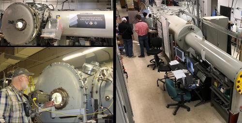
TABLE OF CONTENTS
1.0 GENERAL INFORMATION .......................................................................................................... 1
2.0 INTRODUCTION............................................................................................................................. 2
3.0 SuRE TEST APPARATUS .............................................................................................................. 3
4.0 TYPES OF MATERIALS EVALUATED ....................................................................................... 5
      4.1 Failure Analysis.......................................................................................................................... 5
5.0 USE POLICIES .............................................................................................................................. 5
      5.1 Scheduling .................................................................................................................................. 5
      5.2 Payment Scheduling ................................................................................................................... 6
            5.2.1 Users with a U.S. Government Sponsor ........................................................................ 6
            5.2.2 Users Without a U.S. Government Sponsor ............................................................... 6
            5.2.3 Cancellation Policy ..................................................................................................... 6
      5.3 Test Plan ..................................................................................................................................... 7
      5.4 Test Specimens ........................................................................................................................... 7
            5.4.1 Specimen Shipment ....................................................................................................... 8
            5.4.2 Specimen Evaluation ..................................................................................................... 8
            5.4.3 Specimen Return ............................................................................................................ 8
            5.4.4 Data Submission ............................................................................................................ 8
      5.5 On-Site Visitors .......................................................................................................................... 9
6.0 VELOCITY CONVERSION TABLE ........................................................................................ 10
7.0 ANGLE OF IMPACT DEFINITION ............................................................................................ 12
8.0 SPECIMEN CONFIGURATIONS ................................................................................................ 13
      8.1 Square Specimen: 30, 45, 60, and 90°..................................................................................... 13
      8.2 Disc Specimen: 30, 45, 60, and 90° ........................................................................................ 14
      8.3 Rectangle Specimen: 7 and 16° ................................................................................................ 15

                                                          LIST OF FIGURES
Figure 1: AFRL/UDRI SuRE Test Facility ............................................................................................... 3
Figure 2: SuRE Test Chamber Target Section ........................................................................................... 4
Figure 3: Square Specimen 2 x 2 inches .................................................................................................. 13
Figure 4: Disc Specimen Size 2 x 2 inches .............................................................................................. 14
Figure 5: Rectangle Specimen Size 3 x 10 inches ................................................................................... 15

                                                           LIST OF TABLES
Table 2: Velocity Conversion Table ........................................................................................................ 10
Table 2 continued: Velocity Conversion Table ....................................................................................... 11
AFRL Materials and Manufacturing Directorate Super Sonic Rain Erosion Test Apparatus
1.0 GENERAL INFORMATION
The AFRL Supersonic Rain Erosion Test Facility (herein referred to as “SuRE facility”) is a
government-owned facility operated by the University of Dayton Research Institute (UDRI) to
serve the international aerospace community. Access is provided for both military and commercial
testing. Priority of testing can usually be determined on a first-come, first-serve basis, but on occasion,
this order must be broken for more immediate or emergency evaluations. Failure to comply with the
direction of SuRE facility personnel can result in cancellation of testing. For more information about
the AFRL/UDRI SuRE test apparatus, contact:
Contractor Personnel
AFRL Government Personnel
University of Dayton Research Institute
UDRI Erosion Facilities AFRL Rain Erosion Test Facility
ATTN: Ollie Scott Coatings, Corrosion & Erosion Lab
300 College Park AFRL/RXSS (CCEL)
Dayton, OH 45460-0054 ATTN: Matthew I. Hartshorne
Office: (937) 255-0197 2179 12th St, Building 652 Rm 59
Wright-Patterson AFB, Ohio 45433-7718
(937) 255-4108
Ollie.Scott.ctr@us.af.mil
Ollie.Scott@udri.udayton.edu matthew.hartshorne.1@us.af.mil
Page 1 of 16AFRL Materials and Manufacturing Directorate Super Sonic Rain Erosion Test Apparatus
2.0 INTRODUCTION
The phenomenon known as rain erosion, or the damage to materials caused by the impingement of
raindrops at high speed, has long been a concern to the United States Air Force. The Air Force
Research Laboratory (AFRL) at Wright-Patterson Air Force Base, Ohio, has conducted and sponsored
research on rain erosion resistant materials since 1947. UDRI has been involved in rain erosion
research and erosion-resistant material development since 1964.
In the course of rain erosion research over the years, the rotating/whirling arm apparatus of which
UDRI has participated in the design, development, construction, and calibration has provided the best
laboratory simulation of the environment for evaluating materials and investigating rain erosion
mechanisms at speeds up to 650 mph. However, as aircraft speeds have increased, the need to
conduct rain erosion testing at higher speeds was required. As such, UDRI and AFRL, co -
developed the Super Sonic Rain Erosion (SuRE) test facility that is capable of testing at speeds
between 250 mph and 1750 mph (Mach 2.3).
This highly-specialized apparatus allows scientists to evaluate materials and coatings durability
by directing a spray of water at test specimens, subjecting them to conditions simulating real -
world rain and weather events. Rain drop impact is randomly distributed over the exposed surfaces
of the test specimens. The test duration can be designated in specific increments (e.g., seconds,
minutes or hours) or terminated at the operator’s discretion when erosion damage is observed.
UDRI Erosion specialists can offer expert consultation and recommendations in the development
of test plans to optimize and determine the effects of the high-force spray on the materials and
components.
Page 2 of 16AFRL Materials and Manufacturing Directorate Super Sonic Rain Erosion Test Apparatus
3.0 SURE TEST APPARATUS
The SuRE test apparatus is a unique, one-of a-kind capability that simulates the impact effects of high
speed flight through rain for transonic and supersonic speeds up to Mach 2.3 for a range of water drop
sizes between 1.0 to 2.0 mm. Larger water drop sizes of 3.0 mm can be achieved but rain speeds will
inevitability decrease.
Figure 1 shows the SuRE test apparatus. The SuRE test apparatus utilizes a combination of
technologies to project and distribute water droplets at a variety of velocities to simulate flight
conditions. A computer controlled targeting system is utilized to ensure proper water droplet location
and accuracy. A variable-sized rotating water jet nozzle allows for water droplet size selection as
requested; the rotating feature effectively eliminates potential “hammer-effects” of projected water
droplets. A high-speed camera is utilized to accurately measure/confirm water droplet size and to
measure the speed of the water droplets. High pressure water pumps are utilized to deliver the
necessary deionized water during the test event.
Figure 1: AFRL/UDRI SuRE Test Facility
Page 3 of 16AFRL Materials and Manufacturing Directorate Super Sonic Rain Erosion Test Apparatus
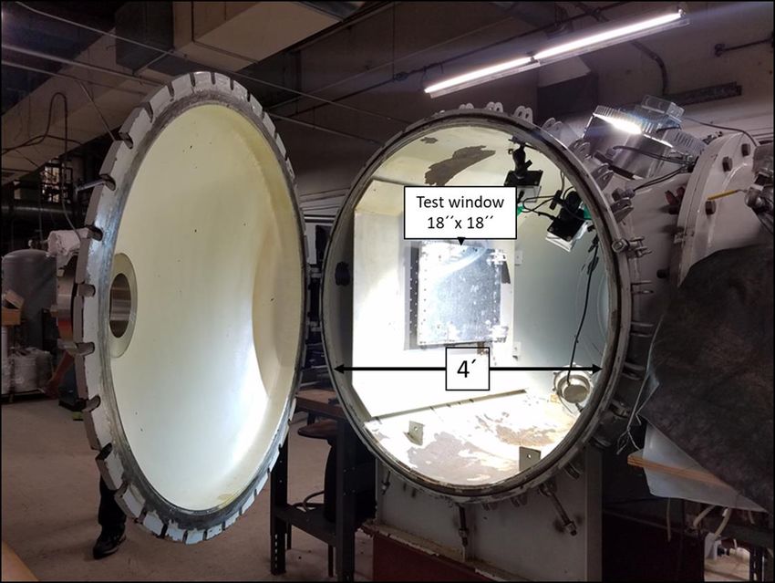
Figure 2: SuRE Test Chamber Target Section
The SuRE test chamber is configured to provide flexibility in the target (sample) size and mounting
arrangement. The target section is a four foot diameter vacuum cylinder. The maximum test window
is 18 x 18 inch (x, y) with capabilities of up to 4-foot (z) for sample projection. This freedom of target
allows for a variety of sample configurations ranging from specimens to full size components. The
entire end of the chamber swings open to accommodate test hardware, test specimens and lighting. A
water drop train travels down a 24-foot flight tube oriented radially to the side of the test chamber.
Those drops strike the test specimen(s) held in test fixtures in an XY raster path.
The typical test exposure is composed of one continuous pass of drops starting from the bottom right
of the target area to the top left of the target area and then back down across the specimen again to
then be parked at the lower right. This motion makes up one full loop that covers the
18 x 18 inch target area in 2 minutes and 6 seconds. Overall sample exposure time can be varied
depending on customer request by iterating the loop exposure to reach the desired total exposure time.
Page 4 of 16AFRL Materials and Manufacturing Directorate Super Sonic Rain Erosion Test Apparatus
4.0 TYPES OF MATERIALS EVALUATED
The following is a list of t ypical materials submitted for rain erosion evaluation.
Composites Coated metals
Coated composites Ceramics
Plastics Honeycomb constructions
Coated plastics Bulk material constructions
Reinforced plastics Glass materials
Metals Optical materials
Radomes Leading Edges
4.1 Failure Analysis
Materials evaluated for rain erosion resistance are normally either bulk type or coated. Damage is
evidenced by material loss (erosion) or coating adhesion failure. Such terms as pitting, cratering,
cracking, material loss or fracture, core-crushing, and delamination are used to describe the
progressive performance of the materials.
5.0 USE POLICIES
5.1 Scheduling
Due to the frequent usage of the SuRE apparatus, prospective users are urged to schedule test
dates well in advance. Scheduling is normally accomplished by calling UDRI at Wright-
Patterson Air Force Base; Office: (937) 255-0197, FAX: (937) 255-0954 or e-mail (see below).
Address US Postal correspondence to:
UDRI Erosion Facilities
ATTN: Ollie Scott
300 College Park
Dayton, OH 45460-0054
Office: (937) 255-0197
Ollie.Scott.ctr@us.af.mil
Ollie.Scott@udri.udayton.edu
Note: Do not use this address to ship samples. See Section 5.4.1 for
sample shipment requirements.
Page 5 of 16AFRL Materials and Manufacturing Directorate Super Sonic Rain Erosion Test Apparatus
IMPORTANT!! SPECIAL ARRANGEMENTS MUST BE MADE FOR DOD
CLASSIFIED TEST SPECIMENS. NOTIFY EROSION FACILITY PERONNEL WHEN
SCHEDULING TEST DATES IF SPECIMENS ARE CLASSIFIED.
5.2 Payment Scheduling
Payment arrangements are substantially different for users with a U.S. Government sponsor than those
without a sponsor. To avoid delays or cancellation of testing, it is recommended that payment
scheduling be arranged as soon as possible after test scheduling.
5.2.1 Users with a U.S. Government Sponsor
Users with a sponsor must contact the Financial Division of the Air Force Research Laboratory
(AFRL/RXFM) at (937) 255-9765 to arrange payment conditions as soon as possible after scheduling
test dates. This is often a time-consuming process, but payment conditions must be arranged before
testing can take place. Testing will be delayed or cancelled if payment conditions are not
arranged.
5.2.2 Users Without a U.S. Government Sponsor
Users without a U.S. Government sponsor operate on a purchase order basis with the University of
Dayton Research Institute (UDRI). The user company must submit the signed “Test Description and
Approval Form” (Appendix A) enclosed in the Formal Proposal from the UDRI office of Contracts
and Grants; [937-229-2919] In addition to the signatures of the UDRI collaborator and an official
from the user company, the form will lastly be signed by AFRL/RXS for completion.
The purpose of this form is to provide mutual assurance of safety, responsibility, and confidentiality
of testing and test results. Suitable time must be allowed to obtain the signatures on this form,
especially with the users’ company. Any discussion or questions regarding this form should be
raised as soon as possible after test scheduling. Testing may be delayed or cancelled if payment
conditions are not arranged at least two weeks prior to the test date(s).
5.2.3 Cancellation Policy
Users who cancel or postpone a scheduled test must contact UDRI at least two weeks prior to the
scheduled test date(s). Users who fail to make timely notification will be charged 20% of the
scheduled test cost. Exceptions to this charge will be made in the event of inclement weather, personal
emergency, or in the event that UDRI can schedule another user in the testing dates that had been
reserved for the original user. In the event that UDRI must cancel testing because payment conditions
have not been arranged or necessary documents have not been received, the same cancellation policy
will apply.
Page 6 of 16AFRL Materials and Manufacturing Directorate Super Sonic Rain Erosion Test Apparatus
5.3 Test Plan
All users must submit a detailed test plan to fully document, guide, and direct specific test needs.
Before scheduling testing, the user should know the number of specimens, geometry, configuration,
maximum run time(s), intermediate inspections (if required), and if the specimens are DOD classified
or unclassified. See Section 8.0 for various specimen and configuration options. See Section 7.0 for
Angle of Impact/Incidence definition.
Prospective users are encouraged to discuss their test plans thoroughly with erosion facility personnel
well before the scheduled test date. In addition to technical matters, guidance can often be provided
regarding the necessary paperwork.
The test plan must include an adequate specimen material description, required velocity and angular
modes, order of testing, and a definition of test duration, e.g., to initial failure, to complete failure
(substrate exposed), length of time, etc. See Section 6.0 for a velocity conversion chart.
The final test plan must be submitted to erosion facility personnel at least 3 days prior to the
scheduled test date to allow sufficient time for review and clarification. The test plan serves as
a basis for the evaluation sheet used by the erosion facility operator at the time of testing.
If the test plan is late or not submitted, the testing may be delayed or cancelled.
Safety Data Sheets (SDS) or other statements of material non-toxicity must be supplied
with the Test Plan.
5.4 Test Specimens
It is the policy of AFRL (Air Force Research Laboratory) to maintain a complete database of all rain
erosion test results from the erosion facility. This data constitutes the history and progress of rain
erosion resistant material development and is accessed only under a strict USAF need basis.
Specimens to be tested must be accompanied by a description sufficient to allow the inclusion of the
material and the results into the database. This description can be generic, but it must include at least
the class of material(s) being evaluated, with some indication as to material treatment, coating
thickness, etc. Specimen description is listed from the top down (face of sample exposed to droplets).
Example:
Polyurethane topcoat, light gray, 0.006” thickness / Polyurethane rain erosion coating, dark gray,
0.020” thickness / Epoxy primer, light green, 0.004” thickness / Chromate-free pretreatment /
Aluminum Airfoil.
Page 7 of 16AFRL Materials and Manufacturing Directorate Super Sonic Rain Erosion Test Apparatus
5.4.1 Specimen Shipment
Specimens must be shipped no less than 7 days in advance of the scheduled test date to allow for
dimensional checking. Because rain erosion test specimens range from the fragile to the rugged,
packaging and shipping should be guided accordingly. Every effort will be made to maintain the
integrity of test specimens, although rain erosion test conditions can compromise this goal. If there is
any concern about specimen configurations, contact erosion facility personnel.
Ship specimens via Fed Ex or UPS to:
ATTN: Ollie Scott, UDRI
AFRL/RXSS (CCEL), Erosion Facilities
2700 D Street, Building 1661, Room C110
Wright-Patterson AFB, OH 45433
IMPORTANT: The address above cannot be used for shipment of classified materials.
IMPORTANT: If test specimens are hand-carried to the erosion facility on the day of
testing and do not fit the testing assembly, the test time will be abbreviated or canceled.
5.4.2 Specimen Evaluation
Due to the design of the SuRE apparatus, specimen evaluation is typically conducted after the test
specimens have been removed from the apparatus. Digital photography is typically used to capture
images of tested specimens. High speed camera footage can be captured during the test event, but
the duration is limited to only a few seconds due to mist and moisture build-up on the SuRE viewing
windows. If required, additional post-test analysis services are available at an additional cost.
5.4.3 Specimen Return
After testing, all specimens and DVD’s containing the files digitally recorded after testing will be
returned via domestic UPS ground service. If a different shipper or expedited shipping service is
required, the user must provide a UPS or FedEx shipping account number. International shipments
are the responsibility of the user.
5.4.4 Data Submission
Following the test and evaluation sequence, an electronic copy (PDF) of the detailed test report is
emailed to the user; a hard copy of the report is available upon request. All test results and all test
specimens are handled on a strict proprietary basis. No endorsement of materials is intended either by
the USAF or UDRI.
Page 8 of 16AFRL Materials and Manufacturing Directorate Super Sonic Rain Erosion Test Apparatus
5.5 On-Site Visitors
Users are welcome to witness the testing of their specimens. Due to facility size and safety restrictions,
no more than three visitors at one time are allowed inside the laboratory. Prior notification is
required and the visitors must contact the government personnel or contractor (see Section 1.0 General
Information) a minimum of 5 business days prior to the test date to gain access to Wright-Patterson
Air Force Base: The visitor access process and requirements change periodically, you will be advised
of the current requirements at the time you contact government personnel.
NOTE: Foreign National visitors may witness the testing of their specimens; however, the visit
access process is different and requires a minimum of 4-8 weeks advance notice.
Page 9 of 16AFRL Materials and Manufacturing Directorate Super Sonic Rain Erosion Test Apparatus
6.0 VELOCITY CONVERSION TABLE
Table 2: Velocity Conversion Table
METER/SEC FT/SEC MPH MACH1 KNOTS KM/HR
100 328 224 0.29 194 360
110 361 246 0.32 214 396
120 394 268 0.35 233 432
130 427 291 0.38 253 468
140 459 313 0.41 272 504
150 492 336 0.44 292 540
160 525 358 0.47 311 576
170 558 380 0.50 330 612
180 591 403 0.53 350 648
190 623 425 0.56 369 684
200 656 447 0.59 389 720
210 689 470 0.62 408 756
220 722 492 0.65 428 792
230 755 514 0.68 447 828
240 787 537 0.71 467 864
250 820 559 0.73 486 900
260 853 582 0.76 505 936
270 886 604 0.79 525 972
280 919 626 0.82 544 1008
290 951 649 0.85 564 1044
300 984 671 0.88 583 1080
310 1017 693 0.91 603 1116
320 1050 716 0.94 622 1152
330 1083 738 0.97 641 1188
340 1115 761 1.00 661 1224
350 1148 783 1.03 680 1260
360 1181 805 1.06 700 1296
370 1214 828 1.09 719 1332
380 1247 850 1.12 739 1368
390 1280 872 1.15 758 1404
400 1312 895 1.18 778 1440
410 1345 917 1.20 797 1476
420 1378 940 1.23 816 1512
430 1411 962 1.26 836 1548
440 1444 984 1.29 855 1584
450 1476 1007 1.32 875 1620
460 1509 1029 1.35 894 1656
470 1542 1051 1.38 914 1692
480 1575 1074 1.41 933 1728
490 1608 1096 1.44 952 1764
500 1640 1118 1.47 972 1800
Page 10 of 16AFRL Materials and Manufacturing Directorate Super Sonic Rain Erosion Test Apparatus
Table 3 continued: Velocity Conversion Table
METER/SEC FT/SEC MPH MACH KNOTS KM/HR
510 1673 1141 1.50 991 1836
520 1706 1163 1.53 1011 1872
530 1739 1186 1.56 1030 1908
540 1772 1208 1.59 1050 1944
550 1804 1230 1.62 1069 1980
560 1837 1253 1.65 1089 2016
570 1870 1275 1.68 1108 2052
580 1903 1297 1.70 1127 2088
590 1936 1320 1.73 1147 2124
600 1969 1342 1.76 1166 2160
610 2001 1365 1.79 1186 2196
620 2034 1387 1.82 1205 2232
630 2067 1409 1.85 1225 2268
640 2100 1432 1.88 1244 2304
650 2133 1454 1.91 1263 2340
660 2165 1476 1.94 1283 2376
670 2198 1499 1.97 1302 2412
680 2231 1521 2.00 1322 2448
690 2264 1543 2.03 1341 2484
700 2297 1566 2.06 1361 2520
710 2329 1588 2.09 1380 2556
720 2362 1611 2.12 1400 2592
730 2395 1633 2.15 1419 2628
740 2428 1655 2.17 1438 2664
750 2461 1678 2.20 1458 2700
760 2493 1700 2.23 1477 2736
770 2526 1722 2.26 1497 2772
780 2559 1745 2.29 1516 2808
790 2592 1767 2.32 1536 2844
1
Mach number based on standard conditions, not actual conditions used for the SuRE facility
Page 11 of 16AFRL Materials and Manufacturing Directorate Super Sonic Rain Erosion Test Apparatus
7.0 ANGLE OF IMPACT DEFINITION
For the SuRE test apparatus, the angle of impact is defined as the angle that the plane of the specimen
surface makes with the plane containing the droplet stream of the SuRE. Therefore, when the specimen
surface is perpendicular to the plane of the droplet stream, the impact angle is 90 degrees. Conversely,
when the specimen surface is parallel to the plane of the droplet stream, the impact angle is 0 degree.
Specimens tested at low/shallow impact angles will exhibit little or no erosion. The lowest impact angle
tested to date on the SuRE is 7 degrees. Specimens tested at the maximum impact angle of 90 degrees
typically exhibit the greatest erosion.
Fixtures can be constructed to accommodate the impact angle needed for testing. Current impact
angles available are 7, 16, 30, 45, 60 and 90 degrees.
Page 12 of 16AFRL Materials and Manufacturing Directorate Super Sonic Rain Erosion Test Apparatus
8.0 SPECIMEN CONFIGURATIONS
8.1 Square Specimen: 30, 45, 60, and 90°
Figure 3: Square Specimen 2 x 2 inches
All dimensions in inches
The effective specimen exposure area is 1.5 x 1.5 inches
Maximum specimen thickness is 1.0 inch
Specimen holder can accommodate 8 test specimens
Page 13 of 16AFRL Materials and Manufacturing Directorate Super Sonic Rain Erosion Test Apparatus
8.2 Disc Specimen: 30, 45, 60, and 90°
Figure 4: Disc Specimen Size 2 x 2 inches
All dimensions in inches
The effective specimen exposure area is 1.5 x 1.5 inches
Maximum specimen thickness is 1.0 inch
Specimen holder can accommodate 8 test specimen
Page 14 of 16AFRL Materials and Manufacturing Directorate Super Sonic Rain Erosion Test Apparatus
8.3 Rectangle Specimen: 7 and 16°
Figure 5: Rectangle Specimen Size 3 x 10 inches
All dimensions in inches
Maximum specimen thickness of 1.25 inches
Specimens must be mounted on a metal plate; the plate must have 2 standard screw
holes for securing the specimen in the holder
Pocket depth of the specimen holder is 1.5 inches
Specimen holder screw holes are 2.5 inches from the top (short edge (3 inches)) and
bottom edges and are 1.5 inches from the long edge.
Specimen holder can accommodate 8 test specimen
Shims are made available for height adjustment of the sample in the pocket
Page 15 of 16AFRL Materials and Manufacturing Directorate Super Sonic Rain Erosion Test Apparatus
In the event standard specimen configurations and fixtures offered by AFRL/UDRI erosion facility
do not meet the requirements of the user, it is possible to have custom specimen configuration
fixtures designed and fabricated. The erosion facility personnel will work closely with the user in
developing safe and effective specimen configuration tooling.
Materials used to manufacture specimen fixtures depend on the expected useful testing lifetime.
Fixtures are typically made from stainless steel, titanium alloy, or 2XXX or 7XXX series tempered
aluminum or combinations of these.
End of Guide
Page 16 of 16You can also read