All workers and road users go home safe every day - New Zealand guide to temporary traffic management The Toolbox
←
→
Page content transcription
If your browser does not render page correctly, please read the page content below
All workers and road users go
 home safe every day

New Zealand guide to temporary traffic
management
The Toolbox
7 March 2022
Draft for feedback

Contents
 1. TTM Toolbox – What TTM Engineering includes .............................................................. 3
 1.1. Introduction ..................................................................................................................... 3
 1.2. Design ............................................................................................................................. 3
 1.2.1. Governing TTM design principles ................................................................................... 3
 1.2.3. Geometric design ............................................................................................................ 4
 1.3. Equipment ..................................................................................................................... 10
 1.4. Specialist projects ......................................................................................................... 22

Waka Kotahi NZ Transport Agency New Zealand guide to temporary traffic management - 2
1. TTM Toolbox – What TTM Engineering includes
1.1. Introduction
1.1.1. Structure
The toolbox has two key components:
 • Design principles – the design section covers all engineering principles used to ensure the
 geometry is appropriate and workers or event participants are kept safe by giving the public the
 best chance to navigate the site safely.
 • Equipment for TTM – the equipment section covers all equipment available for use on TTM sites.
 This includes both material and use specifications.

1.1.2. References and why we have them
This section of the NZGTTM includes references to external documents because:
 • most importantly, TTM is simply permanent road design delivered temporarily so there is no need
 to develop TTM specific material.
 • by referencing permanent design material, it’s easier for a TTM planner to find what they need for
 complex sites, for example major capital works projects with temporary road alignments
 • it keeps the NZGTTM short and easy to read
 • design guidance is kept up to date.

1.2. Design
1.2.1. Governing TTM design principles
Background
Changing the permanent transport system influences human behaviour. Workers on the transport system
are at risk of harm from hazards – buried services, weather, noise, vibration, dust etc, but the NZGTTM
focuses on the interface between the activity and traffic. The users of the transport system are also at risk
of harm from the worksite – change in surface, geometry, roadside hazards such as trenches, plant, and
partially completed guardrails, products such as bitumen and chemicals. The focus is to aid them to detect
and navigate the site safely.
Both the public and workers are humans – unlike water in a pipe, where every molecule behaves the
same for a given pressure and temperature, humans all behave differently. Humans, the workers and
users of the public transport system, all have different:
 • Levels of comprehension or detection and reaction
 “I didn’t understand what the sign meant”,
 “I didn’t know I wasn’t allowed in the exclusion zone
 “What is an exclusion zone?”
 • Risk tolerance
 “I’m very nervous, I don’t know how to drive on gravel.”
 “It’s only a little snow, I have a 4wd, she’ll be right.”
 “I can chuck some mix in the pothole in the gaps in traffic, stand back.”
 • Understanding of their rights of access to the transport system
 “You can’t stop me.”
 “Those are my car parks.”
 “I demand to drive down this closed street.”

Waka Kotahi NZ Transport Agency New Zealand guide to temporary traffic management - 3
“I have an over dimension permit, get your worksite out of my way”
 “I have an approved TMP, you cannot come through here.”
 • Motivators/personal stress
 “My business will fold if I can’t deliver this product/get to this job today.”
 “My child is waiting for me at the school gate and very stressed.”
 “No worries I’ll go another way”
 “I’ve got to get this job done within the next 5 mins or we don’t meet contract KPI.”
Providing for all the human needs for those using the transport system is challenging, but HSWA requires
that safety is prioritised above other risks.
From the seven guiding principles of Road to Zero, New Zealand’s road safety strategy 2020-2030, the
following are key to TTM:
 • We promote good choices but plan for mistakes.
 • We design for human vulnerability.
 • We make safety a critical decision-making priority.

1.2.2. Governing design principles
Communication
All actions you take must communicate changes in transport system operating conditions to drivers,
cyclists, pedestrians, public transport users so they know what is expected of them and can safety use the
changed transport system.
In designing a site layout this means that we must provide clear:
Advanced warning – make sure the public know there is a change to the road operating conditions
ahead. This is typically the fact there is a site ahead and the type of site.
Guidance – make sure the public know how to navigate the site from advanced warning to return to
normal.
Protection – ensure protection from site hazards for the public or protection from traffic for workers.
Return to normal – make sure the public know they have passed the site and permanent road operating
conditions and rules apply.

 These are the most important principles for design of a site. If anything within the design section of
 the NZGTTM contradicts these principles, the Governing Design Principles take precedence.

An example of this is advanced warning sign spacing. Advanced warning must always be provided. If
something changes such as queue lengths increase, the advanced warning signs must be relocated. This
may happen when traffic flows increase beyond the capacity of a manual traffic control system.

1.2.3. Geometric design
Geometric design makes sure the shape of a road is appropriate for the way it’s being used. It’s based on
human factors such as detection, decision making and reaction times, as well as physics such as braking
forces (energy and friction), and cornering forces (radial acceleration and friction). Dimensions used are
usually time (seconds) and distance (meters).
Horizontal and vertical geometry
The traditional approach to permanent design is to consider both horizontal and vertical geometry and
combine them into one complete design.
Horizontal geometric design is designing the straights, curves, cross-section widths and crossfall of roads.
It deals with time and distance in 2 dimensions – along the road and across the road.
Vertical geometric design is designing the gradients and crest & sag curves of roads. It deals with time
and distance in 1 dimension – height or depth.

Waka Kotahi NZ Transport Agency New Zealand guide to temporary traffic management - 4
Transport system users Design decisions must consider all transport system users and make provision for them if they use the road network affected by the works or activity. Common transport system users include: • Blind and low vision users • Mobility impaired • Pedestrians • Cyclists • Public Transport • Light Vehicles • Heavy Vehicles • Over-dimension and over-mass vehicles Providing for these transport users, or any others identified, can be done through creating separated facilities, combined facilities, or excluding certain users. Regardless of the approach, all user types identified must be considered and a decision made. It is unacceptable to ignore any user group. Detailed design Below is a list of references to assist with design of TTM for sites. Traffic Control Devices Manual part 1 2010 – https://www.nzta.govt.nz/resources/traffic-control- devices-manual/index.html Austroads Guide to Road Design part 3 2021 - https://austroads.com.au/safety-and-design/road- design/guide-to-road-design Waka Kotahi NZ Transport Agency Pedestrian Network Guidance (2021) https://www.nzta.govt.nz/walking-cycling-and-public-transport/walking/walking-standards-and- guidelines/pedestrian-network-guidance/ Public transport design guidance – https://www.nzta.govt.nz/walking-cycling-and-public- transport/public-transport/public-transport-design-guidance/. Specific guidance is provided for temporary bus stops - https://www.nzta.govt.nz/assets/resources/code-temp-traffic- management/docs/Section-I-13-bus-stops-copttm-4th-ed-may2016.pdf Cycling network design guidance - https://nzta.govt.nz/walking-cycling-and-public- transport/cycling/cycling-standards-and-guidance/cycling-network-guidance/designing-a-cycle- facility/#design-guidance Specific references for various design elements are provided below. Advanced warning Providing enough time for the public to identify they need to follow a detour Visibility of devices due to both corners (horizontal geometry) and crests & dips (vertical geometry) – Traffic Control Devices Manual part 1, section 7.3 Location. Guidance Providing enough time for the public to identify the detour route including relocation to the correct lanes. • Visibility of devices due to both corners (horizontal geometry) and crests & dips (vertical geometry) –Traffic Control Devices Manual part 1, section 7.3 Location. • Advanced warning time (distance) should be longer than any traffic queue – section 5.2.4 for more information on working out queue lengths. • All Horizontal & Vertical design – Austroads Guide to Road Design part 3 (2020) and Waka Kotahi NZ Transport Agency Supplement TM-2501. This covers, lateral shifts, curves, crossfall, and warp rates. Note temporary roads must have their geometry checked. Lane dimensions to ensure all users have sufficient space. • Traffic lane widths (horizontal geometry) – Austroads Guide to Road Design part 3 (2020), section 4.2.4 Waka Kotahi NZ Transport Agency New Zealand guide to temporary traffic management - 5
• Bus lane widths (horizontal geometry) – Austroads Guide to Road Design part 3 (2020), section
 4.10.2
 • Bus stops – Waka Kotahi public transport design guidance
 • Cycle lane widths (horizontal geometry) – Waka Kotahi cycling network design guidance
 • Cyclists at intersections – Waka Kotahi cycling network design guidance
 • Footpath widths (horizontal geometry) – Waka Kotahi Pedestrian Network Guidance, Design
 • Pedestrians at intersections – Waka Kotahi Pedestrian Network Guidance, Design
Safe and appropriate speed limits to ensure safety and compliance
Speed limit selection is subject to human body tolerances, vehicle technology and both horizontal and
vertical geometry. There are two methods to determine an appropriate speed for a worksite:
 • Activity based – the human body can only withstand so much force before injuries become fatal.
 So what a human is doing guides the selection of an appropriate speed limit. This is the best way
 choose a speed limit. The following table shows target speeds for different activities. These
 speeds had been taken from research by Wramborg, P. (2005) and later reviews.

 Activity – sites with Target Safe System speed
 Possible crashes between vehicles and 30 km/h
 • workers on foot
 • pedestrians
 • cyclists
 • any other person not protected by a
 vehicle
 Possible side-on crashes between vehicles 50 km/h
 Possible head on crashes between vehicles 70 km/h

 • Environment based – A secondary way to work out the best speed limit is to consider the road
 environment. In this situation the geometry (vertical and horizonal curves) and surfacing.
Protection
Ensuring that those who do not observe the controls do not crash into queued traffic, people, or plant on
the site
 • Safe stopping distances (subject to both horizontal and vertical geometry) – Austroads Guide to
 Road Design part 3 (2020), section 5.3
 • Roadside safety space (for risk mitigation, recovery or stopping safely when lose control) –
 Austroads Guide to Road Design part 6 (2020), section 3.5
 • Shy lines (the closet to an object that a driver feels comfortable driving) – Austroads Guide to
 Road Design part 6 (2020), table 5.4
Return to normal
Providing enough time for the public to know they have completed the detour and permanent road
operating conditions resume
 • Visibility of devices due to both bends (horizontal geometry) and crests & dips (vertical geometry)
 – Traffic Control Devices Manual part 1, section 7.3 Location.
Go to austroads.com.au/publications/road-design/agrd-set for the full Austroads Guide to Road Design
Common horizontal and vertical geometry information
As many of the sites TTM is prepared for are simple sites, the following table is a summary of common
geometric design information from the references above:

Waka Kotahi NZ Transport Agency New Zealand guide to temporary traffic management - 6
PLACEHOLDER – this will be populated in the final document.
 Common Geometrid Design Parameter Value
 Speed 30 km/h 50 km/h 70 km/h 100 k/h
 Sight Distance
 Taper length
 Stopping Distance
 Curve radius (3% positive crossfall)
 Other dimensions

1.2.4. Traffic engineering
Traffic engineering has been broken into two sections – Safety and Delay.
Safety covers permanent intersection and mid-block design and is included to assist in the choice of
alternative routes and their risks.
Delay information allows you to work out queue lengths as well as appropriate sign spacings. It’s also
useful for working out the size of delay to the public and the possible choices they might make. For
example, long delays can lead to unsafe choices such as U-turns, ignoring stop/go controls or running
through traffic lights.
Safety
The transport system is made up of two main parts – intersections and links.
Intersections
Basically, the fewer overlapping turning paths and the lower the speed, the safer an intersection is. In
order of least safe to most safe, intersection forms are:
 1. Uncontrolled intersections – no stop or give way sign
 2. Give way controlled intersection
 3. Stop controlled intersection
 4. Traffic signals
 5. Roundabout
 6. Interchange
Additional information
 a) Higher speed at an intersection = higher risk from higher probability and higher consequence
 b) More approaches = more risk from higher probability. Crossroads (4-way) intersections are more
 dangerous than T intersections (3-way). Five- or six-way intersections are more dangerous. This
 is because there is a higher number of conflict points, that is, points where paths of vehicles
 overlap. At a 4-way intersection there are 12 conflict points and only 3 conflict points at a T
 intersection.
 c) Some crash types are higher consequence. Glancing crashes are generally safer than T-bone
 crashes. Roundabout crashes are usually glancing crashes rather than T bone because of the
 curved travel path. Interchanges, while high speed, are low angle glancing crashes.
 d) Y intersections are much higher risk than T intersections. This is because drivers must look over
 their shoulder and have trouble judging the speed of an approaching vehicle.
Property entranceways and site accesses are also intersections and must be considered when doing risk
assessments.
Links
A link, also known as mid-block links, is a road or path between intersections. The safety of a link is
dependent on the cross section, speed, and volume of traffic.
 • Cross section

Waka Kotahi NZ Transport Agency New Zealand guide to temporary traffic management - 7
o Where the cross section has many hazards such as poles, drainage ditches and
 headwalls, risk increases through higher probability of an out-of-control vehicle coming to
 an abrupt stop.
 o Where the sealed pavement is narrow, risk increases. This is because there is less space
 and time for drivers to correct steering errors, for example, an unsealed shoulder or no
 shoulder. A wide sealed shoulder is safer than an unsealed one, and an unsealed
 shoulder is safer than no shoulder.
 o Where there is no protection, such as guard rails, from roadside hazards or oncoming
 vehicle, the risk of a severe crash increases.
 o Where there is something on the surface that reduces skid resistance the risk of a loss of
 control crash increases. Examples include, gravel road, sealing chip, ice, snow, rain,
 flooding, mud from slips and soil tracked onto the road.
 o Where permanent delineation is poor or there is none, the risk of a run-off-road crash
 increases, especially in low light conditions. Examples include, no line marking, no raised
 reflective pavement markers, or no edge marker posts.
 • Speed
 o Speed increases risk of both the probability and consequence on all roads in every
 situation. A higher speed means less time for drivers to correct errors and increases
 severity when something does go wrong.
 • Volume of traffic
 o At high speeds, high volumes of traffic increase the probability of a crash. However, when
 congestion occurs, for example high volumes at low speeds, the volume no longer
 matters as low speed greatly reduces crash severity.
The information above will help with risk assessments, decisions around identifying the appropriate
fundamental TTM controls and the detailed design of the TMP for the site.
The following Waka Kotahi documents for more information on safety and identifying and assessing risk
for rural roads and intersections.
 • High Risk Rural Roads Guide - nzta.govt.nz/resources/high-risk-rural-roads-guide/
 • High Risk Intersections Guide - nzta.govt.nz/resources/high-risk-intersections-guide/
Delays
Delay information will help with both risk assessment and design. Longer delays can increase the risk of
drivers making poor choices due to frustration. Delays, specifically queue lengths inform detailed design of
the TMP for the site.
Delays are also calculated for intersections and links separately, but there are several formulas to aid in
both scenarios.
 • Flow and speed are related through traffic density. As flow increases, speed slowly decreases,
 until capacity is reached – maximum density. At maximum density this is also maximum flow, any
 increase in flow will result in slowing of speed. This is called flow breakdown.
 • Capacity of any lane is 1800 vehicles per hour (vph) because of the two second rule. The shortest
 distance between any two vehicles at maximum density is two seconds. As an hour is 3600
 seconds, the unimpeded maximum flow is:

 3600 ℎ
 ℎ
 = 1800 ℎ
 2
 ℎ
 • The 1800 vehicle per hour per lane formula is affected by the following:

Waka Kotahi NZ Transport Agency New Zealand guide to temporary traffic management - 8
o 30 kph temporary speed limit has a capacity of 1500 vehicles per hour because the
 bumpers of two cars are more than 2 seconds apart at 30 kph. If the front bumpers of two
 cars are two seconds apart, the following car would crash into the car in front.
 o A merge at any speed has a capacity of 1300 vehicles per hour because of the varying
 choices of drivers when merging – not all drivers merge like a zip.
 o Intersections lower capacity by reducing the time within an hour that movement can be
 made. For example, a traffic signal provides 65% of each cycle to the main road and 35%
 to the side road, so the capacity on each road is a percentage of the 1800 vehicles per
 hour. Main road capacity is.
 ℎ ℎ
 1800 0.65% = 1170
 ℎ ℎ
 This is a great way to do a basic analysis of an intersection, but when there are right hand
 turn phases, uncontrolled movements, and random arrival of opposing traffic, it quickly
 gets much more complicated.
 o Stop/go or portable traffic signals are the same as traffic signals, only part of the hour is
 available to any one movement, so capacity is less than 1800 vehicles per hour. Stop/go
 is more complicated as the time it takes for the last car to enter and exit the site must also
 be counted. At 30kph or 8.34 meters per second, it can take 18 seconds for a car to travel
 through a 150m site.
 • Queuing occurs when traffic is stopped or when demand is higher than the capacity.
 o For stopped traffic such as stop/go, traffic signals, the queue length is determined by
 assessing the flow rate and the time of the stop. For example, if the flow rate is 1000 vph
 and traffic is stopped for 40 seconds this leads to a queue length of:
 ℎ
 1000
 40 ℎ
 8 ℎ = 88.9
 3600
 ℎ
 o When the traffic volume approaching a location is higher than the capacity, queueing will
 happen. For example, if there are 1500 vph approaching a merge with 1300 vph capacity,
 200 vehicles will queue per hour.
 o Queues grow over time. Using the merging example, if a demand is 1500 vph for two
 hours, there will be 200 vehicles queued at the end of the first hour and 400 vehicles
 queued at the end of the second hour.
 o Each vehicle takes up around 8m of space on average – some vehicles are shorter and
 others such as trucks are much longer. So, 400 queued vehicles will create a queue of
 around 3,200m (3.2km).
This a very simplistic introduction to traffic engineering. If you need more help, the following options are
available:
 • CTOC Transport Efficiency and Impact Guide – available from CCC Transport page
 https://ccc.govt.nz/assets/Documents/Transport/CTOC/1804-CTOC-Transport-Efficiency-and-
 Impact-Guide.pdf . Note this was written during the rebuild of Christchurch and at a time when
 journey efficiency was as important as safety. This is no longer correct – safety has priority.
 • Talk to a professional traffic engineer. All major and many smaller engineering consultancies have
 this resource. The key is knowing when professional expertise is required and when it’s not. This
 skill set would be valuable to any major project such as construction of a new road or work on an
 arterial or state highway in a city. If in doubt, ask.

Waka Kotahi NZ Transport Agency New Zealand guide to temporary traffic management - 9
1.3. Equipment
1.3.1. Static equipment
Signs
Sign manufacture specification
All temporary works signs and any relevant regulatory signs used for TTM must comply with the Land
Transport Rule: Traffic Control Devices 2004 (TCD Rule). The rule legally defines signs and their design –
colours, size, symbols, text.
nzta.govt.nz/resources/rules/traffic-control-devices-index/
Other easier to read information is the Traffic Control Devices Manual (TCD Manual).
nzta.govt.nz/resources/traffic-control-devices-manual/ or the Traffic Sign Specifications (TSS)
nzta.govt.nz/resources/traffic-control-devices-manual/sign-specifications/
Note the TSS hasn’t got all the signs legally defined in the TCD manual and rule, so look at these if a sign
option is missing from TSS.
Colours, dimensions, names, and symbols must comply with the requirements of the TCD rule.
Materials for signs, are covered in the following documents:
 • Waka Kotahi P24:2020 Specification for Permanent Traffic Signs. nzta.govt.nz/resources/traffic-
 signs-perf-based-specs/. This document covers permanent signs but the backing board (sign
 substrate) and sign face materials sections apply. The following sections are highlighted –
 o Sign manufacturer identification
 o Sign manufacture
 o Retroreflective sheeting – see M/25 nzta.govt.nz/resources/retroflective-sheeting/
 o Aluminium substrate sign systems
 o Additional sections may apply for example support systems and foundations.
 • Approved retroreflective materials – listed in the New Zealand Gazette. The most current
 reference is Notice Number 2021-au4552. This is regularly updated so always check the most
 current version, when this notice is revoked an update link is provided.
Some signs used currently won’t comply with dimensions, fonts, symbols, or layout. These signs can
continue to be used but they should be phased out as quickly as possible. All new signs purchased for
TTM must be consistent with the TCD rule.
Alternative signs
The words and symbols on signs specified in the TCD and TSS are designed to keep consistency across
the country. It is best to use these signs as the public are used to them and will respond consistently.
Sometimes alternative signs are needed. There are three options for alternative signs:
 • General temporary warning – The Land Transport Rule (Traffic Control Devices) 2004 first
 schedule makes allowance for signs with only words on an orange or white background. The
 TCD, W7-8 General temporary warning has size, colour, text size requirements. Symbols are not
 allowed, and it can’t be used as a supplementary sign.
 • General temporary warning – variable message – The Land Transport Rule (Traffic Control
 Devices) 2004 first schedule makes allowance for variable message signs. See TCD, W7-8.1
 General temporary warning – variable message.
 • Advertising Signs – The Traffic Control Devices Manual part 3 section 6 contains information on
 advertising signs for information on sign message and letter size.
Non-standard traffic sign

Waka Kotahi NZ Transport Agency New Zealand guide to temporary traffic management - 10
The Land Transport Rule (Traffic Control Devices) 2004 first schedule makes allowance for signs with
words only on an orange or white background. Refer TCD, W7-8 General temporary warning Drivers.
If you want to have a non-standard sign included in the TCD and TSS, send a detailed request to:
tcd@nzta.govt.nz
Sign Stands
Sign stands must:
 • be stable enough to remain upright during all reasonably expected conditions – wind, air
 turbulence, ground conditions. The main task of a sign is to clearly inform the public and they must
 be upright to do this task.
 • not be a hazard to road users, including cyclists, pedestrians, or other vulnerable road users when
 in use, either upright or if it falls over.
Generally, signs are installed on portable stands. For long-term sites, more structurally sound options are
encouraged so they stay upright with little maintenance. Remember that sending staff to make sure signs
are upright exposes them to risk. Also, be careful with ground planted stands and make sure there isn’t
any conflict with underground services.
When using a portable stand, the sign and stand must:
 • lie flat if it falls over, with no part more than 150mm above the ground.
 • be secured. Any method can be used, as long as it doesn’t present a hazard to road users when
 upright or if it falls over. Weighting devices must not become a projectile if they are struck and be
 within the lifting capability of a single person – WorkSafe Manual Handling guidance
 worksafe.govt.nz/topic-and-industry/manual-handling.
 • secure the sign firmly in a way that doesn’t cover the sign’s message.
Sign use
Signs must:
 • not present a hazard to all road users when installed or stored on the road/roadside. This includes
 both longitudinal and lateral positioning
 o Space must be always provided for all vehicle types, cyclists, pedestrians, or other
 vulnerable road users should not have to travel in live traffic lanes to get around signs.
 o If members of the public need to go around a sign, the path must be clear of risk, for
 example, ramped vertical steps or plated trenches.
 • be installed so they display messaging to the public.
 • be in good condition.
Vertical delineators
There is no national or international standard for vertical delineator manufacture, so this section contains
the Aotearoa New Zealand detailed manufacturer specification.
Vertical delineators manufacture specifications
Delineation devices such as cones, tubular delineators, and barrels for TTM use, must be designed and
manufactured to meet the requirements of this specification.
Manufacturers must be able to show the colour and luminance compliance and photometric performance
compliance of the retroreflective material with a recognised, independent testing laboratory's certificate of
compliance. The certificate may remain valid for a maximum of 36 months and must note the delineator
type tested. Manufacturers are expected to make sure colour and luminance remain within specification. A
new certificate of compliance must be obtained within 36 months by submitting the device for re-testing.
To show compliance with this specification, the letters TTMC MM/YY (month and year) of readable size
must be embossed or otherwise permanently marked on the upper base of the delineator.

Waka Kotahi NZ Transport Agency New Zealand guide to temporary traffic management - 11
Delineators compliant to the previous TTM specifications (CoPTTM) purchased before the date of this
specification being published, may remain in use until they are no longer fit for purpose.
Colour
All vertical delineation devices must be manufactured as fluorescent orange with:
 a. chromaticity coordinates as in table 2.6 of AS/NZS1906.1:2017,
 b. minimum luminance factor as in table 2.9 of AS/NZS 1906.1:2017.
The internal colour and the underside of the base of cones, tubular delineators and barrels must also be
white or orange, so the device remains visible if knocked over – black is not permitted. Orange must be
compliant to a. above but doesn’t need to be fluorescent. A commercial paint chart white can be used to
determine if the white is suitable.
Colour dispensation is allowed for the underside of a cone base that is manufactured using a minimum of
30% of recycled cone material. In such instances colour must comply with the specification in AS/NZS
1906.4 for orange red.
Retro-reflectivity
Delineation devices must be manufactured with white or silver retroreflective bands that:
 • meets approved retroreflective sheeting requirements – Waka Kotahi M/25
 https://www.nzta.govt.nz/resources/retroflective-sheeting/
 • conform to the required band width and positioning as below on the device and is attached
 securely to the vertical delineator.
Dimensions
Vertical delineators used for delineation purposes must:
 • be a minimum height of 900mm
 • be a maximum unballasted weight of 7kg
 • have a minimum viewing area of 67,500mm2 (eg 75mm wide x 900mm) tall when viewed from the
 direction of travel. Note a cone shows a much larger area than this despite being narrower at the
 top.
 • have a base shape that prevents rolling when knocked over.
 • be made of a material that will return to shape when struck.
 • be stable when installed
 • have retroreflective bands installed
 o Lower band – between 100mm and 110mm wide and 400mm ± 5mm from the ground
 o Upper band – between 150mm and 165mm wide and 650mm ± 5mm from the ground
 • not have a company logo must bigger than 5000mm2 (eg 50mm x 100mm) with the top of the logo
 no higher than 200mm ± 20mm from the ground.
 • be stable enough to remain upright in most conditions
 • be made of a flexible polymer or similar material
An exception to this is when delineators used to delineate and protect wet road markings. These
delineators are to meet all the requirements above with the following exceptions:
 • Height – a minimum height of 450mm.
 • Retroreflective band – a single band 250mm ± 5mm from the ground that is between 100mm and
 110mm wide
 • These are not to be used as delineation for any other purpose.

Waka Kotahi NZ Transport Agency New Zealand guide to temporary traffic management - 12
Using vertical delineators
Vertical delineators must provide clear guidance to road users, so they understand what is required of
when there are changes to the operating conditions of the road. This is known as self-explaining roads.
This includes:
 • clear delineation through clean lines of cones so it does not look like a confusing jumble
 • spaced so there’s no confusion on the required action, for example follow a curve, lateral shift, or
 stay in a lane that’s not the usual lane (contra-flow). You may need to change the spacing
 between cones if it looks like drivers are unclear on what they are being asked to do or not do.
 • the right vertical delineator for the duration of the project. For long term sites it may be more
 appropriate to use vertical delineators that are fixed to the road surface, requiring less
 maintenance to provide clear and clean delineation.
Safety fencing
Safety fencing manufacture specifications
Safety fences must comply with the Building Act 2004.
In summary, a safety fence must keep children under the age of 6 years from being able to cross it. The
main design criteria are:
 • the fence must be 1.2m from the ground or any object or projection on the outside of the fence
 • the space between the bottom of the fence and ground level must not be more than 100 mm
 • the spacing between adjacent vertical pales, panels, or other posts, must not be more than 100
 mm at any point
 • any perforated material, netting, or mesh used, must not have an opening more than 50 mm
For TTM application the panels shall
 • be interlocking
 • be fluorescent orange or alternating white and fluorescent orange in colour
 • remain upright and stable under all expected worksite conditions
 • be free of sharp objects
 • have retroreflective delineators fitted
 o as per vertical delineators that is 75mm wide with two retro reflective bands at the
 specified dimensions fitted, or
 o 200mm x 150mm retroreflective panels for use with temporary road safety barriers must
 be fitted to the retroreflective delineators.
Using safety fencing
Fencing shall be installed in way that keeps children under the age of 6 years from being able to climb
over, crawl under or pass around the fence.
For night-time use, amber flashing beacons may be fitted.
Plastic water-filled fences and barriers may be used as a safety fence under the following conditions:
 • The design and installation must comply with the design requirements for safety fences listed
 above.
 • Must only be used in less than 65km/h posted speed environments.
For greater than 65km/h posted speed environments, accepted road safety barrier systems must be used
in line with the barrier design specifications.

Waka Kotahi NZ Transport Agency New Zealand guide to temporary traffic management - 13
Cone bars
There is no national or international standard for cone bar manufacture, so this section contains the
Aotearoa New Zealand detailed manufacturer specification.
Cone bar manufacture specifications
Cone bars must:
 • be a maximum of 7kg
 • be a Maximum length of 2.2m
 • be between 35mm and 100mm diameter
 • be alternating black and orange or black and yellow stripes. Stripes must be a minimum length of
 150mm up to a maximum of 300mm.
 • be the orange or yellow approved retroreflective sheeting that meets the requirements of Waka
 Kotahi M/25 https://www.nzta.govt.nz/resources/retroflective-sheeting/
 • be manufactured from a non-splintering frangible type material
 • have a ring on either end to go over a cone.
Using cone bars
Cone bars may be used to channel pedestrians on worksites where workers are present. They must not
be used to replace a safety fence.
Barricades
There is no national or international standard for barricade manufacture, so this section contains a
detailed manufacturer specification and use guidance.
Barricade manufacture specifications
Barricades must:
 • have sight boards with a vertical dimension of 150mm to 300mm and horizontal lengths of 600mm
 to 1800mm
 • the sight board must be mounted with the centre line of the uppermost rail 900mm, ± 120mm
 tolerance, above the ground surface
 • a fluorescent orange colour that conforms to AS/NZS 1906.1
 • sight boards must have alternating 100–150mm-wide white and fluorescent orange retroreflective
 stripes that slope at 45 degrees to the vertical, with the lowest point of the stripes towards the live
 lane. For approved retroreflective sheeting see Waka Kotahi M/25
 nzta.govt.nz/resources/retroflective-sheeting/
Using barricades
Barricades may be used to clearly show a road is closed.
Temporary road safety barriers
Temporary road safety barriers manufacture specifications
The Waka Kotahi M23: Specification and guidelines for road safety hardware covers the requirements for
permanent and temporary road safety barrier systems for use on the Aotearoa New Zealand network
nzta.govt.nz/resources/road-safety-barrier-systems/.
All temporary road safety barrier systems used must be approved and published in the M23 specification.
Any road safety barrier hardware not listed must be submitted to Waka Kotahi Programme and Standards
Lead Safety Advisor for review and acceptance M23.Queries@nzta.govt.nz
Retroreflective markers

Waka Kotahi NZ Transport Agency New Zealand guide to temporary traffic management - 14
Barrier systems must be fitted with reflective markers (chevrons) if the barriers used to channel traffic. The
chevron must be a retroreflective orange arrowhead on a rectangular black background 150mm x 200mm.
The chevron must point to the side of the barrier that traffic is to pass. For approved retroreflective
sheeting see Waka Kotahi (NZ Transport Agency) M/25 https://www.nzta.govt.nz/resources/retroflective-
sheeting/
Visibility screens
Visibility screens must:
 • be opaque, for example, shade cloth, corrugated plastic or corriboard or other similar frangible
 materials). Do not use rigid materials unless it can be demonstrated by crash testing or similar
 means that it won’t cause injury when hit.
 • provide a continuous screen a minimum of 2m in height above the pavement
 • be able to withstand a crash when attached to a temporary barrier or free standing
 • have a smooth and visually uncluttered surface of uniform colour. The same surface and colour
 must be used for the whole system.
The frames supporting visibility screens must not be a hazard to workers, pedestrians, or vehicle
occupants when hit. All joints must be welded or similarly connected. Mechanical fixings such as pipe
clamps or bolted joints must not be used. All tube bends or frame corners must have a radius of more than
100mm.
Visibility screens and their supporting structures must be able to withstand all environmental impacts
including the wind created by passing vehicles. The screens must not move out of line or move in a way
that distracts motorists.
Advertising or corporate marketing must not be applied to a visibility screen.
Using temporary road safety barriers
Temporary road safety barrier hardware must meet or exceed the required barrier system performance
test level required for the permanent speed limit of the road:
 • Permanent speed 50km/h or less – test level 1 or higher
 • Permanent speed 50-70km/h – test level 2 or higher
 • Permanent speed 70km/h or greater – test level 3
All products installed must follow the system manufacturers or system supplier’s installation guidelines,
including approved jointing and anchoring systems, and end treatments. All parts must comply with the
drawings and specifications.
Temporary road safety barrier systems are a physical separation between traffic and a worksite. They
redirect a crashing vehicle and minimise occupant injury, while also protecting people and area behind the
barrier.
Temporary road safety barrier systems can be used:
 • where workers need to be shielded from traffic
 • when traffic needs to be shielded from worksite hazards such as deep excavations
 • when there are no other options to safely channel vehicle and pedestrian movements.
When designing temporary barriers, you must consider:
 • shy lines – the space between the live lane and the barriers
 • deflection space – space that a barrier deflects away from the traffic lane when struck by a vehicle
 • end treatment options –
 o an approved end treatment such as a crash cushion
 o flaring of barrier system so the end cannot be struck

Waka Kotahi NZ Transport Agency New Zealand guide to temporary traffic management - 15
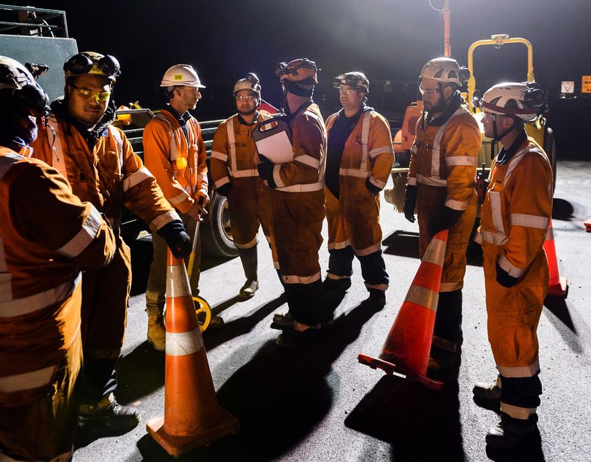
o starting the system behind the end of a permanent system.
 • keeping out of control vehicles from entering the workspace
 • barrier length – follow manufacturer’s specifications.
The pros and cons of each design decision must be risk assessed based on the challenges of each site.
For example – vehicles or people should not be in the deflection zone of a barrier, but if a site does not
allow for this and only vehicles are in the deflection zone, a barrier will still lower the risks more than not
having one. Vehicles in the deflection zone means there are still residual risks that must be carefully
considered in the site risk assessment.
Temporary speed humps
There is no national or international standard for a speed hump manufacture, therefore this section
contains detailed manufacturer specification and use guidance.
Temporary speed humps manufacture specifications
Temporary speed humps must be manufactured to the following specifications:
 • Height – less than 40mm (+10mm tolerance).
 • Width (crosswise to the line of travel) – 3m or longer.
 • Length (parallel to the line of travel) – less than 500mm.
 • Rise initial step no greater than 25mm, top profile curved.
 • Colour – a bright, fluorescent orange (preferred) or yellow.
 • Retroreflectivity or lighting – at night they must be clearly visible by using either retroreflective
 means or illumination in line with the requirements of the TCD Rule, section 7.9. For approved
 retroreflective sheeting – Refer Waka Kotahi (NZ Transport Agency) M/25
 nzta.govt.nz/resources/retroflective-sheeting/
Using temporary speed humps
Temporary speed humps are used to reinforce temporary speed limits and other positive traffic
management approaches. The big issues with speed humps are noise and vibration. Consider the traffic
composition and affected environment before deciding to use them. For example, using them at night on
a route with lots of empty heavy vehicles will disturb nearby residents, but using them in a rural or
industrial area may not be as much of a problem.
Branding
Branding – logos, names, and trademarks, must not distract anyone from the function of static equipment.
This includes the legibility and retroreflectivity of the static equipment.
Branding requirements are:
 • it must be on the back of signs
 • it must be as low as possible on a vertical delineator
 • on a vertical delineator, it must not be larger than 5000mm2 (50mm x 100mm).

1.3.2. Mobile equipment
Illuminated arrow boards (IAB)
Illuminated arrow boards manufacture specifications
There are three types of illuminated arrow board:
 • Light arrow system (LAS)
 • Truck mounted VMS
 • Horizontal arrow board

Waka Kotahi NZ Transport Agency New Zealand guide to temporary traffic management - 16
The light arrow system follows European best practice, which is proven to be more effective than the
horizontal arrow board system. The horizontal arrow board manufacturers specification is not provided
below and should be phased out as vehicles are replaced or refurbished.
Light arrow system (LAS)
The LAS is sign R3-13.3 with the following key design elements:
 • a red and white rear panel that
 o is complaint with TSS RD6T
 o uses approved retroreflective sheeting – Refer Waka Kotahi (NZ Transport Agency) M/25
 nzta.govt.nz/resources/retroflective-sheeting/
 • a warning light system (Xenon or LED) –
 o 24 or 25 lamps.
 o Arrow lamps must comply with European Standard EN12352:2006 Traffic control
 equipment – Warning and safety light devices for Class L8H warning lights
 (EN12352:2006). All lenses must be amber in colour.
 o Arrow lamps are required to pulse at a rate of 55 to 75 flashes per minute, with the on-
 phase twice the length of the off-phase.
 o when the arrow lamps are operating, the two synchronised Xenon or LED flashing lights
 must only flash during the off-phase of the arrow lamps.
 o Xenon or LED lights are to be 340mm minimum diameter and placed in the top left and
 top right corners of the panel
 o Adjustment of the light intensity for night-time operations must be controlled by an
 automatic light-sensitive multistage light dimming device. The light intensity during hours
 of darkness must not exceed 800 candelas to prevent glare making the sign difficult to
 read.
 • a 1500mm diameter RD6R or RD6L
 • Controls must be visible to people within the vehicle and display the configuration so they can
 confirm the system is operating correctly.
The details of the number and layout of lamps are shown in the following photo.

Truck mounted VMS
The truck mounted VMS is merging of a Waka Kotahi ITS-06-04 compliant variable message sign with a
red and white rear panel. The key design elements are:
 • a red and white rear panel complaint with TSS RD6T
 o uses approved retroreflective sheeting – Refer Waka Kotahi (NZ Transport Agency) M/25
 nzta.govt.nz/resources/retroflective-sheeting/

Waka Kotahi NZ Transport Agency New Zealand guide to temporary traffic management - 17
o the RD6L/R sign is replaced with a VMS compliant with Waka Kotahi ITS-06-04
 nzta.govt.nz/roads-and-rail/intelligent-transport-systems/standards-and-specifications/its-
 current-interim-and-legacy-standards-and-specifications/ appendix E AWVMS.
Controls must be visible to people within the vehicle and display the configuration so they can confirm the
system is operating correctly.
Using illuminated arrow boards
Illuminated arrow boards provide guidance to road users on changed operating conditions. They are more
effective than a static sign at showing lane closures and the need to move into an alternative lane. They
must not be used to direct road users into lanes with oncoming traffic.
They can also be used to temporarily display signs where there is high risk in using static signs, for
example operations that are moving or stopping for short times.
When an illuminated arrow board is operating, all other vehicles with flashing beacons in the working area
must be placed where they don’t interfere with the road user’s ability to understand the illuminated arrow
board.
Advance warning variable message sign (AWVMS)
AWVMS manufacture specifications
See appendix E of the Waka Kotahi ITS-06-04 nzta.govt.nz/roads-and-rail/intelligent-transport-
systems/standards-and-specifications/its-current-interim-and-legacy-standards-and-specifications/
Using AWVMS
AWVMS can be used in place of static advanced warning signs. They can be used to temporarily display
signs where there is high risk in using static signs, for example operations that are moving or stopping for
short times.
When an AWVMS is operating, all other vehicles with flashing beacons in the working area must be
placed where they don’t interfere with the road user’s ability to understand the AWVMS.
Truck mounted attenuator
Truck mounted attenuator manufacture specifications
The Waka Kotahi M23: Specification for road safety barrier systems lists the TMA systems accepted for
use on the New Zealand network. nzta.govt.nz/resources/road-safety-barrier-systems/
All temporary TMA must be approved and published in the Waka Kotahi M23 specification. Any road
safety barrier hardware not listed must be submitted to the Waka Kotahi Programme and Standards Lead
Safety Advisor for review and acceptance on a project or site-specific basis. M23.Queries@nzta.govt.nz
All products must be used in line with the manufacturers or supplier’s installation guidelines and all parts
must comply with the drawings and specifications.
Additional requirements:
 • The compliance rating, such as MASH rating, for TMAs must be displayed on both sides of the
 unit and at the truck-mounting end of the unit, in black 100mm-high lettering
 • There must be a standard three-point seat belt for each person in the TMA cab.
 • Must have an illuminated arrow board.
Using truck mounted attenuators
A TMA evenly and gradually absorbs the kinetic energy of an impacting vehicle. They also prevent a
vehicle from going under the truck body, which can shear the top off the vehicle.
They can be used any time there is a risk to the safety of workers or event participants from out-of-control
vehicles, or a risk to the safety of road users from a hazard ahead.

Waka Kotahi NZ Transport Agency New Zealand guide to temporary traffic management - 18
1.3.3. Variable equipment
Mobile variable message system
Mobile VMS manufacture specifications
See Waka Kotahi ITS-06-04 nzta.govt.nz/roads-and-rail/intelligent-transport-systems/standards-and-
specifications/its-current-interim-and-legacy-standards-and-specifications/
Using mobile VMS
Mobile VMS can be used instead of temporary traffic information signs. They are good for when
messages, including a blank sign, change throughout the work.
Mobile VMS should be put in a similar place to an equivalent conventional temporary traffic sign.
Portable traffic signals
Portable traffic signals manufacture specifications
Portable traffic signals must comply with the Australian Standard AS 4191 Portable traffic signal systems
(AS 4191:2015).
Using portable traffic signals
The most comprehensive use guidance for traffic signals is contained in the Austroads Guide to Traffic
Management part 9: Transport Control Systems – Strategies and Operations. While this document is
about permanent traffic signals, the engineering design and logic also applies to portable traffic signals.
Appendix G has details on signal timing design.
https://austroads.com.au/publications/traffic-management/agtm09
The phase time can be described conceptually as below:
 • the green timing should be enough to allow the queue to pass the signal limit line where possible.
 • the amber time should be enough to allow a vehicle to stop. This means providing enough time for
 a driver to see the lights change, react, and slow to a stop. The faster a vehicle is travelling the
 more time it needs to slow to a stop.
 • the all-red time should be enough for vehicles to clear the site. The time it takes from a vehicle to
 clear the site depends on the length of the site. For example, a site with 100m between the signals
 and a temporary speed limit of 30kph, this is calculated as below:
 100
 30 = 8.3 ℎ = 12
 ℎ 8.3

A detailed traffic engineering assessment should be done for the site that considers traffic volumes, site
layout and dimensions and the limitations of the portable traffic signals.
Portable traffic signals that change the phase and cycle times to respond to demand should be used if the
signals remain installed when the site is unattended. Operating portable traffic signals manually can make
up for any for functional limitations.
Driver feedback devices
Driver feedback devices manufacture specifications
There are no specifications for driver feedback devices. However, driver feedback VMS should be
manufactured:
 • in line with the Waka Kotahi P32, Specification for electronic warning signs on state highways.
 nzta.govt.nz/roads-and-rail/intelligent-transport-systems/standards-and-specifications/its-current-
 interim-and-legacy-standards-and-specifications/
 • if a mVMS is used, it is compliant with Waka Kotahi ITS-06-04 Mobile Variable Message Signs
 Specification. nzta.govt.nz/roads-and-rail/intelligent-transport-systems/standards-and-
 specifications/its-current-interim-and-legacy-standards-and-specifications/
Using driver feedback devices

Waka Kotahi NZ Transport Agency New Zealand guide to temporary traffic management - 19
These devices are used to alert drivers to their driving choices, such as speed.

1.3.4. Personal equipment
High visibility garments
High visibility garments manufacture specifications
All material used in the manufacture of the garment must comply with the Standard AS/NZS 1906 part 4:
High Visibility Materials for Safety Garments.
Garment compliance
Garments must be based on the AS/NZS 4602.1 High visibility safety garments Part 1: Garments for high-
risk applications. The TTM environment exposes workers to high risk, so garments have added
requirements in addition to 4602.1:
 • TTMC-W17 of a practicable size must be included on the garment label
 • Logos must be located on the wearer’s upper front left side of the garment.
 • Logos must be no bigger than 7500mm2 (100mm x 75mm). Personal identification, such as an ID
 card in a clear plastic pocket, must be included in the 7500mm2
 • The STMS logo must be located on the upper front left side of the garment and on the back of the
 garment, as well as the technical recognition I.D.
 o These logos must not cover the primary retroreflective material.
 o STMS panel for the front left shall be 100x100±10mm; lettering shall be capital, helvetica
 bold or similar lettering 35±5mm
 o STMS panel for the centre back panel 130x250±10mm; lettering shall be capital, helvetica
 bold or similar lettering 85±5mm
 o Size may be lessened to fit small and xtra small garments.
 • Retroreflective material with belt and braces” style may be either H back or X back. This is the
 primary retroreflective material.
 • All retroreflective material applied to garments must be in strips no less than 50mm wide.
 • Any shirt or vest must be longer at the back. The tail must
 o be 150±5mm longer so it’s still visible when the wearer is bent at the waste
 o have a retroreflective strip on the back, 50+-5mm from the bottom of the tail. This may
 encircle the garment if the front is long enough, such as a jacket.
 • The garment must provide a minimum area of reflective material
 o Front of garment – 0.24m2
 o Rear of garment – 0.3m2 including shirt tail
 • If the garment has long sleeves,
 o they must be of the same background colour to below the elbows or longer. Dark colour
 material is permitted from the below the elbows
 o they must have retroreflective hoop below the elbows
 o a second retroreflective hoop above the elbows is optional.
 • If the garment has a collar, it may be a dark colour.
 • If the garment has legs,
 o they must be of the same background colour from above the knee or longer. Dark colour
 material is permitted from the ankle to above the knee.
 o they must have retroreflective hoop above the knee,
 o a second retroreflective hoop below the knee is optional.

Waka Kotahi NZ Transport Agency New Zealand guide to temporary traffic management - 20
Colour
The background material must be fluorescent class F orange red, meeting the requirements of clause 2.3,
table 2.1 and table 2.2 in AS/NZ1906.4. when tested in a dry condition.
Where there is the risk of static electricity build-up for gas related projects, or the need for fire retardance
exists, contractors may wear garments made from a fibre that can’t hold a fluorescent colour. This is class
NF high visibility non-fluorescent coloured material, meeting requirements in clause 2.4, table 2.1 and
table 2.3 in AS/NZS 1906.4. when tested in a dry condition.
All class F and class NF background materials must comply with the wet weather performance test
specified in clause 2.6 of AS/NZS1906.4, meet all the requirements of clause 2.3 (Class F) and clause 2.4
(Class NF) except for a reduction in luminance factor to not less than 85% of that specified in table 2.2 for
Class F materials and table 2.3 for Class NF materials.
Retroreflectivity
All retroreflective material must comply with the specification for Class ‘R’ material in section 3 and table
3.2 of AS/NZS1906.4.
Retroreflective orange red material for STMS panels must comply with the colour specification for Class F
background material in clause B3.1.1 and exhibit a level of retroreflectivity no less than 60 CIL/m2 at
entrance angle 5.0 degrees and observation angle 0.2 degrees.
Rainfall performance and luminance factor tests are not required for the retroreflective panels.
STMS garments
These garments must meet all the requirements of standard garments, as well as the following:
 • Background material colour must be fluorescent yellow, commonly known as lime yellow, as
 specified in clause 2.3, table 2.1 and table 2.2 of AS/NZS 1906.4:2010.
 • A retroreflective fluorescent orange red panel measuring 150mm x 150mm (±10mm) must be
 placed on the upper left front of the garment. This panel may cover some of the retroreflective
 element at the front and replaces the permitted logo area.
 • A retroreflective fluorescent orange red panel measuring 300mm x 150mm (±10mm) must be
 placed on the upper back of the garment, between the retroreflective braces. This panel may
 cover some of the retroreflective elements at the back.
 • The text “STMS” must be displayed on these front and rear orange red panels in black, Helvetica
 Bold font, 50mm +-2mm on the front and 100mm+-2mm on the back.
MTC garments
These garments must meet all the requirements of standard garments, as well as the following:
 • sleeve material colour must be fluorescent yellow, commonly known as lime yellow, as specified
 in clause 2.3, table 2.1 and table 2.2 of AS/NZS 1906.4:2010.
Wearing MTC garments is optional.
Emergency services garments
For emergency services that use unique colours, we recommended the standard garments outlined above
are worn when doing traffic related work, for example guiding traffic past a crash scene.
Using high visibility garments
These garments must always be worn when working within a road reserve to ensure the wearer is visible
regardless of lighting, rain or work activity. To maximise visibility garments must be always fastened when
onsite.
A STMS vest must be worn by the STMS at a site to easily identify them at any time.

Waka Kotahi NZ Transport Agency New Zealand guide to temporary traffic management - 21
You can also read